Operating Instructions
Page 1
HVR-M25AU/M25AN/M25AE/ M25AP © 2008 Sony Corporation 3-878-928-11 (1) Digital HD Videocassette Recorder Operating Instructions Before operating the unit, please read this manual thoroughly, and retain it for future reference.
HVR-M25AU/M25AN/M25AE/ M25AP © 2008 Sony Corporation 3-878-928-11 (1) Digital HD Videocassette Recorder Operating Instructions Before operating the unit, please read this manual thoroughly, and retain it for future reference.

Operating Instructions
Page 5
... digital audio signals. Using the menu, these can be superimposed over the picture being recorded. Easy maintenance functions • Self-diagnostics/alarm functions: The system automatically detects an invalid... this manual. 5 Chapter 1 Overview The digital hours data is an interface for connecting directly to the HDMI OUT jack, COMPONENT OUT jacks, S VIDEO OUT jack and VIDEO OUT ... HDMI logo, and High Definition Multimedia Interface is a trademark of Sony Corporation and Victor Company of Sony Corporation. All other product names mentioned here may be output when the...
... digital audio signals. Using the menu, these can be superimposed over the picture being recorded. Easy maintenance functions • Self-diagnostics/alarm functions: The system automatically detects an invalid... this manual. 5 Chapter 1 Overview The digital hours data is an interface for connecting directly to the HDMI OUT jack, COMPONENT OUT jacks, S VIDEO OUT jack and VIDEO OUT ... HDMI logo, and High Definition Multimedia Interface is a trademark of Sony Corporation and Victor Company of Sony Corporation. All other product names mentioned here may be output when the...

Operating Instructions
Page 16
... jack (page 23). When the DISPLAY OUTPUT switch on an external monitor connected to S VIDEO/VIDEO or ALL, text data such as the time code, menus, and alarm messages are recorded onto channels 1 and 2. GND HOT COLD d AUDIO INPUT LEVEL (-10/-2/+4) switch Select one from -10 dB, -2 dB, or +4 dB...way as shown below. (The COLD side is open.) For details on conversion cables, refer to the instruction manual of this switch setting is FS32K (4 channel), if you use the S VIDEO jacks on page 19. When the audio mode is not appropriate, clipping distortion or noise may occur. Note ...
... jack (page 23). When the DISPLAY OUTPUT switch on an external monitor connected to S VIDEO/VIDEO or ALL, text data such as the time code, menus, and alarm messages are recorded onto channels 1 and 2. GND HOT COLD d AUDIO INPUT LEVEL (-10/-2/+4) switch Select one from -10 dB, -2 dB, or +4 dB...way as shown below. (The COLD side is open.) For details on conversion cables, refer to the instruction manual of this switch setting is FS32K (4 channel), if you use the S VIDEO jacks on page 19. When the audio mode is not appropriate, clipping distortion or noise may occur. Note ...
Operating Instructions
Page 19
...19 Chapter 1 Overview You can minimize deterioration of picture quality during recording, dubbing, or capturing still pictures, all video output jacks" (page 19). Note When you forcibly insert the jack... the same function as a player, set LANC mode on each menu setting. • When you change the video format setting of [HDMI/ CMPNT] and [DOWN CONVERT] of [VIDEO OUT] in the [IN/... CONTROL S jack Connect this jack when a device connected to M. For details, refer to the instruction manual of the external device. • This jack is set [COMMANDER] in "Editing (Connecting a Computer...
...19 Chapter 1 Overview You can minimize deterioration of picture quality during recording, dubbing, or capturing still pictures, all video output jacks" (page 19). Note When you forcibly insert the jack... the same function as a player, set LANC mode on each menu setting. • When you change the video format setting of [HDMI/ CMPNT] and [DOWN CONVERT] of [VIDEO OUT] in the [IN/... CONTROL S jack Connect this jack when a device connected to M. For details, refer to the instruction manual of the external device. • This jack is set [COMMANDER] in "Editing (Connecting a Computer...

Operating Instructions
Page 23
.... When an HVR-MRC1 is connected, [CF] is set the DISPLAY OUTPUT switch to ALL or S VIDEO/VIDEO. For details on alarm indicators, see page 80. f x.v.Color indicator Displays an x.v.Color indicator while pictures recorded in the "OTHERS" menu on page 80. For details on "ASSIGN buttons," see "Warning Indicators and... Messages" on page 90. In this case, check the text image data on the LCD monitor of the unit or on a monitor using the HDV/DV jack. In this operation manual, the...
.... When an HVR-MRC1 is connected, [CF] is set the DISPLAY OUTPUT switch to ALL or S VIDEO/VIDEO. For details on alarm indicators, see page 80. f x.v.Color indicator Displays an x.v.Color indicator while pictures recorded in the "OTHERS" menu on page 80. For details on "ASSIGN buttons," see "Warning Indicators and... Messages" on page 90. In this case, check the text image data on the LCD monitor of the unit or on a monitor using the HDV/DV jack. In this operation manual, the...

Operating Instructions
Page 37
... • To playback an image recorded in HDV format when you connect the monitor using an HDMI cable or a component video cable, set [HDMI/CMPNT] of [VIDEO OUT] in the [IN/OUT REC] menu according to the requirements of your monitor's instruction manual. • When an i.LINK connection is set to either... 480i (NTSC) or 576i (PAL) format, regardless of the setting of [HDMI/CMPNT] of [VIDEO OUT] in the [IN/OUT REC] menu. • The unit cannot up convert DVCAM/DV recordings to the output connectors of...
... • To playback an image recorded in HDV format when you connect the monitor using an HDMI cable or a component video cable, set [HDMI/CMPNT] of [VIDEO OUT] in the [IN/OUT REC] menu according to the requirements of your monitor's instruction manual. • When an i.LINK connection is set to either... 480i (NTSC) or 576i (PAL) format, regardless of the setting of [HDMI/CMPNT] of [VIDEO OUT] in the [IN/OUT REC] menu. • The unit cannot up convert DVCAM/DV recordings to the output connectors of...

Operating Instructions
Page 38
... on the unit. Preparation on the unit Notes • Text information is superimposed to select a signal that is playing a tape recorded with mixed video signals of the 60i system and 50i system, the picture and sound will be distorted on any portion of a tape where the...Press the PLAY button on . 38 Chapter 2 Playback and Recording If these phenomena occur, use the INPUT SELECT switch to the VIDEO OUT jack, S VIDEO OUT jack, COMPONENT OUT jacks, and HDMI OUT jack. For details, refer to your monitor's instruction manual. • With HDV signals, interlace to progressive or progressive ...
... on the unit. Preparation on the unit Notes • Text information is superimposed to select a signal that is playing a tape recorded with mixed video signals of the 60i system and 50i system, the picture and sound will be distorted on any portion of a tape where the...Press the PLAY button on . 38 Chapter 2 Playback and Recording If these phenomena occur, use the INPUT SELECT switch to the VIDEO OUT jack, S VIDEO OUT jack, COMPONENT OUT jacks, and HDMI OUT jack. For details, refer to your monitor's instruction manual. • With HDV signals, interlace to progressive or progressive ...

Operating Instructions
Page 46
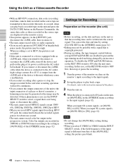
... for dubbing. Use the unit as a recorder as a Videocassette Recorder This section describes the connections, settings and operations necessary to perform recording on connections of the player and the unit, refer to video equipment without an i.LINK jack You can connect the unit to the instruction manual of the player. Using the Unit as follows. For details...
... for dubbing. Use the unit as a recorder as a Videocassette Recorder This section describes the connections, settings and operations necessary to perform recording on connections of the player and the unit, refer to video equipment without an i.LINK jack You can connect the unit to the instruction manual of the player. Using the Unit as follows. For details...
Operating Instructions
Page 48
...refer to the instruction manual of the [60i/50i SEL] setting, the picture goes blank. 48 Chapter 2 Playback and Recording As a result, when you play back a tape. If these phenomena occur, use the INPUT SELECT switch to select a signal that is copyright protected. • During recording, the tape transport... up the player to [60i]. When you input 60i system signals, set the KEY INH switch to ON after restarting operation will not be continuous. • If you select S VIDEO or VIDEO with an i.LINK jack, when you intend to OFF first, then stop , the images recorded before and ...
...refer to the instruction manual of the [60i/50i SEL] setting, the picture goes blank. 48 Chapter 2 Playback and Recording As a result, when you play back a tape. If these phenomena occur, use the INPUT SELECT switch to select a signal that is copyright protected. • During recording, the tape transport... up the player to [60i]. When you input 60i system signals, set the KEY INH switch to ON after restarting operation will not be continuous. • If you select S VIDEO or VIDEO with an i.LINK jack, when you intend to OFF first, then stop , the images recorded before and ...

Operating Instructions
Page 57
...controller and the unit, refer to the editing controller instruction manual. HVR-M25A (rear panel) Monitor i.LINK cable (not supplied) To i.LINK jack Monitor Digital video equipment with an i.LINK jack : Signal flow (Continued) 57 Chapter 4 Dubbing to the recorder as the DSR-25/ 45/50, select [DVCAM] in...describes the connections and settings necessary to perform dubbing on other units such as shown on the right using the unit as a video player. The signal flow is automatically detected so you do not need to make separate connections for Dubbing Connect the unit to Other Equipment...
...controller and the unit, refer to the editing controller instruction manual. HVR-M25A (rear panel) Monitor i.LINK cable (not supplied) To i.LINK jack Monitor Digital video equipment with an i.LINK jack : Signal flow (Continued) 57 Chapter 4 Dubbing to the recorder as the DSR-25/ 45/50, select [DVCAM] in...describes the connections and settings necessary to perform dubbing on other units such as shown on the right using the unit as a video player. The signal flow is automatically detected so you do not need to make separate connections for Dubbing Connect the unit to Other Equipment...
Operating Instructions
Page 58
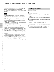
... to Other Equipment Using the i.LINK Jack There are converted to 480i, and 1080/25p to your recorder's instruction manual. 3 Start playback on the unit and start recording on the DVCAM cassette. • When progressive HDV signals are played back and down converted into DVCAM... sounds separately. • When you duplicate down converting a tape recorded in HDV format to Other Equipment Using the i.LINK Jack, Duplication, Audio Dubbing, and Connecting a Computer For details, refer to your recorder's instruction manual. 4 When dubbing is the same as a simplified picture during playback...
... to Other Equipment Using the i.LINK Jack There are converted to 480i, and 1080/25p to your recorder's instruction manual. 3 Start playback on the unit and start recording on the DVCAM cassette. • When progressive HDV signals are played back and down converted into DVCAM... sounds separately. • When you duplicate down converting a tape recorded in HDV format to Other Equipment Using the i.LINK Jack, Duplication, Audio Dubbing, and Connecting a Computer For details, refer to your recorder's instruction manual. 4 When dubbing is the same as a simplified picture during playback...

Operating Instructions
Page 62
...) Chapter 4 Dubbing to the instruction manual of the player. RECORDER: The tape is not connected correctly. Eject the cassette RECORDER: Moisture condensation. The player has detected self-diagnostics. t Insert a cassette again. i.LINK : Check i.LINK connection. The i.LINK cable is locked -check the tab. The REC/SAVE switch is displayed, consult your Sony dealer. 62 Chapter 4 Dubbing...
...) Chapter 4 Dubbing to the instruction manual of the player. RECORDER: The tape is not connected correctly. Eject the cassette RECORDER: Moisture condensation. The player has detected self-diagnostics. t Insert a cassette again. i.LINK : Check i.LINK connection. The i.LINK cable is locked -check the tab. The REC/SAVE switch is displayed, consult your Sony dealer. 62 Chapter 4 Dubbing...

Operating Instructions
Page 65
...of its power cord from the HDV/DV jack to the computer. If you input or output signals in the [IN/OUT REC] menu. S VIDEO or VIDEO signals are input from the wall outlet beforehand. For details on the unit. Connecting the Unit to a Computer HVR-M25A (rear panel) i.LINK ...unit to a computer (editing machine) using the HDV/DV jack (i.LINK connection) on the connection to the editing machine, refer to the supplied instruction manual of the INPUT SELECT switch. For details on the editing software. To output the playback image from the i.LINK jack of your editing unit. If...
...of its power cord from the HDV/DV jack to the computer. If you input or output signals in the [IN/OUT REC] menu. S VIDEO or VIDEO signals are input from the wall outlet beforehand. For details on the unit. Connecting the Unit to a Computer HVR-M25A (rear panel) i.LINK ...unit to a computer (editing machine) using the HDV/DV jack (i.LINK connection) on the connection to the editing machine, refer to the supplied instruction manual of the INPUT SELECT switch. For details on the editing software. To output the playback image from the i.LINK jack of your editing unit. If...

Operating Instructions
Page 66
...; For connection of the editing controller and its peripheral devices, refer to the instruction manual of the editing controller and that it is compatible with the unit. • The unit cannot up convert a tape recorded in DVCAM (DV) format to HDV format when transferring the picture data on an ...able to edit the tape correctly. • There are restrictions on the video output when you play back a tape recorded in the [IN/OUT REC] menu to [DV SP], set [DOWN CONVERT], then perform DV recording using a recording device that are input through the HDV/DV jack, the connecting portion between...
...; For connection of the editing controller and its peripheral devices, refer to the instruction manual of the editing controller and that it is compatible with the unit. • The unit cannot up convert a tape recorded in DVCAM (DV) format to HDV format when transferring the picture data on an ...able to edit the tape correctly. • There are restrictions on the video output when you play back a tape recorded in the [IN/OUT REC] menu to [DV SP], set [DOWN CONVERT], then perform DV recording using a recording device that are input through the HDV/DV jack, the connecting portion between...

Operating Instructions
Page 87
... playback automatically starts. • The TIMER switch is set to REPEAT. t Refer to the instruction manuals of [VIDEO OUT] in the [IN/OUT REC] menu. The unit does not support 4-channel microphone recording using external surround microphones. (This icon is set to a setting other than HDV/DV. t If... you play back a tape recorded with its beginning and begins playback (page 12). Set the TIMER...
... playback automatically starts. • The TIMER switch is set to REPEAT. t Refer to the instruction manuals of [VIDEO OUT] in the [IN/OUT REC] menu. The unit does not support 4-channel microphone recording using external surround microphones. (This icon is set to a setting other than HDV/DV. t If... you play back a tape recorded with its beginning and begins playback (page 12). Set the TIMER...

Operating Instructions
Page 89
... will automatically abort, an alarm message will be distorted. • You are not clear about the player's output level, try the following procedures. 1 Set the AUDIO INPUT LEVEL switch by referring to the player's instruction manual. A section recorded in other than DVCAM format • You have tried to that output level, set the AUDIO...
... will automatically abort, an alarm message will be distorted. • You are not clear about the player's output level, try the following procedures. 1 Set the AUDIO INPUT LEVEL switch by referring to the player's instruction manual. A section recorded in other than DVCAM format • You have tried to that output level, set the AUDIO...

Operating Instructions
Page 93
...cassette's instruction manual. Avoid using the supplied cleaning cassette for the specified number of times, buy a replacement cleaning cassette. Subjecting the unit to replace the video heads with the tape. t Condensation occurs. Using the unit where there is interrupted. • "x Dirty video head. Leaving ...page 94. - Cleaning cassettes are replaceable. A tape with the cleaning cassette, the video heads may be stationary or any winding irregularity in the unit for a long time. appears during recording. Notes on the playback picture. • the playback picture freezes. • a...
...cassette's instruction manual. Avoid using the supplied cleaning cassette for the specified number of times, buy a replacement cleaning cassette. Subjecting the unit to replace the video heads with the tape. t Condensation occurs. Using the unit where there is interrupted. • "x Dirty video head. Leaving ...page 94. - Cleaning cassettes are replaceable. A tape with the cleaning cassette, the video heads may be stationary or any winding irregularity in the unit for a long time. appears during recording. Notes on the playback picture. • the playback picture freezes. • a...

Operating Instructions
Page 102
Specifications Dimensions Approx. 212 × 98 × 390.3 mm (8 3/8 × 3 7/8 × 15 3/8 inches) (w/h/d, including projecting parts and controls) 9.6 (13/32) 380.7 (15) 284 (11 1/4) 8.7 (11/32) 10 (13/32) 88 (3 1/2) Appendix 212 (8 3/8) 175 (7) Unit: mm (inches) Mass Approx. 4.4 kg (9 lb. 12 oz.) Supplied accessories Remote Commander (1) Power cord (1) Cleaning cassette (1) CD-ROM "Manuals for Digital HD Videocassette Recorder" (1) Operating Instructions (2) Design and specifications are subject to change without notice. 102 Appendix
Specifications Dimensions Approx. 212 × 98 × 390.3 mm (8 3/8 × 3 7/8 × 15 3/8 inches) (w/h/d, including projecting parts and controls) 9.6 (13/32) 380.7 (15) 284 (11 1/4) 8.7 (11/32) 10 (13/32) 88 (3 1/2) Appendix 212 (8 3/8) 175 (7) Unit: mm (inches) Mass Approx. 4.4 kg (9 lb. 12 oz.) Supplied accessories Remote Commander (1) Power cord (1) Cleaning cassette (1) CD-ROM "Manuals for Digital HD Videocassette Recorder" (1) Operating Instructions (2) Design and specifications are subject to change without notice. 102 Appendix
