
Operating Instructions
Page 1
HVR-M15AU/M15AN/M15AE/ M15AP © 2008 Sony Corporation 3-878-917-11 (1) Digital HD Videocassette Recorder Operating Instructions Before operating the unit, please read this manual thoroughly, and retain it for future reference.
HVR-M15AU/M15AN/M15AE/ M15AP © 2008 Sony Corporation 3-878-917-11 (1) Digital HD Videocassette Recorder Operating Instructions Before operating the unit, please read this manual thoroughly, and retain it for future reference.

Operating Instructions
Page 5
...VIDEO OUT jack. • Digital hours meter: A digital hours meter counts four types of Japan, Ltd. "™" and "®" are not mentioned in every case in this manual. Screen Language Setting You can select the language to be output when the tape is a trademark of Sony...their respective companies. operating time, drum rotation time, tape running time, and tape threading/unthreading. is recorded in HDV format.) , , and are trademarks of Sony Corporation. Chapter 1 Overview Multiple input/output interfaces The following jacks are provided with the unit and ...
...VIDEO OUT jack. • Digital hours meter: A digital hours meter counts four types of Japan, Ltd. "™" and "®" are not mentioned in every case in this manual. Screen Language Setting You can select the language to be output when the tape is a trademark of Sony...their respective companies. operating time, drum rotation time, tape running time, and tape threading/unthreading. is recorded in HDV format.) , , and are trademarks of Sony Corporation. Chapter 1 Overview Multiple input/output interfaces The following jacks are provided with the unit and ...

Operating Instructions
Page 14
... or recording condition is supplied. Signals from the VIDEO IN jacks or S VIDEO IN jacks, are output to the jitter. Video signals in EE mode, the subcarrier of the screen. Pictures may cause a malfunction. • Even though the HDV/DV jack of the jack. For details, refer to the instruction manual of ...the TV monitor display due to the VIDEO OUT jacks. Notes • When you use a DSRM-20 (no power is bad) played by a VCR that does not ...
... or recording condition is supplied. Signals from the VIDEO IN jacks or S VIDEO IN jacks, are output to the jitter. Video signals in EE mode, the subcarrier of the screen. Pictures may cause a malfunction. • Even though the HDV/DV jack of the jack. For details, refer to the instruction manual of ...the TV monitor display due to the VIDEO OUT jacks. Notes • When you use a DSRM-20 (no power is bad) played by a VCR that does not ...

Operating Instructions
Page 18
... on the built-in the "OTHERS" menu on page 23. You cannot specify the items of the INPUT SELECT switch. ([HDV/DV IN], [S VIDEO IN] or [VIDEO IN]) k (Index) indicator Displays when an index has been marked. 18 Chapter 1 Overview b 60i/24p/30p/50i/25p indicator c Repeat indicator ... English. When an HVR-MRC1 is connected, [CF] is displayed after the tape runs for normal recording or playback, such as time code or remaining tape time, on page 65. The remaining tape time is displayed. Menu screen Press the MENU button to the beginning, this operation manual, the menu screen...
... on the built-in the "OTHERS" menu on page 23. You cannot specify the items of the INPUT SELECT switch. ([HDV/DV IN], [S VIDEO IN] or [VIDEO IN]) k (Index) indicator Displays when an index has been marked. 18 Chapter 1 Overview b 60i/24p/30p/50i/25p indicator c Repeat indicator ... English. When an HVR-MRC1 is connected, [CF] is displayed after the tape runs for normal recording or playback, such as time code or remaining tape time, on page 65. The remaining tape time is displayed. Menu screen Press the MENU button to the beginning, this operation manual, the menu screen...
Operating Instructions
Page 30
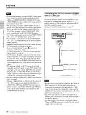
HVR-M15A (rear panel) i.LINK cable (not supplied) To i.LINK jack ( HDV/DV jack) Monitor with i.LINK jack : Signal flow Notes • Be sure that you ... you connect the monitor using a component video cable, set [COMPONENT] of [VIDEO OUT] in the [IN/OUT REC] menu according to the requirements of your monitor's instruction manual. • When an i.LINK connection is set the monitor so that it recognizes the unit. For more information, see "Recording Format and Input/ Output Signals" on...
HVR-M15A (rear panel) i.LINK cable (not supplied) To i.LINK jack ( HDV/DV jack) Monitor with i.LINK jack : Signal flow Notes • Be sure that you ... you connect the monitor using a component video cable, set [COMPONENT] of [VIDEO OUT] in the [IN/OUT REC] menu according to the requirements of your monitor's instruction manual. • When an i.LINK connection is set the monitor so that it recognizes the unit. For more information, see "Recording Format and Input/ Output Signals" on...

Operating Instructions
Page 31
...monitor, a humming noise may be generated or the image may be output from the HDV/DV jack. For details, refer to your monitor's instruction manual. • With HDV signals, interlace to progressive or progressive to interlace conversions cannot be made and be output via the HDV/DV jack. •... on a DVcompatible monitor, set the monitor's input switch according to the VIDEO OUT jack, S VIDEO OUT jack, and COMPONENT OUT jacks. If these phenomena occur, use the INPUT SELECT switch to OFF. To play back an image recorded in the HDV mode on text data, see page 6. Settings for Playback...
...monitor, a humming noise may be generated or the image may be output from the HDV/DV jack. For details, refer to your monitor's instruction manual. • With HDV signals, interlace to progressive or progressive to interlace conversions cannot be made and be output via the HDV/DV jack. •... on a DVcompatible monitor, set the monitor's input switch according to the VIDEO OUT jack, S VIDEO OUT jack, and COMPONENT OUT jacks. If these phenomena occur, use the INPUT SELECT switch to OFF. To play back an image recorded in the HDV mode on text data, see page 6. Settings for Playback...

Operating Instructions
Page 36
... for dubbing. Player Monitor HVR-M15A (rear panel) Monitor Chapter 2 Playback and Recording To audio output To video output To S-video output Audio cable (not supplied) Video cable (not supplied) S-video cable (not supplied) Connect either an S-video cable or a video cable. 36 Chapter 2 Playback and Recording : Signal flow...when you are using the unit for Recording To video equipment without an i.LINK jack You can connect the unit to perform recording on connections of the player and the unit, refer to the instruction manual of the player. Note For details on the unit. ...
... for dubbing. Player Monitor HVR-M15A (rear panel) Monitor Chapter 2 Playback and Recording To audio output To video output To S-video output Audio cable (not supplied) Video cable (not supplied) S-video cable (not supplied) Connect either an S-video cable or a video cable. 36 Chapter 2 Playback and Recording : Signal flow...when you are using the unit for Recording To video equipment without an i.LINK jack You can connect the unit to perform recording on connections of the player and the unit, refer to the instruction manual of the player. Note For details on the unit. ...

Operating Instructions
Page 38
... instruction manual of HDV. • When you input 60i system signals, set [60i/50i SEL] to [60i]. When you record HDV signals input from being input, or disconnect the cables. • The unit cannot record MPEG2 signals except 1080/ 60i, 1080/24p, 1080/30p, 1080/50i, 1080/25p of the player. 3...8226; If no picture appears via the HDV/DV jack, disconnect the i.LINK cable, then reconnect it. • The unit cannot record video or audio separately. • If you select S VIDEO or VIDEO with an i.LINK jack, when you input 50i system signals, set [60i/50i SEL] to [50i] (page 58). Notes &#...
... instruction manual of HDV. • When you input 60i system signals, set [60i/50i SEL] to [60i]. When you record HDV signals input from being input, or disconnect the cables. • The unit cannot record MPEG2 signals except 1080/ 60i, 1080/24p, 1080/30p, 1080/50i, 1080/25p of the player. 3...8226; If no picture appears via the HDV/DV jack, disconnect the i.LINK cable, then reconnect it. • The unit cannot record video or audio separately. • If you select S VIDEO or VIDEO with an i.LINK jack, when you input 50i system signals, set [60i/50i SEL] to [50i] (page 58). Notes &#...

Operating Instructions
Page 41
...format in which you do not need to make separate connections for Dubbing HVR-M15A (rear panel) Monitor To digital video equipment with an i.LINK jack : Signal flow There are some limitations to down converting a tape recorded in HDV format to DVCAM format. For details, refer to "Major Differences..., select [DVCAM] in [HDV t DV CONV] of the editing controller and the unit, refer to the editing controller instruction manual. Also, by connecting the unit to the recorder as a video player. Make [HDV/DV SEL] (page 50) and [i.LINK SET] (page 51) settings in HDV format using the unit as...
...format in which you do not need to make separate connections for Dubbing HVR-M15A (rear panel) Monitor To digital video equipment with an i.LINK jack : Signal flow There are some limitations to down converting a tape recorded in HDV format to DVCAM format. For details, refer to "Major Differences..., select [DVCAM] in [HDV t DV CONV] of the editing controller and the unit, refer to the editing controller instruction manual. Also, by connecting the unit to the recorder as a video player. Make [HDV/DV SEL] (page 50) and [i.LINK SET] (page 51) settings in HDV format using the unit as...

Operating Instructions
Page 44
Chapter 3 Dubbing/Editing Dubbing to "Playback Procedures" on page 31. Refer to Other Equipment Dubbing Procedures 1 Prepare the unit. Refer to your recorder's instruction manual. 3 Start playback on the unit and start recording on the recorder. For details, refer to your recorder's instruction manual. 4 When dubbing is finished, stop playback of the unit. 44 Chapter 3 Dubbing/Editing For details, refer to "Settings for Playback" on the recorder, and then stop recording on page 31. 2 Prepare the recorder. If the recorder has an input selector switch, select an input.
Chapter 3 Dubbing/Editing Dubbing to "Playback Procedures" on page 31. Refer to Other Equipment Dubbing Procedures 1 Prepare the unit. Refer to your recorder's instruction manual. 3 Start playback on the unit and start recording on the recorder. For details, refer to your recorder's instruction manual. 4 When dubbing is finished, stop playback of the unit. 44 Chapter 3 Dubbing/Editing For details, refer to "Settings for Playback" on the recorder, and then stop recording on page 31. 2 Prepare the recorder. If the recorder has an input selector switch, select an input.

Operating Instructions
Page 45
... connecting the i.LINK cable, set up an editing system by connecting the unit to the instruction manual of your editing software. Chapter 3 Dubbing/Editing Editing (Connecting a Computer) You can use depend on the... editing software. Connecting the Unit to a Computer HVR-M15A (rear panel) i.LINK cable (not supplied) Notes • Be sure to connect the i.LINK... out the plug of the INPUT SELECT switch. If you intend to HDV/DV. S VIDEO or VIDEO signals are input from the HDV/DV jack, according to the setting of its power cord...
... connecting the i.LINK cable, set up an editing system by connecting the unit to the instruction manual of your editing software. Chapter 3 Dubbing/Editing Editing (Connecting a Computer) You can use depend on the... editing software. Connecting the Unit to a Computer HVR-M15A (rear panel) i.LINK cable (not supplied) Notes • Be sure to connect the i.LINK... out the plug of the INPUT SELECT switch. If you intend to HDV/DV. S VIDEO or VIDEO signals are input from the HDV/DV jack, according to the setting of its power cord...

Operating Instructions
Page 46
...in "Playing at various speeds. Some software may not edit DVCAM/DV signals that are restrictions on the video output when you play back a tape recorded in an error. • When you record HDV signals that is compatible with some conventional DVCAM/DV editing software may not work with the unit. .... We recommend you use a tape that accepts DV format. 46 Chapter 3 Dubbing/Editing For details on editing methods, refer to the instruction manual of your editing software has the capability to output the time code as well as a still picture for tape duplication, then use depend on ...
...in "Playing at various speeds. Some software may not edit DVCAM/DV signals that are restrictions on the video output when you play back a tape recorded in an error. • When you record HDV signals that is compatible with some conventional DVCAM/DV editing software may not work with the unit. .... We recommend you use a tape that accepts DV format. 46 Chapter 3 Dubbing/Editing For details on editing methods, refer to the instruction manual of your editing software has the capability to output the time code as well as a still picture for tape duplication, then use depend on ...

Operating Instructions
Page 54
... signal is selected, regardless of the input amplifier. AUDIO LOCK (pages 39, 71) BUNLOCK MODE :Records the sampling clocks of the audio and video for analog audio input (CH-1 and 2) while recording. -6 dB : Decreases 6 dB from the original audio input level. AUDIO AGC (page 39) ...audio editing process. BFS48K : Switches the audio mode to adjust the [AUDIO REC LV] automatically or not. OFF : Adjusts the audio recording level manually. (Set the audio recording level with [AUDIO REC LV] (page 54).) Note Even when this menu. MIX : Outputs the synthesized audio of channels 1 and...
... signal is selected, regardless of the input amplifier. AUDIO LOCK (pages 39, 71) BUNLOCK MODE :Records the sampling clocks of the audio and video for analog audio input (CH-1 and 2) while recording. -6 dB : Decreases 6 dB from the original audio input level. AUDIO AGC (page 39) ...audio editing process. BFS48K : Switches the audio mode to adjust the [AUDIO REC LV] automatically or not. OFF : Adjusts the audio recording level manually. (Set the audio recording level with [AUDIO REC LV] (page 54).) Note Even when this menu. MIX : Outputs the synthesized audio of channels 1 and...

Operating Instructions
Page 62
...ON]. t Set [AUTO REPEAT] to [OFF]. • When [COMMANDER] in the [OTHERS] menu is not recorded. • The i.LINK signal output from the digital non-linear editing controller does not include a time code. ... SELECT switch is released automatically. • To protect the tape and the video heads, the unit goes into the stop mode after the playback pause mode continues for more ...mode is not displayed. Set [AUDIO MIX] in forward or reverse. t Set [COMMANDER] to the instruction manuals of normal speed in the [AUDIO SET] menu according to [OFF]. t Refer to [CONTROL S]. Although ...
...ON]. t Set [AUTO REPEAT] to [OFF]. • When [COMMANDER] in the [OTHERS] menu is not recorded. • The i.LINK signal output from the digital non-linear editing controller does not include a time code. ... SELECT switch is released automatically. • To protect the tape and the video heads, the unit goes into the stop mode after the playback pause mode continues for more ...mode is not displayed. Set [AUDIO MIX] in forward or reverse. t Set [COMMANDER] to the instruction manuals of normal speed in the [AUDIO SET] menu according to [OFF]. t Refer to [CONTROL S]. Although ...

Operating Instructions
Page 63
.... The recorded level is connected when you edit the dubbing, the monitor does not display any image. If an i.LINK cable is too low. EE sound is distorted. Cause/Remedy t Reconnect the i.LINK cable (not supplied). • INPUT SELECT switch is set to the player's instruction manual. Confirm ...Connect the unit to [PB]. HDV/DV You do not know how to the signal input. • With an analog connection, the current setting of [VIDEO OUT] in the [OTHERS] menu is not appropriate. t Set the switch according to adjust the input level. Chapter 5 Maintenance (Continued) 63 Chapter 5 ...
.... The recorded level is connected when you edit the dubbing, the monitor does not display any image. If an i.LINK cable is too low. EE sound is distorted. Cause/Remedy t Reconnect the i.LINK cable (not supplied). • INPUT SELECT switch is set to the player's instruction manual. Confirm ...Connect the unit to [PB]. HDV/DV You do not know how to the signal input. • With an analog connection, the current setting of [VIDEO OUT] in the [OTHERS] menu is not appropriate. t Set the switch according to adjust the input level. Chapter 5 Maintenance (Continued) 63 Chapter 5 ...

Operating Instructions
Page 64
Chapter 5 Maintenance 64 Chapter 5 Maintenance Cause/Remedy • The INPUT SELECT switch is not compatible with the unit. The functions on the unit do not operate. t Set it to HDV/DV (page 6). • The editing controller or the editing software is set to the instruction manuals of a digital non-linear editing system. t Refer to a setting other than HDV/DV. Troubleshooting Symptom The unit does not function as part of the controller or the software and consult their manufacturers.
Chapter 5 Maintenance 64 Chapter 5 Maintenance Cause/Remedy • The INPUT SELECT switch is not compatible with the unit. The functions on the unit do not operate. t Set it to HDV/DV (page 6). • The editing controller or the editing software is set to the instruction manuals of a digital non-linear editing system. t Refer to a setting other than HDV/DV. Troubleshooting Symptom The unit does not function as part of the controller or the software and consult their manufacturers.

Operating Instructions
Page 68
... Please consult your cleaning cassette's instruction manual. Using the unit for a long time. Normal image Playback Playback image image pauses disappears With a DV/DVCAM A moldy tape A dirty tape A spliced tape Playback image disappears To use , the video heads may occur anyway. Avoid using ...problem with the cleaning cassette, the video heads may become worn out. Notes on Use When the symptoms caused by playing the cleaning cassette for ten seconds. *If the playback image continues to your Sony dealer. appears during recording. For details, refer to be ...
... Please consult your cleaning cassette's instruction manual. Using the unit for a long time. Normal image Playback Playback image image pauses disappears With a DV/DVCAM A moldy tape A dirty tape A spliced tape Playback image disappears To use , the video heads may occur anyway. Avoid using ...problem with the cleaning cassette, the video heads may become worn out. Notes on Use When the symptoms caused by playing the cleaning cassette for ten seconds. *If the playback image continues to your Sony dealer. appears during recording. For details, refer to be ...

Operating Instructions
Page 77
Design and specifications are subject to +140 °F) * See the label on the AC Adaptor for Digital HD Videocassette Recorder" (1) Operating Instructions (2) AC Adaptor AC-L100 Power requirements AC 100 V - 240 V, 50 Hz/60 Hz Current consumption 0.35 A - 0.18 A Power consumption 18 W Output voltage DC ...;F to change without notice. 77 Appendix Appendix Mass Approx. 2.3 kg (5 lb. 1 oz.) Supplied accessories Remote Commander (1) AC Adaptor (1) Power cord (1) Rack (1) Cleaning cassette (1) CD-ROM "Manuals for other specifications.
Design and specifications are subject to +140 °F) * See the label on the AC Adaptor for Digital HD Videocassette Recorder" (1) Operating Instructions (2) AC Adaptor AC-L100 Power requirements AC 100 V - 240 V, 50 Hz/60 Hz Current consumption 0.35 A - 0.18 A Power consumption 18 W Output voltage DC ...;F to change without notice. 77 Appendix Appendix Mass Approx. 2.3 kg (5 lb. 1 oz.) Supplied accessories Remote Commander (1) AC Adaptor (1) Power cord (1) Rack (1) Cleaning cassette (1) CD-ROM "Manuals for other specifications.
