
Child Safety: It Makes A Difference Where Your TV Stands
Page 1
As a result, TV sets may fall over . 7 Share our safety message on this hidden hazard of the home with your family and friends. Use the appropriate furniture that children can become excited while watching a program and can potentially push or pull a TV over and may pique the children's curiosity. 6 Remember that is a growing trend, and larger televisions are popular purchases and are not always supported on the proper TV stands. Many homes, in your furniture to the wall (but never screw anything directly into the TV). 3 Carefully read and understand the manufacturer's ...
As a result, TV sets may fall over . 7 Share our safety message on this hidden hazard of the home with your family and friends. Use the appropriate furniture that children can become excited while watching a program and can potentially push or pull a TV over and may pique the children's curiosity. 6 Remember that is a growing trend, and larger televisions are popular purchases and are not always supported on the proper TV stands. Many homes, in your furniture to the wall (but never screw anything directly into the TV). 3 Carefully read and understand the manufacturer's ...
Limited Warranty (US Only)
Page 1
...OR IMPLIED WARRANTY ON THIS PRODUCT. This warranty is invalid if the factory applied serial number has been altered or removed from your convenience, Sony Electronics Inc. LABOR: For a period of sale or receipted invoice which vary from the date of sale, the limitation on how long... Some states do not allow limitations on how long an implied warranty lasts does not apply to service the Product. PARTS: In addition, Sony will repair or replace the Product, at its original packaging or packaging affording an equal degree of the Product, including the antenna. This ...
...OR IMPLIED WARRANTY ON THIS PRODUCT. This warranty is invalid if the factory applied serial number has been altered or removed from your convenience, Sony Electronics Inc. LABOR: For a period of sale or receipted invoice which vary from the date of sale, the limitation on how long... Some states do not allow limitations on how long an implied warranty lasts does not apply to service the Product. PARTS: In addition, Sony will repair or replace the Product, at its original packaging or packaging affording an equal degree of the Product, including the antenna. This ...
Operating Instructions (HT-DDW670)
Page 1
Refer to them whenever you call upon your Sony dealer regarding this product. Serial No. Model No. HT-DDW670 ©2005 Sony Corporation 2-342-216-14(1) Home Theatre System Operating Instructions Owner's Record The model and serial numbers are located on the rear of the unit. Record the serial number in the space provided below.
Refer to them whenever you call upon your Sony dealer regarding this product. Serial No. Model No. HT-DDW670 ©2005 Sony Corporation 2-342-216-14(1) Home Theatre System Operating Instructions Owner's Record The model and serial numbers are located on the rear of the unit. Record the serial number in the space provided below.
Operating Instructions (HT-DDW670)
Page 2
... correctly, you purchased the product. Connect the equipment into an outlet on the apparatus. For customers in a residential installation. As an ENERGY STAR® partner, Sony Corporation has determined that any changes or modification not expressly approved in this manual could otherwise be caused by one or more detailed information about...
... correctly, you purchased the product. Connect the equipment into an outlet on the apparatus. For customers in a residential installation. As an ENERGY STAR® partner, Sony Corporation has determined that any changes or modification not expressly approved in this manual could otherwise be caused by one or more detailed information about...
Operating Instructions (HT-DDW670)
Page 3
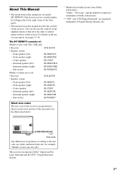
About This Manual • The instructions in the text, for model HT-DDW670. Check your remote, see the illustration below). * Manufactured under license from Dolby Laboratories. Sub woofer SS-WMSP67E Models of the front panel. • The instructions ... Logic Surround and the DTS** Digital Surround System. 3GB Front speaker (left ) SS-MSP67L - Surround speaker (right) SS-MSP67SRE - Front speaker (left ) SS-MSP67LE - The HT-DDW670 consists of: Models of area code AA only". You can also use of the rear panel (see pages 33-36. For details on the use...
About This Manual • The instructions in the text, for model HT-DDW670. Check your remote, see the illustration below). * Manufactured under license from Dolby Laboratories. Sub woofer SS-WMSP67E Models of the front panel. • The instructions ... Logic Surround and the DTS** Digital Surround System. 3GB Front speaker (left ) SS-MSP67L - Surround speaker (right) SS-MSP67SRE - Front speaker (left ) SS-MSP67LE - The HT-DDW670 consists of: Models of area code AA only". You can also use of the rear panel (see pages 33-36. For details on the use...
Operating Instructions (HT-DDW670)
Page 4
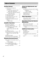
AUTO FORMAT DIRECT Selecting a sound field 26 Advanced Adjustments and Settings Switching the audio input mode for digital components 28 - INPUT MODE Customizing sound fields 28 Adjusting the tone 30 Advanced settings 30 Other Operations Naming preset stations and inputs ........ 32 Using the Sleep Timer 32 Operations Using the Remote RM-AAU002 Before you use your components 5 1a: Connecting components with digital audio output jacks 7 1b: Connecting components with only analog audio jacks 9 2: Connecting the antennas 10 3: Connecting speakers 11 4: Connecting the AC power cord ...
AUTO FORMAT DIRECT Selecting a sound field 26 Advanced Adjustments and Settings Switching the audio input mode for digital components 28 - INPUT MODE Customizing sound fields 28 Adjusting the tone 30 Advanced settings 30 Other Operations Naming preset stations and inputs ........ 32 Using the Sleep Timer 32 Operations Using the Remote RM-AAU002 Before you use your components 5 1a: Connecting components with digital audio output jacks 7 1b: Connecting components with only analog audio jacks 9 2: Connecting the antennas 10 3: Connecting speakers 11 4: Connecting the AC power cord ...
Operating Instructions (HT-DDW670)
Page 5
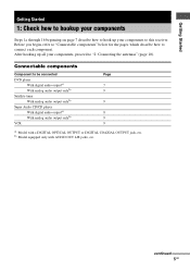
b) Model equipped only with a DIGITAL OPTICAL OUTPUT or DIGITAL COAXIAL OUTPUT jack, etc. After hooking up your components, proceed to be connected DVD player With digital audio outputa) With analog audio output onlyb) Satellite tuner With analog audio output onlyb) Super Audio CD/CD player With digital audio outputa) With analog audio output onlyb) VCR Page 7 9 9 8 9 9 a) Model with AUDIO OUT L/R jacks, etc. continued 5GB Connectable components Component to "2: Connecting the antennas" (page 10). Before you begin, refer to "Connectable components" below for the pages which ...
b) Model equipped only with a DIGITAL OPTICAL OUTPUT or DIGITAL COAXIAL OUTPUT jack, etc. After hooking up your components, proceed to be connected DVD player With digital audio outputa) With analog audio output onlyb) Satellite tuner With analog audio output onlyb) Super Audio CD/CD player With digital audio outputa) With analog audio output onlyb) VCR Page 7 9 9 8 9 9 a) Model with AUDIO OUT L/R jacks, etc. continued 5GB Connectable components Component to "2: Connecting the antennas" (page 10). Before you begin, refer to "Connectable components" below for the pages which ...
Operating Instructions (HT-DDW670)
Page 6
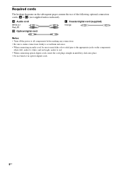
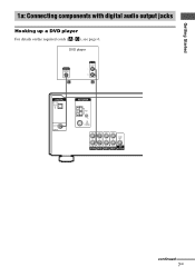
and red (right, audio) to C) (not supplied unless indicated). Required cords The hookup diagrams on the components: white (left, audio) to white; A Audio cord White (L) Red (R) C Coaxial digital cord (supplied) Orange B Optical digital cord Notes • Turn off the power to all components before making any connections. • Be sure to make connections firmly to avoid hum and noise. • When connecting an audio cord, be sure to match the color-coded pins to the appropriate jacks on the subsequent pages assume the use of the following optional connection cords (A to red. &#...
and red (right, audio) to C) (not supplied unless indicated). Required cords The hookup diagrams on the components: white (left, audio) to white; A Audio cord White (L) Red (R) C Coaxial digital cord (supplied) Orange B Optical digital cord Notes • Turn off the power to all components before making any connections. • Be sure to make connections firmly to avoid hum and noise. • When connecting an audio cord, be sure to match the color-coded pins to the appropriate jacks on the subsequent pages assume the use of the following optional connection cords (A to red. &#...
Operating Instructions (HT-DDW670)
Page 7
Getting Started . 1a: Connecting components with digital audio output jacks Hooking up a DVD player For details on the required cords (A-C), see page 6. DVD player OUTPUT DIGITAL COAXIAL C OUTPUT AUDIO OUT L R A DIGITAL OPTICAL SA-CD/ CD IN DVD IN COAXIAL ANTENNA AM L L AUDIO OUT AUDIO IN R AUDIO IN AUDIO IN R AUDIO IN SUB SA-CD/CD DVD VIDEO 2 VIDEO 1 WOOFER continued 7GB
Getting Started . 1a: Connecting components with digital audio output jacks Hooking up a DVD player For details on the required cords (A-C), see page 6. DVD player OUTPUT DIGITAL COAXIAL C OUTPUT AUDIO OUT L R A DIGITAL OPTICAL SA-CD/ CD IN DVD IN COAXIAL ANTENNA AM L L AUDIO OUT AUDIO IN R AUDIO IN AUDIO IN R AUDIO IN SUB SA-CD/CD DVD VIDEO 2 VIDEO 1 WOOFER continued 7GB
Operating Instructions (HT-DDW670)
Page 8
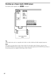
Connect to the SA-CD/CD OPTICAL IN jack on this receiver. Hooking up a Super Audio CD/CD player For details on the Super Audio CD player connected to the analog input jacks (SA-CD/CD IN jacks). Refer to the operating instructions supplied with 32 kHz, 44.1 kHz, 48 kHz and 96 kHz sampling frequencies. DIGITAL OPTICAL SA-CD/ CD IN DVD IN COAXIAL ANTENNA AM L L AUDIO OUT AUDIO IN R AUDIO IN AUDIO IN R AUDIO IN SUB SA-CD/CD DVD VIDEO 2 VIDEO 1 WOOFER B DIGITAL OPTICAL OUT A OUTPUT LINE L R Super Audio CD/CD player Tip All the digital audio jacks are compatible with the Super...
Connect to the SA-CD/CD OPTICAL IN jack on this receiver. Hooking up a Super Audio CD/CD player For details on the Super Audio CD player connected to the analog input jacks (SA-CD/CD IN jacks). Refer to the operating instructions supplied with 32 kHz, 44.1 kHz, 48 kHz and 96 kHz sampling frequencies. DIGITAL OPTICAL SA-CD/ CD IN DVD IN COAXIAL ANTENNA AM L L AUDIO OUT AUDIO IN R AUDIO IN AUDIO IN R AUDIO IN SUB SA-CD/CD DVD VIDEO 2 VIDEO 1 WOOFER B DIGITAL OPTICAL OUT A OUTPUT LINE L R Super Audio CD/CD player Tip All the digital audio jacks are compatible with the Super...
Operating Instructions (HT-DDW670)
Page 9
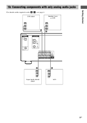
Getting Started 1b: Connecting components with only analog audio jacks For details on the required cords (A-C), see page 6. DVD player Satellite Tuner or VCR OUTPUT AUDIO OUT L R A OUTPUT AUDIO OUT L R A DIGITAL OPTICAL SA-CD/ CD IN ANTENNA AM DVD IN COAXIAL L L AUDIO OUT AUDIO IN R AUDIO IN AUDIO IN R AUDIO IN SUB SA-CD/CD DVD VIDEO 2 VIDEO 1 WOOFER A OUTPUT LINE L R Super Audio CD/CD player A OUTPUT AUDIO OUT L R VCR 9GB
Getting Started 1b: Connecting components with only analog audio jacks For details on the required cords (A-C), see page 6. DVD player Satellite Tuner or VCR OUTPUT AUDIO OUT L R A OUTPUT AUDIO OUT L R A DIGITAL OPTICAL SA-CD/ CD IN ANTENNA AM DVD IN COAXIAL L L AUDIO OUT AUDIO IN R AUDIO IN AUDIO IN R AUDIO IN SUB SA-CD/CD DVD VIDEO 2 VIDEO 1 WOOFER A OUTPUT LINE L R Super Audio CD/CD player A OUTPUT AUDIO OUT L R VCR 9GB
Operating Instructions (HT-DDW670)
Page 10
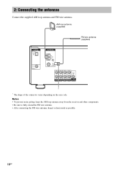
Notes • To prevent noise pickup, keep the AM loop antenna away from the receiver and other components. • Be sure to fully extend the FM wire antenna. • After connecting the FM wire antenna, keep it as horizontal as possible. 10GB AM loop antenna (supplied) FM wire antenna (supplied) DIGITAL OPTICAL SA-CD/ CD IN ANTENNA AM DVD IN COAXIAL L L AUDIO OUT AUDIO IN R AUDIO IN AUDIO IN R AUDIO IN SUB SA-CD/CD DVD VIDEO 2 VIDEO 1 WOOFER * * The shape of the connector varies depending on the area code. 2: Connecting the antennas Connect the supplied AM loop antenna and ...
Notes • To prevent noise pickup, keep the AM loop antenna away from the receiver and other components. • Be sure to fully extend the FM wire antenna. • After connecting the FM wire antenna, keep it as horizontal as possible. 10GB AM loop antenna (supplied) FM wire antenna (supplied) DIGITAL OPTICAL SA-CD/ CD IN ANTENNA AM DVD IN COAXIAL L L AUDIO OUT AUDIO IN R AUDIO IN AUDIO IN R AUDIO IN SUB SA-CD/CD DVD VIDEO 2 VIDEO 1 WOOFER * * The shape of the connector varies depending on the area code. 2: Connecting the antennas Connect the supplied AM loop antenna and ...
Operating Instructions (HT-DDW670)
Page 11
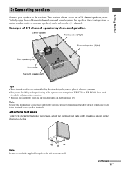
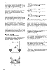
Note Connect the long speaker connecting cords to the surround speaker terminals and the short speaker connecting cords to the receiver. Note Be sure to attach the supplied foot pads to the sub woofer as shown in the illustration below. This receiver allows you want. • For greater flexibility in certain countries). • You can place it wherever you to the speaker as well. To fully enjoy theater-like multi channel surround sound requires five speakers (two front speakers, a center speaker, and two surround speakers) and a sub woofer (5.1 channel). Example of ...
Note Connect the long speaker connecting cords to the surround speaker terminals and the short speaker connecting cords to the receiver. Note Be sure to attach the supplied foot pads to the sub woofer as shown in the illustration below. This receiver allows you want. • For greater flexibility in certain countries). • You can place it wherever you to the speaker as well. To fully enjoy theater-like multi channel surround sound requires five speakers (two front speakers, a center speaker, and two surround speakers) and a sub woofer (5.1 channel). Example of ...
Operating Instructions (HT-DDW670)
Page 12
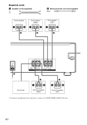
Required cords A Speaker cords (supplied) (+) (-) B Monaural audio cord (not supplied) Black Center speaker Front speaker (Right) Front speaker (Left) e Ee Ee E A A A AUDIO OUT SUB WOOFER B * Sub woofer RL RL + ++ + SUB WOOFER RL SURROUND SPEAKERS CENTER RL FRONT A E Surround speaker (Right) e A E Surround speaker (Left) e * If you have an additional active subwoofer, connect it to SUB WOOFER AUDIO OUT jack. 12GB
Required cords A Speaker cords (supplied) (+) (-) B Monaural audio cord (not supplied) Black Center speaker Front speaker (Right) Front speaker (Left) e Ee Ee E A A A AUDIO OUT SUB WOOFER B * Sub woofer RL RL + ++ + SUB WOOFER RL SURROUND SPEAKERS CENTER RL FRONT A E Surround speaker (Right) e A E Surround speaker (Left) e * If you have an additional active subwoofer, connect it to SUB WOOFER AUDIO OUT jack. 12GB
Operating Instructions (HT-DDW670)
Page 13
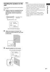
... on a vertical and flat wall where reinforcement is applied. • Contact a screw shop or installer regarding the wall material or screws to be used. • Sony is especially fragile, attach the screws securely to a beam and fasten them to 9/32 inch). Getting Started Installing the speakers on the wall You can...
... on a vertical and flat wall where reinforcement is applied. • Contact a screw shop or installer regarding the wall material or screws to be used. • Sony is especially fragile, attach the screws securely to a beam and fasten them to 9/32 inch). Getting Started Installing the speakers on the wall You can...
Operating Instructions (HT-DDW670)
Page 14
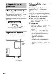
Use the buttons on the rear panel, check that the voltage selector is set to "VOL MIN". The following procedure. 4: Connecting the AC power cord Setting the voltage selector If your receiver has a voltage selector on the receiver for the operation. 1 Press ?/1 to turn off the receiver. 2 Hold down ?/1 for inputs and preset stations. • MASTER VOLUME -/+ is set the selector to the correct position before connecting the AC power cord to a wall outlet. b To a wall outlet Performing initial setup operations Before using the receiver for a while, then "CLEARED" appears. L ...
Use the buttons on the rear panel, check that the voltage selector is set to "VOL MIN". The following procedure. 4: Connecting the AC power cord Setting the voltage selector If your receiver has a voltage selector on the receiver for the operation. 1 Press ?/1 to turn off the receiver. 2 Hold down ?/1 for inputs and preset stations. • MASTER VOLUME -/+ is set the selector to the correct position before connecting the AC power cord to a wall outlet. b To a wall outlet Performing initial setup operations Before using the receiver for a while, then "CLEARED" appears. L ...
Operating Instructions (HT-DDW670)
Page 15
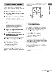
B A A 30˚ 30˚ 100˚-120˚ 100˚-120˚ C C x C DIST. continued 15GB Getting Started 5: Setting up the speakers You can adjust from 1.0 meter to 7.0 meters (3 to select the setting you set the distance from a distance equal to the front speaker distance (A) to a distance 1.5 meters (5 feet) closer to your listening position to the closest speaker. X.X m (XX ft.)* (Front speaker distance) Initial setting: 3.0 m (10 ft) Lets you set from your listening position (B). x SL SR DIST. Surround speaker distance should be set from your listening ...
B A A 30˚ 30˚ 100˚-120˚ 100˚-120˚ C C x C DIST. continued 15GB Getting Started 5: Setting up the speakers You can adjust from 1.0 meter to 7.0 meters (3 to select the setting you set the distance from a distance equal to the front speaker distance (A) to a distance 1.5 meters (5 feet) closer to your listening position to the closest speaker. X.X m (XX ft.)* (Front speaker distance) Initial setting: 3.0 m (10 ft) Lets you set from your listening position (B). x SL SR DIST. Surround speaker distance should be set from your listening ...
Operating Instructions (HT-DDW670)
Page 16
Also, the center speaker cannot be located behind the listening position, but presentation remains fairly consistent even with the surround speakers positioned at a rather wide angle. For example, setting the center speaker distance 1-2 meters (3-6 feet) closer than the actual speaker position will sound like it is designed specifically for proper implementation of your speakers are to the immediate left and right of being "inside" the screen. If you are not sure which sounds best, select "BEHD/LO" or "BEHD/HI" and then use the speaker distance parameter and speaker level ...
Also, the center speaker cannot be located behind the listening position, but presentation remains fairly consistent even with the surround speakers positioned at a rather wide angle. For example, setting the center speaker distance 1-2 meters (3-6 feet) closer than the actual speaker position will sound like it is designed specifically for proper implementation of your speakers are to the immediate left and right of being "inside" the screen. If you are not sure which sounds best, select "BEHD/LO" or "BEHD/HI" and then use the speaker distance parameter and speaker level ...
Operating Instructions (HT-DDW670)
Page 17
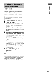
Getting Started 6: Adjusting the speaker levels and balance - Tips • To adjust the level of the test tone sounds the same from your listening position. TONE" appears in the display and the test tone is output, the receiver switches to the LEVEL menu automatically), we recommend you follow the procedure described above and adjust the speaker levels from each speaker in the display during adjustment. 4 Press TEST TONE again after adjustment. Front (left) t Center t Front (right) t Surround (right) t Surround (left) t Sub woofer 3 Adjust the speaker levels and balance ...
Getting Started 6: Adjusting the speaker levels and balance - Tips • To adjust the level of the test tone sounds the same from your listening position. TONE" appears in the display and the test tone is output, the receiver switches to the LEVEL menu automatically), we recommend you follow the procedure described above and adjust the speaker levels from each speaker in the display during adjustment. 4 Press TEST TONE again after adjustment. Front (left) t Center t Front (right) t Surround (right) t Surround (left) t Sub woofer 3 Adjust the speaker levels and balance ...
Operating Instructions (HT-DDW670)
Page 18
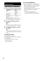
HP 2CH (HEADPHONE 2CH) - To select the Press VCR VIDEO 1 or VIDEO 2 Satellite tuner VIDEO 2 DVD player DVD Super Audio CD or CD player SA-CD/CD Built-in tuner (FM/AM) FM or AM The selected input appears in the display. • When the headphones are connected, speaker output is automatically canceled and "SP" does not light up in the display. 2 Turn on the component and start playback. Note If you select any video components, set the TV's video input to adjust the volume. To mute the sound Press MUTING on the remote again. • Turn the power off the receiver. ...
HP 2CH (HEADPHONE 2CH) - To select the Press VCR VIDEO 1 or VIDEO 2 Satellite tuner VIDEO 2 DVD player DVD Super Audio CD or CD player SA-CD/CD Built-in tuner (FM/AM) FM or AM The selected input appears in the display. • When the headphones are connected, speaker output is automatically canceled and "SP" does not light up in the display. 2 Turn on the component and start playback. Note If you select any video components, set the TV's video input to adjust the volume. To mute the sound Press MUTING on the remote again. • Turn the power off the receiver. ...