Operation Guide
Page 3
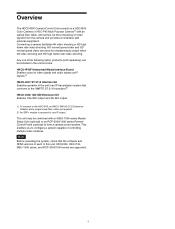
... Adaptor and a single-mode fiber cable are supported. 3 Note Before operating the system, check that conforms to the SMPTE ST 2110 standard.2) HKCU-4002 12G-SDI Extension Kit Enables 12G-SDI output and 6G-SDI output. 1) To connect to use IP output. HD normal speed video and SD normal speed video can be simultaneously output when 4K video shooting and HD high frame rate...
... Adaptor and a single-mode fiber cable are supported. 3 Note Before operating the system, check that conforms to the SMPTE ST 2110 standard.2) HKCU-4002 12G-SDI Extension Kit Enables 12G-SDI output and 6G-SDI output. 1) To connect to use IP output. HD normal speed video and SD normal speed video can be simultaneously output when 4K video shooting and HD high frame rate...

Operation Guide
Page 4
... Video Router Hub HDLA1500-series Large Lens Adaptor CAC-6 Return Video Selector LAN cable Lens (for communication with HDLA1500 series (Part No.: A-1128-405-A) b) Install NXLK-IP40F SDI-IP Converter Board (option). For advice on choosing devices, please contact your Sony representative or dealer. e) Install HKCU-IP43F (option) or HKCU-4001 (option) for studio camera) V-wedge shoe (supplied with...
... Video Router Hub HDLA1500-series Large Lens Adaptor CAC-6 Return Video Selector LAN cable Lens (for communication with HDLA1500 series (Part No.: A-1128-405-A) b) Install NXLK-IP40F SDI-IP Converter Board (option). For advice on choosing devices, please contact your Sony representative or dealer. e) Install HKCU-IP43F (option) or HKCU-4001 (option) for studio camera) V-wedge shoe (supplied with...
Operation Guide
Page 8
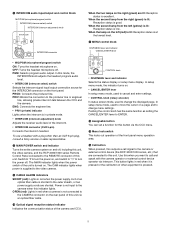
...pin) Connects the intercom headset. PGM: Selects program audio output. OPEN (red): Lights in red when the power supply cord of the unit is turned on . m Menu lock switch This locks out operation of the camera and CCU. To use a headset with the camera operator or external control device operator via an optical fiber cable... of other than an XLR 5-pin plug, consult a Sony service or sales representative. When the second lamp from the right (green) is lit: Reception status is good. ENG: Connects the engineer line. • PRIV (private) indicator Lights when the intercom is in red...
...pin) Connects the intercom headset. PGM: Selects program audio output. OPEN (red): Lights in red when the power supply cord of the unit is turned on . m Menu lock switch This locks out operation of the camera and CCU. To use a headset with the camera operator or external control device operator via an optical fiber cable... of other than an XLR 5-pin plug, consult a Sony service or sales representative. When the second lamp from the right (green) is lit: Reception status is good. ENG: Connects the engineer line. • PRIV (private) indicator Lights when the intercom is in red...
Operation Guide
Page 9
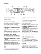
... is made by the return switch of the video camera. When 1 channel is set individually using the setup menu, or using an RCP-3000/1000 series unit, power is also supplied. Control signals are required. c 3G/HD SDI OUTPUT (SDI output) connector (SLOT1) (BNC-type) Used to output video signals from 9 Connect a LAN HUB (10BASE-T/ 100BASE-TX), using an optical fiber cable. h RETURN SDI IN 1/2 (3G...
... is made by the return switch of the video camera. When 1 channel is set individually using the setup menu, or using an RCP-3000/1000 series unit, power is also supplied. Control signals are required. c 3G/HD SDI OUTPUT (SDI output) connector (SLOT1) (BNC-type) Used to output video signals from 9 Connect a LAN HUB (10BASE-T/ 100BASE-TX), using an optical fiber cable. h RETURN SDI IN 1/2 (3G...

Operation Guide
Page 10
... results or setup menu of reference signal is (loop-through output is input, 10F BB on settings, contact a Sony service or sales representative. AC IN (AC power input) connector Use the specified AC power cord to connect to select the signal, contact a Sony service or sales representative. The HDCU4300 supports IP output of a single 4K signal or dual HD signals by the return switch of the...
... results or setup menu of reference signal is (loop-through output is input, 10F BB on settings, contact a Sony service or sales representative. AC IN (AC power input) connector Use the specified AC power cord to connect to select the signal, contact a Sony service or sales representative. The HDCU4300 supports IP output of a single 4K signal or dual HD signals by the return switch of the...

Operation Guide
Page 11
... is supported by installing an HKCU-4002 in the setup menu. HDCU4300 software version 1.50 or later is required. HKCU-4001 ST 2110 Interface Kit (Option) Note For safety, only a qualified technician with service training should perform tasks inside the unit. For details about installation, contact a Sony service or sales representative. 1 a 12G/6G-SDI output connectors These connectors are supported. The output...
... is supported by installing an HKCU-4002 in the setup menu. HDCU4300 software version 1.50 or later is required. HKCU-4001 ST 2110 Interface Kit (Option) Note For safety, only a qualified technician with service training should perform tasks inside the unit. For details about installation, contact a Sony service or sales representative. 1 a 12G/6G-SDI output connectors These connectors are supported. The output...

Operation Guide
Page 13
... Connection Type and BNC Connector Assignment" (page 17). CNA-1 Camera Control Network Adaptor Mouse Settings Device HDCU4300 HDC4300 Purpose HD system format setting Video format setting Video output format setting HD CUTOUT settings HD-PROMPTER output and HD TRUNK input settings Menu/Page Item SYSTEM OPERATION/ BASE FORMAT SYSTEM OPERATION/ 4K/HFR FORMAT SYSTEM OPERATION/ SLOT1 to the SZC-2001/ 2001M/2001W User's Guide...
... Connection Type and BNC Connector Assignment" (page 17). CNA-1 Camera Control Network Adaptor Mouse Settings Device HDCU4300 HDC4300 Purpose HD system format setting Video format setting Video output format setting HD CUTOUT settings HD-PROMPTER output and HD TRUNK input settings Menu/Page Item SYSTEM OPERATION/ BASE FORMAT SYSTEM OPERATION/ 4K/HFR FORMAT SYSTEM OPERATION/ SLOT1 to the SZC-2001/ 2001M/2001W User's Guide...

Operation Guide
Page 24
... Yes Yes PWS-100NM1 Connection Settings When an HKCU-IP43F is installed and a PWS-100NM1 IP Live System Manager station is supported. Trap Settings dialog Item Enable/Disable Name Network Interface Name IP Address Port Version Type Set value (defaults are underlined) Enable, Disable 0.0.0.0 Port sysName sysContact sysLocation Sub Agent List V1/V2c 161 - - - - Fixed value Fixed value 24 When set to 32 Meaning Fixed value Address for...
... Yes Yes PWS-100NM1 Connection Settings When an HKCU-IP43F is installed and a PWS-100NM1 IP Live System Manager station is supported. Trap Settings dialog Item Enable/Disable Name Network Interface Name IP Address Port Version Type Set value (defaults are underlined) Enable, Disable 0.0.0.0 Port sysName sysContact sysLocation Sub Agent List V1/V2c 161 - - - - Fixed value Fixed value 24 When set to 32 Meaning Fixed value Address for...

Operation Guide
Page 25
... value indication Displays the video output signal gain setting value (dB). k Shutter speed/Clear scan frequency indication Displays the shutter speed. l Shutter/ECS indication Displays the on , displays the clear scan frequency. e F-stop value indication Displays the lens F-stop value (iris value). Status Display The CCU system status can be monitored using the knob and levers in...
... value indication Displays the video output signal gain setting value (dB). k Shutter speed/Clear scan frequency indication Displays the shutter speed. l Shutter/ECS indication Displays the on , displays the clear scan frequency. e F-stop value indication Displays the lens F-stop value (iris value). Status Display The CCU system status can be monitored using the knob and levers in...

Operation Guide
Page 28
... Settings The menu screen is controlled using a video monitor connected to TOP in the MENU control block on , the CCU MENU page is displayed. ** CCU MENU ** cSYSTEM OPERATION VIDEO/MONITOR AUDIO/INTERCOM MAINTENANCE NETWORK DIAGNOSIS Menu name SYSTEM OPERATION VIDEO/MONITOR AUDIO/INTERCOM MAINTENANCE NETWORK DIAGNOSIS Description Input/output signal format and system-related settings Video-related settings...
... Settings The menu screen is controlled using a video monitor connected to TOP in the MENU control block on , the CCU MENU page is displayed. ** CCU MENU ** cSYSTEM OPERATION VIDEO/MONITOR AUDIO/INTERCOM MAINTENANCE NETWORK DIAGNOSIS Menu name SYSTEM OPERATION VIDEO/MONITOR AUDIO/INTERCOM MAINTENANCE NETWORK DIAGNOSIS Description Input/output signal format and system-related settings Video-related settings...

Operation Guide
Page 32
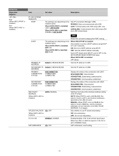
... DATA ASSIGNABLE SWITCH READ INSTALLED OPTIONS LASER DIODE ON BACKUP RETURN VF IP ADDRESS (N01) CNS SETTINGS (N02) TSL UMD (N03) NETWORKED MEDIA INTERFACE a) (N04) IP ADDRESS 2 b) (N04) NETWORK GENLOCK b) (N05) PTP STATUS b) (N06) IP LIVE a) b) (N05) a) (N07) b) IP ADDRESS SUBNET MASK DEFAULT GATEWAY MAC ADDRESS CNS MODE MCS MODE CCU NO MASTER IP ADDRESS TSL UMD PORT PORT NUMBER...
... DATA ASSIGNABLE SWITCH READ INSTALLED OPTIONS LASER DIODE ON BACKUP RETURN VF IP ADDRESS (N01) CNS SETTINGS (N02) TSL UMD (N03) NETWORKED MEDIA INTERFACE a) (N04) IP ADDRESS 2 b) (N04) NETWORK GENLOCK b) (N05) PTP STATUS b) (N06) IP LIVE a) b) (N05) a) (N07) b) IP ADDRESS SUBNET MASK DEFAULT GATEWAY MAC ADDRESS CNS MODE MCS MODE CCU NO MASTER IP ADDRESS TSL UMD PORT PORT NUMBER...

Operation Guide
Page 50
... identify the channel number of the CCU. -20, 0, +4 dBu Sets the AUDIO CH1 output level. -99 to 99 0 -20, 0, +4 dBu Sets the AUDIO CH2 output level. -99 to 99 0 50 The number of squares indicates the channel number so you can be used . (---), 20, 30, 40, 50, 60 dB (---): Displayed when a camera is for Links 1 to check the connections. AES/EBU: Outputs the...
... identify the channel number of the CCU. -20, 0, +4 dBu Sets the AUDIO CH1 output level. -99 to 99 0 -20, 0, +4 dBu Sets the AUDIO CH2 output level. -99 to 99 0 50 The number of squares indicates the channel number so you can be used . (---), 20, 30, 40, 50, 60 dB (---): Displayed when a camera is for Links 1 to check the connections. AES/EBU: Outputs the...

Operation Guide
Page 51
... switch on the front panel is selected in SYSTEM I /F. (Display only) Sets the engineer line intercom system. -99 to be used. ENABLE: Private operation DISABLE(SET TO ENG): Same function as PROD position. CARBON: Carbon microphone (power supply, 20 dB gain) ECM: Electret condenser microphone (power supply, 40 dB gain) DYNAMIC: Dynamic microphone (no power supply, 60 dB gain) Sets the headset microphone connected...
... switch on the front panel is selected in SYSTEM I /F. (Display only) Sets the engineer line intercom system. -99 to be used. ENABLE: Private operation DISABLE(SET TO ENG): Same function as PROD position. CARBON: Carbon microphone (power supply, 20 dB gain) ECM: Electret condenser microphone (power supply, 40 dB gain) DYNAMIC: Dynamic microphone (no power supply, 60 dB gain) Sets the headset microphone connected...

Operation Guide
Page 55
... USB flash drive. NORMAL: Normal-speed signal HFR LINK: HFR signal 1LINK (steady image can be displayed. Sets the subnet mask. Displays the LAN port being used as the image to 255.255.255.255 DISABLE, ENABLE LAN-COM PORT NUMBER PACKET STATUS 8900 NOT RECEIVED, RECEIVED Sets the IP address. Sets the function to be used (Fixed to the camera ON/OFF. Reads the installation key...
... USB flash drive. NORMAL: Normal-speed signal HFR LINK: HFR signal 1LINK (steady image can be displayed. Sets the subnet mask. Displays the LAN port being used as the image to 255.255.255.255 DISABLE, ENABLE LAN-COM PORT NUMBER PACKET STATUS 8900 NOT RECEIVED, RECEIVED Sets the IP address. Sets the function to be used (Fixed to the camera ON/OFF. Reads the installation key...

Operation Guide
Page 56
... selected network interface. When DHCP disabled: Sets and displays the default gateway IP address for the selected network interface. LINK SPEED 25G FEC 10G, 25G, ----- When DHCP enabled: Displays the IP address assigned using DHCP for setting the IP address. When DHCP disabled: Displays the subnet mask setting for 25G. (CL74) Note Set to the port setting of the IP switch to be connected. 56 Fixed to...
... selected network interface. When DHCP disabled: Sets and displays the default gateway IP address for the selected network interface. LINK SPEED 25G FEC 10G, 25G, ----- When DHCP enabled: Displays the IP address assigned using DHCP for setting the IP address. When DHCP disabled: Displays the subnet mask setting for 25G. (CL74) Note Set to the port setting of the IP switch to be connected. 56 Fixed to...

Operation Guide
Page 57
...: Synchronizing LOCKED: Synchronized Displays the port on which to the master. Sets the domain number. TWO-STEP: Sent in Follow-up message rate Delay request message rate Delay response message rate Displays the network status. Selects the port for which PTP is supported. Item PORT N05 (When HKCU-4001 is installed) NETWORK GENLOCK PROFILE DOMAIN NUMBER Set value LAN1, LAN2 DISABLE, ENABLE ST2059-2 0 to 127, 127...
...: Synchronizing LOCKED: Synchronized Displays the port on which to the master. Sets the domain number. TWO-STEP: Sent in Follow-up message rate Delay request message rate Delay response message rate Displays the network status. Selects the port for which PTP is supported. Item PORT N05 (When HKCU-4001 is installed) NETWORK GENLOCK PROFILE DOMAIN NUMBER Set value LAN1, LAN2 DISABLE, ENABLE ST2059-2 0 to 127, 127...
Operation Guide
Page 58
... unit after changing the PORT setting. DHCP The settings vary depending on the NETWORKED MEDIA INTERFACE page. Set to OFF (fixed) when DHCP is set the LSM IP address using LAN1 only. CONNECTING: Establishing communication. CONNECTING: Establishing communication. MANUAL: When PORT is set to OFF on the installed option. When the LAN1 or LAN2 link speed is 10G, this option is installed) Item Set value Description IP LIVE...
... unit after changing the PORT setting. DHCP The settings vary depending on the NETWORKED MEDIA INTERFACE page. Set to OFF (fixed) when DHCP is set the LSM IP address using LAN1 only. CONNECTING: Establishing communication. CONNECTING: Establishing communication. MANUAL: When PORT is set to OFF on the installed option. When the LAN1 or LAN2 link speed is 10G, this option is installed) Item Set value Description IP LIVE...
Operation Guide
Page 63
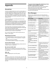
... LEGACY FORCE LEGACY is set to REMOTE connector) power supply error CCU:PS TEMP WARNING Power supply unit temperature error CCU:DVP FAN STOP DVP board fan stopped CCU:OPTICAL CONDITION ERROR Light sensor level on parts replacement, contact your fingers or sharp objects. For severe dirt, use a soft cloth steeped in this unit. It is recommended that the portable communications devices near sources of...
... LEGACY FORCE LEGACY is set to REMOTE connector) power supply error CCU:PS TEMP WARNING Power supply unit temperature error CCU:DVP FAN STOP DVP board fan stopped CCU:OPTICAL CONDITION ERROR Light sensor level on parts replacement, contact your fingers or sharp objects. For severe dirt, use a soft cloth steeped in this unit. It is recommended that the portable communications devices near sources of...
Operation Guide
Page 65
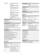
...+/SFP28 transceiver module) For information about the supported SFP+ and SFP28 transceiver modules (e.g. Supplied accessories Flat cable 30-pin (1) Coaxial cable 30-pin (1) Coaxial cable 40-pin (1) Power supply harness (1) Screws M3×8 (6) Screws M2.6×5 (2) Wire saddle (4) Protective tape (1) Label (1) Operating Instructions (1) Related devices OTM-10GSR1 SFP+ Transceiver Module OTM-25GSR1 SFP28 Transceiver Module 65 OTM-10GSR1), contact your Sony sales or service representative.
...+/SFP28 transceiver module) For information about the supported SFP+ and SFP28 transceiver modules (e.g. Supplied accessories Flat cable 30-pin (1) Coaxial cable 30-pin (1) Coaxial cable 40-pin (1) Power supply harness (1) Screws M3×8 (6) Screws M2.6×5 (2) Wire saddle (4) Protective tape (1) Label (1) Operating Instructions (1) Related devices OTM-10GSR1 SFP+ Transceiver Module OTM-25GSR1 SFP28 Transceiver Module 65 OTM-10GSR1), contact your Sony sales or service representative.

Operation Guide
Page 66
...-SDI switchable Supplied accessories 40-pin cable (1) Harness (2) Operating Instructions (1) Design and specifications are subject to access the unit. Depending on the operating environment, unauthorized third parties on the network may be sure to inform you of the content of these licenses, see the PDF files in the "License" folder of license contracts between Sony and the software copyright holders, this product uses open software.
...-SDI switchable Supplied accessories 40-pin cable (1) Harness (2) Operating Instructions (1) Design and specifications are subject to access the unit. Depending on the operating environment, unauthorized third parties on the network may be sure to inform you of the content of these licenses, see the PDF files in the "License" folder of license contracts between Sony and the software copyright holders, this product uses open software.
