Service Manual
Page 1
...European, Korean, Argentine and Thai models: AC 220 V 240 V, 50/60 Hz Other models: AC 120 V 240 V, 50/60 Hz Power consumption HCD-SLK2i: 80 W HCD-SLK1i: 60 W Dimensions (W/H/D) (excl. USB section (USB) port: Type A Maximum current: 500 mA Memory card section Multi memory card slot: Compatible ... iPod nano 3rd generation (video) iPod classic 80 GB iPod nano 2nd generation (aluminum) DVD RECEIVER 9-889-894-01 2010F05-1 © 2010.06 Sony Corporation Audio&Video Business Group Published by Sony Techno Create Corporation iPod models You can use the following measured at AC 120 V 240 ...
...European, Korean, Argentine and Thai models: AC 220 V 240 V, 50/60 Hz Other models: AC 120 V 240 V, 50/60 Hz Power consumption HCD-SLK2i: 80 W HCD-SLK1i: 60 W Dimensions (W/H/D) (excl. USB section (USB) port: Type A Maximum current: 500 mA Memory card section Multi memory card slot: Compatible ... iPod nano 3rd generation (video) iPod classic 80 GB iPod nano 2nd generation (aluminum) DVD RECEIVER 9-889-894-01 2010F05-1 © 2010.06 Sony Corporation Audio&Video Business Group Published by Sony Techno Create Corporation iPod models You can use the following measured at AC 120 V 240 ...

Service Manual
Page 2
... LES NUMÉROS SONT DONNÉS DANS CE MANUEL OU DANS LES SUPPLÉMENTS PUBLIÉS PAR SONY. 2 HCD-SLK1i/SLK2i Manufactured under license. ® This product is an official DivX certified product. ATTENTION AU COMPOSANT AYANT RAPPORT ... PROVIDER LICENSED BY MPEG LA TO PROVIDE MPEG-4 VIDEO. A commercial leakage tester, such as described below. "DVD+RW," "DVD-RW," "DVD+R," "DVD VIDEO," and the "CD" logos are trademarks of Sony Corporation. MPEG Layer-3 audio coding technology and patents licensed from Dolby Laboratories. This appliance is classified as a ...
... LES NUMÉROS SONT DONNÉS DANS CE MANUEL OU DANS LES SUPPLÉMENTS PUBLIÉS PAR SONY. 2 HCD-SLK1i/SLK2i Manufactured under license. ® This product is an official DivX certified product. ATTENTION AU COMPOSANT AYANT RAPPORT ... PROVIDER LICENSED BY MPEG LA TO PROVIDE MPEG-4 VIDEO. A commercial leakage tester, such as described below. "DVD+RW," "DVD-RW," "DVD+R," "DVD VIDEO," and the "CD" logos are trademarks of Sony Corporation. MPEG Layer-3 audio coding technology and patents licensed from Dolby Laboratories. This appliance is classified as a ...

Service Manual
Page 3
... DISPLAY Board Section 67 5-5. Front Panel Section 68 5-6. SERVICING NOTES 4 2. Top Panel Block 10 2-3. Main Chassis Block 11 2-5. MAIN Board 12 2-6. DVD Mechanism Deck Block 13 2-9. Belt (MOT 15 2-12. AUDIO INPUT Section 22 4-3. Block Diagram - Schematic Diagram - AUDIO IN/OUT Section -....... 38 4-...25. Block Diagram - Optical Pick-up Block (KHM-313CAB 15 2-11. LCD Board 36 4-16. Block Diagram - HCD-SLK1i/SLK2i TABLE OF CONTENTS 1. DISASSEMBLY 2-1. Switching Regulator Block 12 2-7. Schematic Diagram - Schematic Diagram - EXPLODED VIEWS 5-1.
... DISPLAY Board Section 67 5-5. Front Panel Section 68 5-6. SERVICING NOTES 4 2. Top Panel Block 10 2-3. Main Chassis Block 11 2-5. MAIN Board 12 2-6. DVD Mechanism Deck Block 13 2-9. Belt (MOT 15 2-12. AUDIO INPUT Section 22 4-3. Block Diagram - Schematic Diagram - AUDIO IN/OUT Section -....... 38 4-...25. Block Diagram - Optical Pick-up Block (KHM-313CAB 15 2-11. LCD Board 36 4-16. Block Diagram - HCD-SLK1i/SLK2i TABLE OF CONTENTS 1. DISASSEMBLY 2-1. Switching Regulator Block 12 2-7. Schematic Diagram - Schematic Diagram - EXPLODED VIEWS 5-1.

Service Manual
Page 4
HCD-SLK1i/SLK2i SECTION 1 SERVICING NOTES NOTES ON HANDLING THE OPTICAL PICK-UP BLOCK OR BASE UNIT The laser diode in the optical pick-up block may ...
HCD-SLK1i/SLK2i SECTION 1 SERVICING NOTES NOTES ON HANDLING THE OPTICAL PICK-UP BLOCK OR BASE UNIT The laser diode in the optical pick-up block may ...

Service Manual
Page 5
Switching Regulator (Conductor Side) - 800 :/2 W C201 C202 T101 800 :/2 W • Switching regulator (C201) (for HCD-SLK2i) Both ends of respective capacitors. - CAPACITOR ELECTRICAL DISCHARGE PROCESSING When checking the board, the electrical discharge is necessary for HCD-SLK1i) Both ends of respective capacitor. - Switching Regulator (Conductor Side) - 800 :/2 W C201 T101 HCD-SLK1i/SLK2i 5 Connect the resistors referring to the figure below. • Switching regulator (C201, C202) (for the electric shock prevention.
Switching Regulator (Conductor Side) - 800 :/2 W C201 C202 T101 800 :/2 W • Switching regulator (C201) (for HCD-SLK2i) Both ends of respective capacitors. - CAPACITOR ELECTRICAL DISCHARGE PROCESSING When checking the board, the electrical discharge is necessary for HCD-SLK1i) Both ends of respective capacitor. - Switching Regulator (Conductor Side) - 800 :/2 W C201 T101 HCD-SLK1i/SLK2i 5 Connect the resistors referring to the figure below. • Switching regulator (C201, C202) (for the electric shock prevention.

Service Manual
Page 6
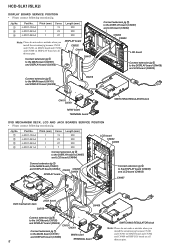
Please rotate the pully in the direction of the arrow after removing mechanism deck, and eject the disc. IP BOARD SERVICE POSITION Note: Neither the wire from a set referring to "SECTION 2 DISASSEMBLY". DVD mechanism block bottom view - HCD-SLK1i/SLK2i HOW TO EJECT THE DISC WHEN POWER SWITCH TURNS OFF Note: Please take out the DVD mechanism block from switching regulator nor the fan cable must loosen. disc - fan motor wire from switching regulator fan cable DISPLAY board IP board 6
Please rotate the pully in the direction of the arrow after removing mechanism deck, and eject the disc. IP BOARD SERVICE POSITION Note: Neither the wire from a set referring to "SECTION 2 DISASSEMBLY". DVD mechanism block bottom view - HCD-SLK1i/SLK2i HOW TO EJECT THE DISC WHEN POWER SWITCH TURNS OFF Note: Please take out the DVD mechanism block from switching regulator nor the fan cable must loosen. disc - fan motor wire from switching regulator fan cable DISPLAY board IP board 6

Service Manual
Page 7
Connect extension jig 1 to the MAIN board (CN301) and DISPLAY board (CN302) HCD-SLK1i/SLK2i CN302 CN408 DISPLAY board Connect extension jig 1 to the MAIN board (CN101) and DISPLAY board (CN408) CN101 CN301 MAIN board TERMINAL board SWITCHING REGULATOR 7 ...
Connect extension jig 1 to the MAIN board (CN301) and DISPLAY board (CN302) HCD-SLK1i/SLK2i CN302 CN408 DISPLAY board Connect extension jig 1 to the MAIN board (CN101) and DISPLAY board (CN408) CN101 CN301 MAIN board TERMINAL board SWITCHING REGULATOR 7 ...
Service Manual
Page 8
...) CN904 CN903 LCD board Connect extension jig 3 to the DISPLAY board (CN406) and LCD board (CN903) CN101 CN301 MAIN board TERMINAL board SWITCHING REGULATOR block DVD MECHANISM DECK, LCD AND JACK BOARDS SERVICE POSITION • Please connect following extension jig. Jig No. 1 2 3 4 Part No. J-2501-102-A J-2501-245-A J-2501...when you install the extention jig because CN101 and CN301 on MAIN board and CN302 and CN408 on DISPLAY board are all thirteen pins. HCD-SLK1i/SLK2i DISPLAY BOARD SERVICE POSITION • Please connect following extension jig. Jig No. 1 2 3 Part No.
...) CN904 CN903 LCD board Connect extension jig 3 to the DISPLAY board (CN406) and LCD board (CN903) CN101 CN301 MAIN board TERMINAL board SWITCHING REGULATOR block DVD MECHANISM DECK, LCD AND JACK BOARDS SERVICE POSITION • Please connect following extension jig. Jig No. 1 2 3 4 Part No. J-2501-102-A J-2501-245-A J-2501...when you install the extention jig because CN101 and CN301 on MAIN board and CN302 and CN408 on DISPLAY board are all thirteen pins. HCD-SLK1i/SLK2i DISPLAY BOARD SERVICE POSITION • Please connect following extension jig. Jig No. 1 2 3 Part No.

Service Manual
Page 9
MAIN BOARD (Page 12) 2-6. LCD BOARD (Page 16) 2-13. OPTICAL PICK-UP BLOCK (KHM-313CAB) (Page 15) 2-11. REAR CASE BLOCK (Page 10) 2-4. DISPLAY BOARD (Page 14) 2-10. BELT (MOT) (Page 15) 9 MAIN CHASSIS BLOCK (Page 11) 2-5. DVD MECHANISM DECK BLOCK (Page 13) 2-12. LCD MODULE (Page 16) 2-9. SECTION 2 DISASSEMBLY • This set can be disassembled in the order shown below. 2-1. COVER (CDM) BLOCK (Page 13) 2-8. TOP PANEL BLOCK (Page 10) 2-3. SWITCHING REGULATOR BLOCK (Page 12) 2-7. DISASSEMBLY FLOW SET HCD-SLK1i/SLK2i 2-2.
MAIN BOARD (Page 12) 2-6. LCD BOARD (Page 16) 2-13. OPTICAL PICK-UP BLOCK (KHM-313CAB) (Page 15) 2-11. REAR CASE BLOCK (Page 10) 2-4. DISPLAY BOARD (Page 14) 2-10. BELT (MOT) (Page 15) 9 MAIN CHASSIS BLOCK (Page 11) 2-5. DVD MECHANISM DECK BLOCK (Page 13) 2-12. LCD MODULE (Page 16) 2-9. SECTION 2 DISASSEMBLY • This set can be disassembled in the order shown below. 2-1. COVER (CDM) BLOCK (Page 13) 2-8. TOP PANEL BLOCK (Page 10) 2-3. SWITCHING REGULATOR BLOCK (Page 12) 2-7. DISASSEMBLY FLOW SET HCD-SLK1i/SLK2i 2-2.

Service Manual
Page 10
... screws (TP) - Rear view - 2-3. REAR CASE BLOCK 1 two flat head screws (TP) 5 four screws (BVTP2.6) 2 support (bushing) 3 two flat head screws (TP) 6 claw 4 four screws (SLK1i: BTT4 u 8/SLK2i: hook) 9 rear case block 8 7 6 claw 3 two flat head screws (TP) sheet Note: Please spread a sheet under a set not to injure front panel...
... screws (TP) - Rear view - 2-3. REAR CASE BLOCK 1 two flat head screws (TP) 5 four screws (BVTP2.6) 2 support (bushing) 3 two flat head screws (TP) 6 claw 4 four screws (SLK1i: BTT4 u 8/SLK2i: hook) 9 rear case block 8 7 6 claw 3 two flat head screws (TP) sheet Note: Please spread a sheet under a set not to injure front panel...

Service Manual
Page 11
...) (CN104) qd screw (BVTP3 u 8) 8 wire (flat type) (13 core) (CN103) sheet Note 1: Please spread a sheet under a set not to injure front panel. MAIN CHASSIS BLOCK - HCD-SLK1i/SLK2i 2-4. qh screw (BVTP2.6) qj wire qd screw (BVTP3 u 8) qf wire (GND) 5 Lift up the lead pin. MAIN board wire from switching regulator 11 Rear...
...) (CN104) qd screw (BVTP3 u 8) 8 wire (flat type) (13 core) (CN103) sheet Note 1: Please spread a sheet under a set not to injure front panel. MAIN CHASSIS BLOCK - HCD-SLK1i/SLK2i 2-4. qh screw (BVTP2.6) qj wire qd screw (BVTP3 u 8) qf wire (GND) 5 Lift up the lead pin. MAIN board wire from switching regulator 11 Rear...

Service Manual
Page 12
HCD-SLK1i/SLK2i 2-5. sheet Note: Please spread a sheet under a set not to the fan motor. 5 wire (flat type) (11 core) (CN302) (AEP)/ wire (flat type) (9 core) (CN303) (...
HCD-SLK1i/SLK2i 2-5. sheet Note: Please spread a sheet under a set not to the fan motor. 5 wire (flat type) (11 core) (CN302) (AEP)/ wire (flat type) (9 core) (CN303) (...

Service Manual
Page 13
.... 9 wire (flat type) (24 core) (CN001) 5 two claws 8 Solder the short-land. 7 FFC holder 4 2 connector (CN202) 1 wire (flat type) (7 core) (CN201) 6 two claws 0 DVD mechanism deck block Note 2: When assembling the optical pick-up block, remove the solder of short-land after connecting the wire (flat type) (24 core... 4 four screws (BVTP2.6) 6 cover (CDM) block 3 wire (flat type) (23 core) (CN407) 1 wire (flat type) (11 core) (CN412) 2 wire (flat type) (27 core) (CN406) - DVD mechanism deck block bottom view - 13 sheet Note: Please spread a sheet under a set not to injure front panel...
.... 9 wire (flat type) (24 core) (CN001) 5 two claws 8 Solder the short-land. 7 FFC holder 4 2 connector (CN202) 1 wire (flat type) (7 core) (CN201) 6 two claws 0 DVD mechanism deck block Note 2: When assembling the optical pick-up block, remove the solder of short-land after connecting the wire (flat type) (24 core... 4 four screws (BVTP2.6) 6 cover (CDM) block 3 wire (flat type) (23 core) (CN407) 1 wire (flat type) (11 core) (CN412) 2 wire (flat type) (27 core) (CN406) - DVD mechanism deck block bottom view - 13 sheet Note: Please spread a sheet under a set not to injure front panel...

Service Manual
Page 14
DISPLAY BOARD 2 ferrite core (US, Canadian) 4 wire (flat type) (11 core) (CN411) 1 connector (CN301) 5 eight screws (BVTP2.6) 3 wire (flat type) (15 core) (CN002) 6 shield (MS) 0 radiation sheet qa DISPLAY board 9 ground plate (USB) 7 8 cover (CDM) 14 HCD-SLK1i/SLK2i 2-9.
DISPLAY BOARD 2 ferrite core (US, Canadian) 4 wire (flat type) (11 core) (CN411) 1 connector (CN301) 5 eight screws (BVTP2.6) 3 wire (flat type) (15 core) (CN002) 6 shield (MS) 0 radiation sheet qa DISPLAY board 9 ground plate (USB) 7 8 cover (CDM) 14 HCD-SLK1i/SLK2i 2-9.

Service Manual
Page 16
HCD-SLK1i/SLK2i 2-12. LCD MODULE 6 two screws (BVTP2.6) 1 wire (flat type) (11 core) (KEY-RIGHT board: CN263, KEY-LEFT board: CN262) 2 three screws (BVTP2.6) 8 wire (GND) 9 ...
HCD-SLK1i/SLK2i 2-12. LCD MODULE 6 two screws (BVTP2.6) 1 wire (flat type) (11 core) (KEY-RIGHT board: CN263, KEY-LEFT board: CN262) 2 three screws (BVTP2.6) 8 wire (GND) 9 ...

Service Manual
Page 17
SECTION 3 TEST MODE HCD-SLK1i/SLK2i COLD RESET Reset the system to turn on the system. 2. Procedure: 1. Touch the [M], [m], [ Press the [?/1] button to its factory default settings.
SECTION 3 TEST MODE HCD-SLK1i/SLK2i COLD RESET Reset the system to turn on the system. 2. Procedure: 1. Touch the [M], [m], [ Press the [?/1] button to its factory default settings.

Service Manual
Page 18
HCD-SLK1i/SLK2i DISC ANTITHEFT LOCK This mode is used to unable to turn on the system. 2. Touch the [M], [m], [ Press the [?/1] button to take sample disc out of disc slot in the shop. Touch the [HOME] sensor. 3. Procedure: 1.
HCD-SLK1i/SLK2i DISC ANTITHEFT LOCK This mode is used to unable to turn on the system. 2. Touch the [M], [m], [ Press the [?/1] button to take sample disc out of disc slot in the shop. Touch the [HOME] sensor. 3. Procedure: 1.

Service Manual
Page 19
HCD-SLK1i/SLK2i 1-1. Procedure: 1. Drive Manual Operation 1. Servo Control 2. MIRR time Adjust 0. Track Gain Adjust: 3. Focus Balance Adjust:...please follow the following screen appears on the remote commander. Procedure: 1. From the Top Menu of DVD and CD from hexadecimal to Top Menu 3. You can check the total time when the laser ...45 [Next] Next Page [Prev] Prev Page [O] Return to execute IOP measurement, the following three blocks. Enter the DVD service mode. 2. Select "2. The screen will appear as shown. Track/Layer Jump 3. Manual Adjustment 4. Return to ...
HCD-SLK1i/SLK2i 1-1. Procedure: 1. Drive Manual Operation 1. Servo Control 2. MIRR time Adjust 0. Track Gain Adjust: 3. Focus Balance Adjust:...please follow the following screen appears on the remote commander. Procedure: 1. From the Top Menu of DVD and CD from hexadecimal to Top Menu 3. You can check the total time when the laser ...45 [Next] Next Page [Prev] Prev Page [O] Return to execute IOP measurement, the following three blocks. Enter the DVD service mode. 2. Select "2. The screen will appear as shown. Track/Layer Jump 3. Manual Adjustment 4. Return to ...

Service Manual
Page 20
...) : Ver. Clear the Laser Hour Press [ DISPLAY] button and then press [CLEAR] button on the remote commander. Emg. History Check Laser Hours CD 0h 0min DVD 0h 0min 01. 01 05 04 04 00 00 00 00 02. 02 02 01 01 00 00 00 00 00 92 46 00 00... 00 23 45 00 A9 4B 00 00 00 23 45 [Next] Next Page [Prev] Prev Page [O] Return to Top Menu 1-2-3. HCD-SLK1i/SLK2i 52: Open kick spindle error 51: Spindle stop error 60: Focus on -screen display. Emg. CHECK VERSION INFORMATION To check the version information, please...
...) : Ver. Clear the Laser Hour Press [ DISPLAY] button and then press [CLEAR] button on the remote commander. Emg. History Check Laser Hours CD 0h 0min DVD 0h 0min 01. 01 05 04 04 00 00 00 00 02. 02 02 01 01 00 00 00 00 00 92 46 00 00... 00 23 45 00 A9 4B 00 00 00 23 45 [Next] Next Page [Prev] Prev Page [O] Return to Top Menu 1-2-3. HCD-SLK1i/SLK2i 52: Open kick spindle error 51: Spindle stop error 60: Focus on -screen display. Emg. CHECK VERSION INFORMATION To check the version information, please...

Service Manual
Page 21
...CD) Q003 (1/2) REG02 AUTO POWER CONTROL (FOR DVD) Q003 (2/2) 17 LDO1 18 LDO2 RF AMP, SERVO DSP, DVD/CD DECODER IC005 MSW VR (780) VR (650) CD ON SWITCH Q001 (1/2) DVD ON SWITCH Q001 (2/2) Q002 VCC FCS+ FCSTRK+ ...FOO 24 TRO 21 FMO 20 DMO 128 SPFG 87 88 35 41 40 43 IFBSY IFCS# IFSDI IFSDO IFSCK PRST# HCD-SLK1i/SLK2i ASDATA0 120 ACLK 114 ABCK 115 ALRCK 119 CVBS 99 AUDIO D/A CONVERTER IC301 1 SDATA 4 MCLK 2 SCLK 3 ...2 SO 5 SI 6 SCK R-ch is omitted due to same as L-ch. OCSW1 CKSW1 TRG-SW HCD-SLK1i/SLK2i 25 LOADING 16 24 MOTOR DRIVE 17 44 REV 45 FWD 43 OCSW1 42 CKSW1 6 TRG-SW ...
...CD) Q003 (1/2) REG02 AUTO POWER CONTROL (FOR DVD) Q003 (2/2) 17 LDO1 18 LDO2 RF AMP, SERVO DSP, DVD/CD DECODER IC005 MSW VR (780) VR (650) CD ON SWITCH Q001 (1/2) DVD ON SWITCH Q001 (2/2) Q002 VCC FCS+ FCSTRK+ ...FOO 24 TRO 21 FMO 20 DMO 128 SPFG 87 88 35 41 40 43 IFBSY IFCS# IFSDI IFSDO IFSCK PRST# HCD-SLK1i/SLK2i ASDATA0 120 ACLK 114 ABCK 115 ALRCK 119 CVBS 99 AUDIO D/A CONVERTER IC301 1 SDATA 4 MCLK 2 SCLK 3 ...2 SO 5 SI 6 SCK R-ch is omitted due to same as L-ch. OCSW1 CKSW1 TRG-SW HCD-SLK1i/SLK2i 25 LOADING 16 24 MOTOR DRIVE 17 44 REV 45 FWD 43 OCSW1 42 CKSW1 6 TRG-SW ...


