
Service Manual
Page 1
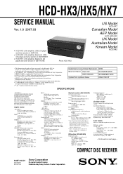
....1 kHz CD player section System: Compact disc and digital audio system Laser Diode Properties Emission duration: continuous Laser Output*: Less than 90 dB Tuner section FM stereo, FM/AM superheterodyne tuner FM tuner section: Tuning range US, Canadian models: 87.5 - 108.0 MHz (100 kHz step) Other models: 87.5 - 108.0 MHz (50 kHz step) Antenna: FM lead antenna Antenna terminals: 75 ohms unbalanced Intermediate frequency: 10.7 MHz - HCD-HX7 - HCD-HX3/HX5/HX7 SERVICE MANUAL Ver...
....1 kHz CD player section System: Compact disc and digital audio system Laser Diode Properties Emission duration: continuous Laser Output*: Less than 90 dB Tuner section FM stereo, FM/AM superheterodyne tuner FM tuner section: Tuning range US, Canadian models: 87.5 - 108.0 MHz (100 kHz step) Other models: 87.5 - 108.0 MHz (50 kHz step) Antenna: FM lead antenna Antenna terminals: 75 ohms unbalanced Intermediate frequency: 10.7 MHz - HCD-HX7 - HCD-HX3/HX5/HX7 SERVICE MANUAL Ver...
Service Manual
Page 2
... VOM that have an accurate low-voltage scale. A commercial leakage tester, such as described below. A. Follow the manufacturers' instructions to check AC leakage. COMPONENTS IDENTIFIED BY MARK 0 OR DOTTED LINE WITH MARK 0 ON THE SCHEMATIC DIAGRAMS AND IN THE PARTS LIST ARE CRITICAL TO SAFE OPERATION. HCD-HX3/HX5/HX7 AM tuner section: Tuning range US, Canadian models: 530 - 1,710 kHz (with 10...
... VOM that have an accurate low-voltage scale. A commercial leakage tester, such as described below. A. Follow the manufacturers' instructions to check AC leakage. COMPONENTS IDENTIFIED BY MARK 0 OR DOTTED LINE WITH MARK 0 ON THE SCHEMATIC DIAGRAMS AND IN THE PARTS LIST ARE CRITICAL TO SAFE OPERATION. HCD-HX3/HX5/HX7 AM tuner section: Tuning range US, Canadian models: 530 - 1,710 kHz (with 10...
Service Manual
Page 4
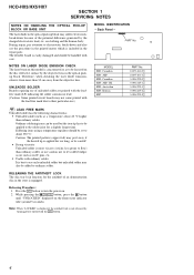
... objective lens in the repair parts. RELEASING THE ANTITHEFT LOCK The disc tray lock function for a slightly longer time. The flexible board is easily damaged and should be careful! • Strong viscosity Unleaded solder is more viscou-s (sticky, less prone to ordinary solder. HCD-HX3/HX5/HX7 SECTION 1 SERVICING NOTES NOTES ON HANDLING THE OPTICAL PICK-UP BLOCK OR...
... objective lens in the repair parts. RELEASING THE ANTITHEFT LOCK The disc tray lock function for a slightly longer time. The flexible board is easily damaged and should be careful! • Strong viscosity Unleaded solder is more viscou-s (sticky, less prone to ordinary solder. HCD-HX3/HX5/HX7 SECTION 1 SERVICING NOTES NOTES ON HANDLING THE OPTICAL PICK-UP BLOCK OR...

Service Manual
Page 5
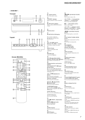
... display. ql REPEAT/FM MODE button Press to listen to delete a pre-programmed track or file. Battery compartment lid wa CLEAR button Press to a disc, a single track or file repeatedly. ws TUNER MEMORY button Press to select the AUDIO IN function. Remote: N (play /pause) button Press to tune in a track or file. Unit: AUDIO IN button Press to preset the radio station. qs SEARCH button Press to select the FM reception mode (monaural or stereo...
... display. ql REPEAT/FM MODE button Press to listen to delete a pre-programmed track or file. Battery compartment lid wa CLEAR button Press to a disc, a single track or file repeatedly. ws TUNER MEMORY button Press to select the AUDIO IN function. Remote: N (play /pause) button Press to tune in a track or file. Unit: AUDIO IN button Press to preset the radio station. qs SEARCH button Press to select the FM reception mode (monaural or stereo...

Service Manual
Page 6
...) button Press to select the tuning mode. Remote: USB button Press to select the USB function. Remote: N (play /pause) butt on Press to select the CD function. Press to start or pause playback of an optional USB device (Digital music player or USB storage media). qf ENTER button Press to select the sound effect. qj Sound buttons Unit: DSGX button Remote: EQ button Press to enter the settings. HCD-HX3/HX5/HX7 - Press to preset the radio station. wd TUNER...
...) button Press to select the tuning mode. Remote: USB button Press to select the USB function. Remote: N (play /pause) butt on Press to select the CD function. Press to start or pause playback of an optional USB device (Digital music player or USB storage media). qf ENTER button Press to select the sound effect. qj Sound buttons Unit: DSGX button Remote: EQ button Press to enter the settings. HCD-HX3/HX5/HX7 - Press to preset the radio station. wd TUNER...
Service Manual
Page 7
.... 6 Unit: VOLUME control Remote: VOLUME +/- Remote: n (play mode of a disc. TUNER/BAND button Press to select the CD function. qa Unit: x/CANCEL (stop/cancel) butt on the system. 2 STANDBY indicator Lights up when the system is turned off. 3 BLUETOOTH indicator Lights up when the Bluetooth function is active. 4 Remote sensor 5 BLUETOOTH OPR button Press to tune in a track or file. HCD-HX7 - button Turn or press to adjust the volume. 7 AUDIO IN jack Connect to an optional audio component. 8 PHONES jack Connect the...
.... 6 Unit: VOLUME control Remote: VOLUME +/- Remote: n (play mode of a disc. TUNER/BAND button Press to select the CD function. qa Unit: x/CANCEL (stop/cancel) butt on the system. 2 STANDBY indicator Lights up when the system is turned off. 3 BLUETOOTH indicator Lights up when the Bluetooth function is active. 4 Remote sensor 5 BLUETOOTH OPR button Press to tune in a track or file. HCD-HX7 - button Turn or press to adjust the volume. 7 AUDIO IN jack Connect to an optional audio component. 8 PHONES jack Connect the...

Service Manual
Page 8
... the power cord or if a power failure occurs. HCD-HX3 - HCD-HX5 - If the current mode appears on the display 1 Play/Pause 2 DSGX 3 Tuner reception mode Tuner reception 4 Text information 5 Audio format 6 Play mode 7 Timer - The clock is off Press DISPLAY. HCD-HX3/HX5/HX7 - and then press ENTER. 3 Press ./> repeatedly to set the minutes. Information on the display, press ./> repeatedly to select "CLOCK SET?" Setting the clock Use buttons on the remote to set the...
... the power cord or if a power failure occurs. HCD-HX3 - HCD-HX5 - If the current mode appears on the display 1 Play/Pause 2 DSGX 3 Tuner reception mode Tuner reception 4 Text information 5 Audio format 6 Play mode 7 Timer - The clock is off Press DISPLAY. HCD-HX3/HX5/HX7 - and then press ENTER. 3 Press ./> repeatedly to set the minutes. Information on the display, press ./> repeatedly to select "CLOCK SET?" Setting the clock Use buttons on the remote to set the...

Service Manual
Page 15
... set the CD disc. 3. CD SHIP MODE & MEMORY CLEAR This mode is displayed on the fluorescent indicator tube, the ship mode is reset. Turn the [VOLUME] knob counterclockwise, "VOLUME MIN" is changed over . SECTION 4 TEST MODE HCD-HX3/HX5/HX7 COLD RESET The cold reset clears all data including preset data stored in the tuner mode. 15 After the "STANDBY" display blinks, "LOCK" is displayed on the fluorescent indicator tube. 9. CD POWER MANAGE This mode is used...
... set the CD disc. 3. CD SHIP MODE & MEMORY CLEAR This mode is displayed on the fluorescent indicator tube, the ship mode is reset. Turn the [VOLUME] knob counterclockwise, "VOLUME MIN" is changed over . SECTION 4 TEST MODE HCD-HX3/HX5/HX7 COLD RESET The cold reset clears all data including preset data stored in the tuner mode. 15 After the "STANDBY" display blinks, "LOCK" is displayed on the fluorescent indicator tube. 9. CD POWER MANAGE This mode is used...

Service Manual
Page 16
... remote commander to turn the power on the fluorescent indicator tube. 4. Each time [DSGX] button is pressed, laser diode on/off is displayed on the fluorescent indicator tube. 5. Press the I /1 button to select "CD" (HX5). 3. Press three buttons of [SEARCH], + and Z simultaneously, the message "SERVICE MODE" is automatically changed over. 6. Procedure: 1. Press the [FUNCTION] button to select "BLUETOOTH" (HX7). Press three buttons of [SEARCH], - Press the [FUNCTION] button to select...
... remote commander to turn the power on the fluorescent indicator tube. 4. Each time [DSGX] button is pressed, laser diode on/off is displayed on the fluorescent indicator tube. 5. Press the I /1 button to select "CD" (HX5). 3. Press three buttons of [SEARCH], + and Z simultaneously, the message "SERVICE MODE" is automatically changed over. 6. Procedure: 1. Press the [FUNCTION] button to select "BLUETOOTH" (HX7). Press three buttons of [SEARCH], - Press the [FUNCTION] button to select...

Service Manual
Page 17
... Z button to turn the power on the set. 2. Set disc (YEDS-18) on the display for checking. VOLT/DIV: 200 mV TIME/DIV: 500 ns level: 0.9 ± 0.4 Vp-p Checking Location: - Carrier frequency: A = 87.5 MHz, B = 98 MHz, C = 108 MHz Deviation Modulation ANT input : 75 kHz : 1 kHz : 35 dBu (EMF) Note: Use 75 ohm coaxial cable to playback. 4. You cannot use video cable for A, B and C signals. Set to operate without adjustment. 2. When the selected station signal is received...
... Z button to turn the power on the set. 2. Set disc (YEDS-18) on the display for checking. VOLT/DIV: 200 mV TIME/DIV: 500 ns level: 0.9 ± 0.4 Vp-p Checking Location: - Carrier frequency: A = 87.5 MHz, B = 98 MHz, C = 108 MHz Deviation Modulation ANT input : 75 kHz : 1 kHz : 35 dBu (EMF) Note: Use 75 ohm coaxial cable to playback. 4. You cannot use video cable for A, B and C signals. Set to operate without adjustment. 2. When the selected station signal is received...

Service Manual
Page 20
... X 13 10 9 6 INPUT SELECTOR, ELECTRICAL VOLUME, SURROUND/TONE CONTROL IC304 INL1 4 INL2 5 INL4 7 INL3 6 (HX5/HX7) OUTPUT SELECTOR IC310 X 13 X1 14 X0 12 A 10 Q328 IGOUTL 8 VOLINL 9 LOUT 27 22 21 MUTING IC315 R-CH MUTING CONTROL SWITCH Q303, 304 (HX3) R-ch is omitted due to same as L-ch. SIGNAL PATH : AUDIO : TUNER (FM/AM) : CD PLAY : XM : SIRIUS : AUDIO IN HEADPHONE AMP IC317 R-CH...
... X 13 10 9 6 INPUT SELECTOR, ELECTRICAL VOLUME, SURROUND/TONE CONTROL IC304 INL1 4 INL2 5 INL4 7 INL3 6 (HX5/HX7) OUTPUT SELECTOR IC310 X 13 X1 14 X0 12 A 10 Q328 IGOUTL 8 VOLINL 9 LOUT 27 22 21 MUTING IC315 R-CH MUTING CONTROL SWITCH Q303, 304 (HX3) R-ch is omitted due to same as L-ch. SIGNAL PATH : AUDIO : TUNER (FM/AM) : CD PLAY : XM : SIRIUS : AUDIO IN HEADPHONE AMP IC317 R-CH...

Service Manual
Page 23
... model CND : Canadian model KR : Korean model HCD-HX3/HX5/HX7 • Circuit Boards Location XM board (HX7) TOP PANEL (FUNCTION) board TOP PANEL (PLAY) board USB POWER board (HX3/HX5) FRONT PANEL board SPEAKER board CD board MOTOR board HEADPHONE board SUB POWER board H/P SUPPORT board TUNER (FM/AM) XM REGULATOR board (HX7) MAIN board SWITCHING POWER board USB board (HX3/HX5) BT board (HX5/HX7) ANT board (HX5/HX7) AMP board HCD...
... model CND : Canadian model KR : Korean model HCD-HX3/HX5/HX7 • Circuit Boards Location XM board (HX7) TOP PANEL (FUNCTION) board TOP PANEL (PLAY) board USB POWER board (HX3/HX5) FRONT PANEL board SPEAKER board CD board MOTOR board HEADPHONE board SUB POWER board H/P SUPPORT board TUNER (FM/AM) XM REGULATOR board (HX7) MAIN board SWITCHING POWER board USB board (HX3/HX5) BT board (HX5/HX7) ANT board (HX5/HX7) AMP board HCD...
Service Manual
Page 33
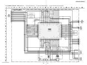
...for Waveforms. • See page 46 for IC Block Diagrams. • See page 53 for IC Pin Function Description. SCHEMATIC DIAGRAM - HCD-HX3/HX5/HX7 (Page 43) CN302 17P USB/BT LED LED STANDBY EVER+3.3V SIRCS DGND VOLUME JOG KEY0 KEY1 KEY2 FL RESET FL SD FL CS FL SCLK FL PWR ON FL... R366 R461 0 4.7k SYSTEM CONTROLLER IC301 M3062LFGPFP-710(HX3/HX5) M3062LFGPFP-712(HX7) R351 100 R451 10k C362 0.1 CDM CLOSE SW CDM OPEN SW CDM LOAD IN CDM LOAD OUT S-MASTER PG MUTE PULL UP S-MASTER RST S-MASTER SD S-MASTER DATA S-MASTER SHIFT PULL DOWN S-MASTER NSP MUTE S-MASTER INIT USB_RTS USB_CTS USB RXD/ ...
...for Waveforms. • See page 46 for IC Block Diagrams. • See page 53 for IC Pin Function Description. SCHEMATIC DIAGRAM - HCD-HX3/HX5/HX7 (Page 43) CN302 17P USB/BT LED LED STANDBY EVER+3.3V SIRCS DGND VOLUME JOG KEY0 KEY1 KEY2 FL RESET FL SD FL CS FL SCLK FL PWR ON FL... R366 R461 0 4.7k SYSTEM CONTROLLER IC301 M3062LFGPFP-710(HX3/HX5) M3062LFGPFP-712(HX7) R351 100 R451 10k C362 0.1 CDM CLOSE SW CDM OPEN SW CDM LOAD IN CDM LOAD OUT S-MASTER PG MUTE PULL UP S-MASTER RST S-MASTER SD S-MASTER DATA S-MASTER SHIFT PULL DOWN S-MASTER NSP MUTE S-MASTER INIT USB_RTS USB_CTS USB RXD/ ...

Service Manual
Page 43
... TUNE - SCHEMATIC DIAGRAM - R967 22k S967 ENTER R966 10k S966 R965 4.7k S965 + TUNE + R963 2.2k S963 R961 2.2k S962 PLAY MODE/ TUNING MODE DSGX R960 1k S961 DISPLAY CN907 3P KEY1 DGND KEY2-1 S976 R978 47k S975 R977 22k SEARCH /CANCEL R975 4.7k(HX5/HX7) 10k(HX3) R974 2.2k(HX5/HX7) 4.7k(HX3) S974 (HX3/HX7) FUNCTION AUDIO IN (HX5) S973 AUDIO IN TUNER/BAND...
... TUNE - SCHEMATIC DIAGRAM - R967 22k S967 ENTER R966 10k S966 R965 4.7k S965 + TUNE + R963 2.2k S963 R961 2.2k S962 PLAY MODE/ TUNING MODE DSGX R960 1k S961 DISPLAY CN907 3P KEY1 DGND KEY2-1 S976 R978 47k S975 R977 22k SEARCH /CANCEL R975 4.7k(HX5/HX7) 10k(HX3) R974 2.2k(HX5/HX7) 4.7k(HX3) S974 (HX3/HX7) FUNCTION AUDIO IN (HX5) S973 AUDIO IN TUNER/BAND...

Service Manual
Page 54
... 54 Power supply terminal (+3.3 V) O Subcode block sync signal output to the system controller O Not used O Not used O Not used O Zero detection signal output terminal Not used I Not used I Microcomputer interface mode selection signal input terminal Fixed at "L" I Interrupt request signal input terminal Not used O Request signal output to the USB controller (HX3/HX5) O Audio data output terminal Not used O Request signal output to the system controller and USB controller (HX3/HX5) Request signal output to the system controller (HX7) O Not used I RF signal amplitude adjustment...
... 54 Power supply terminal (+3.3 V) O Subcode block sync signal output to the system controller O Not used O Not used O Not used O Zero detection signal output terminal Not used I Not used I Microcomputer interface mode selection signal input terminal Fixed at "L" I Interrupt request signal input terminal Not used O Request signal output to the USB controller (HX3/HX5) O Audio data output terminal Not used O Request signal output to the system controller and USB controller (HX3/HX5) Request signal output to the system controller (HX7) O Not used I RF signal amplitude adjustment...

Service Manual
Page 58
... data output to the D/A converter 42 VSS - Ground terminal 30 TEST - Ground terminal 45 SAII_CLK - Not used 16 VSS - Power supply terminal (+3.3V) 5 SC_RX_IN I Serial data input from the system controller "L": reset 12 SLAVE_SEL I Command mode selection signal input terminal Not used 2 VSS - Not used 31 VSS - Not used 14 COMM_TX_DIG - Not used 8 VDD - Ground terminal 7 CDM_SEL I Master/slave mode selection signal input terminal "L": master mode, "H": slave mode Fixed at "L" in this set 13 COMM_RX_DIG...
... data output to the D/A converter 42 VSS - Ground terminal 30 TEST - Ground terminal 45 SAII_CLK - Not used 16 VSS - Power supply terminal (+3.3V) 5 SC_RX_IN I Serial data input from the system controller "L": reset 12 SLAVE_SEL I Command mode selection signal input terminal Not used 2 VSS - Not used 31 VSS - Not used 14 COMM_TX_DIG - Not used 8 VDD - Ground terminal 7 CDM_SEL I Master/slave mode selection signal input terminal "L": master mode, "H": slave mode Fixed at "L" in this set 13 COMM_RX_DIG...

Service Manual
Page 60
... USB_CTS I 38 USB_RTS O 39 S-MASTER INIT O 40 S-MASTER NSP MUTE O 41 PULL DOWN O Description Serial data output to the CD-MP3 processor SIRCS signal input from the remote control receiver Data selection signal output terminal Not used Data selection signal output terminal (HX3/HX5) Soft muting control signal output to the stream processor External data bus width selection signal input terminal Processor mode switch input terminal (for USB section "H": power on (HX3/HX5) Two-way...
... USB_CTS I 38 USB_RTS O 39 S-MASTER INIT O 40 S-MASTER NSP MUTE O 41 PULL DOWN O Description Serial data output to the CD-MP3 processor SIRCS signal input from the remote control receiver Data selection signal output terminal Not used Data selection signal output terminal (HX3/HX5) Soft muting control signal output to the stream processor External data bus width selection signal input terminal Processor mode switch input terminal (for USB section "H": power on (HX3/HX5) Two-way...

Service Manual
Page 61
... volume Input selection control signal output terminal (HX7) Input selection control signal output terminal (HX7) Input selection control signal output terminal (HX7) Transmission/reception mode notification signal output to the bluetooth module (HX5/HX7) Clear to send signal input from the bluetooth module (HX5/HX7) Power supply terminal (+3.3V) Reset signal output to the bluetooth module "L": reset (HX5/HX7) Ground terminal Power on/off control signal output terminal for bluetooth section "H": power on (HX5/HX7) Setting terminal for the model Setting terminal for the destination Plug...
... volume Input selection control signal output terminal (HX7) Input selection control signal output terminal (HX7) Input selection control signal output terminal (HX7) Transmission/reception mode notification signal output to the bluetooth module (HX5/HX7) Clear to send signal input from the bluetooth module (HX5/HX7) Power supply terminal (+3.3V) Reset signal output to the bluetooth module "L": reset (HX5/HX7) Ground terminal Power on/off control signal output terminal for bluetooth section "H": power on (HX5/HX7) Setting terminal for the model Setting terminal for the destination Plug...

Service Manual
Page 63
... the external capacitor for determines intermittent operation period when abnormal detection state I Over current detection signal and didt protection signal input terminal O Power supply output terminal for driver - Not used O Power supply output terminal for high voltage side driver I Connected to the external resistor for control circuit "L": stop I Connected to VC1 63 HCD-HX3/HX5/HX7 SWITCHING POWER BOARD IC11 CXD9841P (POWER CONTROL) Pin No. 1 2 3 4 5 6 7 8 9 10 11 12 13 14 15...
... the external capacitor for determines intermittent operation period when abnormal detection state I Over current detection signal and didt protection signal input terminal O Power supply output terminal for driver - Not used O Power supply output terminal for high voltage side driver I Connected to the external resistor for control circuit "L": stop I Connected to VC1 63 HCD-HX3/HX5/HX7 SWITCHING POWER BOARD IC11 CXD9841P (POWER CONTROL) Pin No. 1 2 3 4 5 6 7 8 9 10 11 12 13 14 15...
Service Manual
Page 66
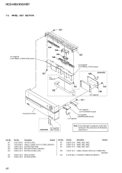
.../HX5/HX7 7-3. PANEL KEY SECTION 101 not supplied (TOP PANEL (FUNCTION) board 103 104 105 106 101 not supplied 102 107 not supplied (TOP PANEL (PLAY) board 108 (HX5/HX7) 101 101 101 109 not supplied front panel section not supplied (HX5/HX7) (ANT board) not supplied (H/P SUPPORT board) not supplied (HEADPHONE board) not supplied Note: If wire (flat type) is replaced, install...
.../HX5/HX7 7-3. PANEL KEY SECTION 101 not supplied (TOP PANEL (FUNCTION) board 103 104 105 106 101 not supplied 102 107 not supplied (TOP PANEL (PLAY) board 108 (HX5/HX7) 101 101 101 109 not supplied front panel section not supplied (HX5/HX7) (ANT board) not supplied (H/P SUPPORT board) not supplied (HEADPHONE board) not supplied Note: If wire (flat type) is replaced, install...


