
Service Manual
Page 1
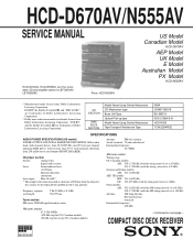
... Antenna External Antenna terminals Intermediate frequency 450 kHz - Continued on the Optical Pick-up type Model Name Using Similar Mechanism Tape Transport Mechanism Type NEW CDM37-5BD19 BU-5BD19 KSS-213BA/S-N HCD-N350 TCM-220WR2E SPECIFICATIONS AUDIO POWER SPECIFICATIONS (US model) POWER OUTPUT AND TOTAL HARMONIC DISTORTION: With 6 ohm loads, both channels driven, from 250 milliwatts to rated output (FRONT SPEAKER). Photo: HCD-N555AV US Model Canadian Model HCD-D670AV AEP Model UK Model E Model Australian Model PX Model HCD...
... Antenna External Antenna terminals Intermediate frequency 450 kHz - Continued on the Optical Pick-up type Model Name Using Similar Mechanism Tape Transport Mechanism Type NEW CDM37-5BD19 BU-5BD19 KSS-213BA/S-N HCD-N350 TCM-220WR2E SPECIFICATIONS AUDIO POWER SPECIFICATIONS (US model) POWER OUTPUT AND TOTAL HARMONIC DISTORTION: With 6 ohm loads, both channels driven, from 250 milliwatts to rated output (FRONT SPEAKER). Photo: HCD-N555AV US Model Canadian Model HCD-D670AV AEP Model UK Model E Model Australian Model PX Model HCD...
Service Manual
Page 2
..., 10% THD) SURROUND SPEAKER REAR: 35 W + 35 W(16 ohms at 1 kHz, 10% THD) Other models: Peak music power output: 1,400 W (6 Ω at 1 kHz, 10% THD) Continuous RMS power output: FRONT SPEAKER 45 W + 45 W (6 ohms, at 1 kHz, 5% THD) SUPER WOOFER 45 W + 45 W (6 ohms, 5% THD) SURROUND CENTER SPEAKER 40 W (8 ohms, at 1kHz 5% THD) SURROUND REAR SPEAKER 20 W + 20 W (16 ohms, at 1 kHz, 5% THD) Inputs PHONO (phono jack): Sensitivity 3 mV, impedance 47 kilohms VIDEO (AUDIO) (phono jack): Sensitivity 250 mV, impedance 47 kilohms MIC (phone jack): (E, Australian...
..., 10% THD) SURROUND SPEAKER REAR: 35 W + 35 W(16 ohms at 1 kHz, 10% THD) Other models: Peak music power output: 1,400 W (6 Ω at 1 kHz, 10% THD) Continuous RMS power output: FRONT SPEAKER 45 W + 45 W (6 ohms, at 1 kHz, 5% THD) SUPER WOOFER 45 W + 45 W (6 ohms, 5% THD) SURROUND CENTER SPEAKER 40 W (8 ohms, at 1kHz 5% THD) SURROUND REAR SPEAKER 20 W + 20 W (16 ohms, at 1 kHz, 5% THD) Inputs PHONO (phono jack): Sensitivity 3 mV, impedance 47 kilohms VIDEO (AUDIO) (phono jack): Sensitivity 250 mV, impedance 47 kilohms MIC (phone jack): (E, Australian...
Service Manual
Page 3
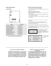
... both products are completely the same. REPLACE THESE COMPONENTS WITH SONY PARTS WHOSE PART NUMBERS APPEAR AS SHOWN IN THIS MANUAL OR IN SUPPLEMENTS PUBLISHED BY SONY. LES COMPOSANTS IDENTIFIÉS PAR UNE MARQUE ! MODEL D670AV: US model D670AV: Canadian model N555AV: AEP model N555AV: German model N555AV: Italian model N555AV: UK model N555AV: E model N555AV: Argentine model N555AV: Australian model N555AV: PX model N555AV: Mexican model PARTS No. 4-978-193-0π 4-978...
... both products are completely the same. REPLACE THESE COMPONENTS WITH SONY PARTS WHOSE PART NUMBERS APPEAR AS SHOWN IN THIS MANUAL OR IN SUPPLEMENTS PUBLISHED BY SONY. LES COMPOSANTS IDENTIFIÉS PAR UNE MARQUE ! MODEL D670AV: US model D670AV: Canadian model N555AV: AEP model N555AV: German model N555AV: Italian model N555AV: UK model N555AV: E model N555AV: Argentine model N555AV: Australian model N555AV: PX model N555AV: Mexican model PARTS No. 4-978-193-0π 4-978...
Service Manual
Page 4
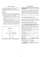
... exit form the test mode, press the TUNER/BAND , DISPLAY/ DEMO , FILE 2 buttons simultaneously again. [Switching the channel step 9 KHz/10 KHz] Press ENTER/NEXT button and POWER button simultaneously to check AC leakage. A commercial leakage tester, such as described below. The Data Precision 245 digital multimeter is 0.75 V, so analog meters must not exceed 0.5 mA (500 microampers). A) To Exposed Metal Parts on clothing...
... exit form the test mode, press the TUNER/BAND , DISPLAY/ DEMO , FILE 2 buttons simultaneously again. [Switching the channel step 9 KHz/10 KHz] Press ENTER/NEXT button and POWER button simultaneously to check AC leakage. A commercial leakage tester, such as described below. The Data Precision 245 digital multimeter is 0.75 V, so analog meters must not exceed 0.5 mA (500 microampers). A) To Exposed Metal Parts on clothing...
Service Manual
Page 5
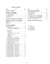
...; IC701 Master Control (TMP87CS64YF 19 5-3. Panel Section 64 5-17. TC Mechanism Section 3 (TCM-220WR2E 91 6-8. Base Unit Section (BU-5BD19 93 SECTION 7. MECHANICAL ADJUSTMENTS ......... 11 SECTION 4. Tuner Section - (AEP, UK, G, IT Model 38 5-7. Schematic Diagram - Schematic Diagram - Printed Wiring Board - Printed Wiring Board - CD Mechanism Section(CDM37-5BD19 92 6-9. Deck Section 49 5-13. Printed Wiring Board - Chassis Section 88 6-5. Disc Table 10 SECTION 3. Schematic Diagram - Tuner Section - (US...
...; IC701 Master Control (TMP87CS64YF 19 5-3. Panel Section 64 5-17. TC Mechanism Section 3 (TCM-220WR2E 91 6-8. Base Unit Section (BU-5BD19 93 SECTION 7. MECHANICAL ADJUSTMENTS ......... 11 SECTION 4. Tuner Section - (AEP, UK, G, IT Model 38 5-7. Schematic Diagram - Schematic Diagram - Printed Wiring Board - Printed Wiring Board - CD Mechanism Section(CDM37-5BD19 92 6-9. Deck Section 49 5-13. Printed Wiring Board - Chassis Section 88 6-5. Disc Table 10 SECTION 3. Schematic Diagram - Tuner Section - (US...
Service Manual
Page 11
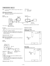
... not use a magnetized screwdriver for both decks. The adjustments should be performed with a head damagnetizer. 2. The adjustments should be performed in the order given in this adjustments for the adjustments. 4. Mode : Playback (FWD) test tape P-4-A100 (10kHz, -10dB) main board CN403 Pin 3 (L-CH) Pin 1 (R-CH) level meter set as follows unless otherwise specified. Demagnetize the record/playback head with the rated power...
... not use a magnetized screwdriver for both decks. The adjustments should be performed with a head damagnetizer. 2. The adjustments should be performed in the order given in this adjustments for the adjustments. 4. Mode : Playback (FWD) test tape P-4-A100 (10kHz, -10dB) main board CN403 Pin 3 (L-CH) Pin 1 (R-CH) level meter set as follows unless otherwise specified. Demagnetize the record/playback head with the rated power...
Service Manual
Page 12
... adjustment level. Method : 1. Frequency difference between the channels : within 1 dB of oscilloscope in playback (REV) mode. 5. Press the DISPLAY/DEMO button, MENU 1 button and TUNER/ BAND button simulateously. Adjustment Location : MD board Playback Level Adjustment DECK A DECK B Procedure : Mode : Playback (FWD) test tape P-4-L300 (315Hz, 0dB) level meter set the NORMAL SPEED mode. 5. Then at HIGH SPEED mode. 3. Press the HIGH SPEED DUBBING button again to the playback mode. 6. Turn the power switch on the MD board so that outputs...
... adjustment level. Method : 1. Frequency difference between the channels : within 1 dB of oscilloscope in playback (REV) mode. 5. Press the DISPLAY/DEMO button, MENU 1 button and TUNER/ BAND button simulateously. Adjustment Location : MD board Playback Level Adjustment DECK A DECK B Procedure : Mode : Playback (FWD) test tape P-4-L300 (315Hz, 0dB) level meter set the NORMAL SPEED mode. 5. Then at HIGH SPEED mode. 3. Press the HIGH SPEED DUBBING button again to the playback mode. 6. Turn the power switch on the MD board so that outputs...

Service Manual
Page 13
... PB LEVEL - DECK B - Mode : record DECK B AF OSC attenuator VIDEO IN 315Hz, 50mV (-23.8dB) 600Ω blank tape CS-123 set 2. If these levels do not adjustment level, adjust the RV301 (L-CH) and RV351 (R-CH) on the MD board to -23.3 dB) Adjustment Location : main board Adjustment Location [MAIN BOARD] (Component Side) 1 3 CN403 RV351 REC LEVEL (R-CH) RV301 REC LEVEL (L-CH) Record Level Adjustment Procedure : 1. Adjustment level : The playback output...
... PB LEVEL - DECK B - Mode : record DECK B AF OSC attenuator VIDEO IN 315Hz, 50mV (-23.8dB) 600Ω blank tape CS-123 set 2. If these levels do not adjustment level, adjust the RV301 (L-CH) and RV351 (R-CH) on the MD board to -23.3 dB) Adjustment Location : main board Adjustment Location [MAIN BOARD] (Component Side) 1 3 CN403 RV351 REC LEVEL (R-CH) RV301 REC LEVEL (L-CH) Record Level Adjustment Procedure : 1. Adjustment level : The playback output...
Service Manual
Page 14
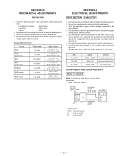
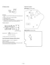
... Tuned Level Adjustment Note : FM Tuned Level adjustment should be performed after the AM Tuned FM Tuned Level Level Adjustement. Procedure : 1. Tune the set Carrier frequency : 98MHz Modulation : AUDIO 1kHz, 75kHz deviation (100%) Output level : 25dB (at 10 kHz step) 60 cm AM antenna terminal (TM1) Field strength dB (µV/m)=SGG output level dB (µV/m)-26dB. Adjust RV42 (AEP, UK, IT, G models), RV41 (other models) to the point (moment) when the TUNED indicator will change...
... Tuned Level Adjustment Note : FM Tuned Level adjustment should be performed after the AM Tuned FM Tuned Level Level Adjustement. Procedure : 1. Tune the set Carrier frequency : 98MHz Modulation : AUDIO 1kHz, 75kHz deviation (100%) Output level : 25dB (at 10 kHz step) 60 cm AM antenna terminal (TM1) Field strength dB (µV/m)=SGG output level dB (µV/m)-26dB. Adjust RV42 (AEP, UK, IT, G models), RV41 (other models) to the point (moment) when the TUNED indicator will change...

Service Manual
Page 15
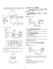
... TP(RF) TP(VC) oscilloscope (DC range) Procedure : 1. Turned Power switch on . 4. Put disc (YEDS-18) in and playback. 4. Turn Power switch on . 3. Connect oscilloscope to test point TP (FEO). 2. RF signal waveform VOLT/DIV : 200mV TIME/DIV : 500nS level : 1.3 ± 0.3 Vp-p - 15 - Use YEDS-18 disc (3-702-101-01) unless otherwise indicated. 3. Clean the object lens by lead wire. 3. Adjust RV101 so that the shape "◊...
... TP(RF) TP(VC) oscilloscope (DC range) Procedure : 1. Turned Power switch on . 4. Put disc (YEDS-18) in and playback. 4. Turn Power switch on . 3. Connect oscilloscope to test point TP (FEO). 2. RF signal waveform VOLT/DIV : 200mV TIME/DIV : 500nS level : 1.3 ± 0.3 Vp-p - 15 - Use YEDS-18 disc (3-702-101-01) unless otherwise indicated. 3. Clean the object lens by lead wire. 3. Adjust RV101 so that the shape "◊...
Service Manual
Page 16
... the top and bottom in relation to test point TP (TEO). 3. Put disc (YEDS-18) in step 1. E-F Balance Check BD board TP (TEO) TP (VC) oscilloscope Procedure : 1. Remove the lead wire connected in and playback. 5. Adjustment Location : [BD BOARD] (Conductor Side...Turned Power switch on Main board to mechanical center position when you moved and do not perform this level. There is slightly off. Connect test point TP (ADJ) on . 4. Focus/Tracking Gain Adjustment (RV102, RV103) This gain has a margin, so even if it should be fixed to Ground with a lead wire. 2. Connect...
... the top and bottom in relation to test point TP (TEO). 3. Put disc (YEDS-18) in step 1. E-F Balance Check BD board TP (TEO) TP (VC) oscilloscope Procedure : 1. Remove the lead wire connected in and playback. 5. Adjustment Location : [BD BOARD] (Conductor Side...Turned Power switch on Main board to mechanical center position when you moved and do not perform this level. There is slightly off. Connect test point TP (ADJ) on . 4. Focus/Tracking Gain Adjustment (RV102, RV103) This gain has a margin, so even if it should be fixed to Ground with a lead wire. 2. Connect...
Service Manual
Page 18
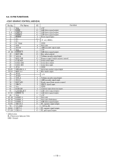
... - +5V O LED drive signal output. I Volume encoder signal input. O FL segment signal output. - -25V for FL O FL segment signal output. 5-2. O LED drive signal output. - +5V O Not used . (Pull down) O LED drive signal output. O FL grid signal output. - 18 - O Key select control. I Key matrix input. - - +5V I Volume encoder signal input. O LED drive signal output. GND I AMS encoder signal input. I Spectram analizer signal input. O LED drive signal output. GND I SIRCS signal input. - O Request signal from master control. I CD door open...
... - +5V O LED drive signal output. I Volume encoder signal input. O FL segment signal output. - -25V for FL O FL segment signal output. 5-2. O LED drive signal output. - +5V O Not used . (Pull down) O LED drive signal output. O FL grid signal output. - 18 - O Key select control. I Key matrix input. - - +5V I Volume encoder signal input. O LED drive signal output. GND I AMS encoder signal input. I Spectram analizer signal input. O LED drive signal output. GND I SIRCS signal input. - O Request signal from master control. I CD door open...
Service Manual
Page 19
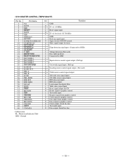
... switch signal input. (Pull up) O O Loading motor control signal output. (Not used ). I Connected to GND I I Input selector control signal output. (Pull up) I I Disc table up signal input. I X' tal (10 MHz). O Ready signal to graphic control. GND O I Sub-code sync signal input. I RDS data start input. O Super woofer ON/OFF control. I Reset signal input. O Clock output. O Data output. I Request signal from graphic control. I RDS data output. I Test mode input. I Data input from graphic control. O Reset signal output for tuner...
... switch signal input. (Pull up) O O Loading motor control signal output. (Not used ). I Connected to GND I I Input selector control signal output. (Pull up) I I Disc table up signal input. I X' tal (10 MHz). O Ready signal to graphic control. GND O I Sub-code sync signal input. I RDS data start input. O Super woofer ON/OFF control. I Reset signal input. O Clock output. O Data output. I Request signal from graphic control. I RDS data output. I Test mode input. I Data input from graphic control. O Reset signal output for tuner...
Service Manual
Page 20
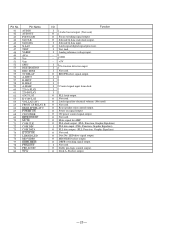
... VDD SPEC DESTINATION DISC SENS TC RELAY A-SHUT B-SHUT B-HALF A-HALF 220-A-PLAY 220-B-PLAY 62427 LAT K-CON-LAT VOL LAT (AV) FRONT SP RELAY B REAR SP RELAY C POWER ON CD POWER RPOLOG LAT MUTE COM CLK COM DIN COM DATA K CON ON LIDDED LED MD/VIDEO DBFB-HIGH PWM-OUT PRO-LOGIC TC A I/O Function I O Audio bus in/output. (Not used . O Latch signal digital signal processor. I Control signal input form deck. GND...
... VDD SPEC DESTINATION DISC SENS TC RELAY A-SHUT B-SHUT B-HALF A-HALF 220-A-PLAY 220-B-PLAY 62427 LAT K-CON-LAT VOL LAT (AV) FRONT SP RELAY B REAR SP RELAY C POWER ON CD POWER RPOLOG LAT MUTE COM CLK COM DIN COM DATA K CON ON LIDDED LED MD/VIDEO DBFB-HIGH PWM-OUT PRO-LOGIC TC A I/O Function I O Audio bus in/output. (Not used . O Latch signal digital signal processor. I Control signal input form deck. GND...
Service Manual
Page 21
... signal output. O REC/PB control signal output. O Trigger motor high/low control signal output. O Latch signal output for deck. O Mute output. O Mute signal output for tuner. O ECHO delay ON/OFF control signal output (Not used) O O ECHO delay level control signal output (Not used . M-HIGH A-TRG B-TRG TRG LOW CAP M ON STEREO TUNED ST-CE DELAY SEL MIC DELAY ON DELAY LEVEL A DELAY LEVEL B VDD I Stereo detection signal from tuner. O Dolby switching signal output. I Tuned detection signal from tuner. O Capstan motor control signal output. O Bias oscillation output...
... signal output. O REC/PB control signal output. O Trigger motor high/low control signal output. O Latch signal output for deck. O Mute output. O Mute signal output for tuner. O ECHO delay ON/OFF control signal output (Not used) O O ECHO delay level control signal output (Not used . M-HIGH A-TRG B-TRG TRG LOW CAP M ON STEREO TUNED ST-CE DELAY SEL MIC DELAY ON DELAY LEVEL A DELAY LEVEL B VDD I Stereo detection signal from tuner. O Dolby switching signal output. I Tuned detection signal from tuner. O Capstan motor control signal output. O Bias oscillation output...
Service Manual
Page 43
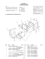
...-011-11 WIRE (FLAT TYPE)(15 CORE)(N555AV:AEP,UK) * 8 4-956-370-12 BAND, PLUG FIXED (N555AV:UK,AUS *8 3-363-099-01 SCREW (CASE 3 TP2) *8 Part No. Description Remark Ref. Some delay should be anticipated when ordering these items. • The mechanical parts with no reference number in the exploded views are critical for routine service. are not...
...-011-11 WIRE (FLAT TYPE)(15 CORE)(N555AV:AEP,UK) * 8 4-956-370-12 BAND, PLUG FIXED (N555AV:UK,AUS *8 3-363-099-01 SCREW (CASE 3 TP2) *8 Part No. Description Remark Ref. Some delay should be anticipated when ordering these items. • The mechanical parts with no reference number in the exploded views are critical for routine service. are not...
Service Manual
Page 45
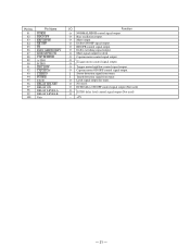
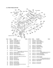
...978-124-11 BUTTON (DOLBY) (D670AV/N555AV:E,AUS,PX,MX,AR) 133 4-978-120-01 BUTTON (TUNING) 110 4-978-131-11 DISPLAY (ST)(N555AV:AEP,UK,G,IT) (D670AV/N555AV:E,AUS,PX,MX,AR) 111 4-978-146-01 BUTTON (EJECT-L) 133 4-978-120-11 BUTTON (TUNING)(N555AV:AEP,UK,G,IT) 112 4-978-116-01 PANEL, FRONT (D670AV) 134 4-... BUTTON (PLAY) - 87 - Description 4-951-620-01 SCREW (2.6X8), +BVTP 1-659-405-11 CD JOG BOARD 4-978-153-01 BUTTON (PROGRAM) 4-978-712-01 BUTTON (SHUFFLE) 4-978-155-01 PLATE, ORNAMENTAL 138 101 121 139 136 140 141 136 101 122 105 103 102 101 Remark Ref. Part No. FRONT PANEL ...
...978-124-11 BUTTON (DOLBY) (D670AV/N555AV:E,AUS,PX,MX,AR) 133 4-978-120-01 BUTTON (TUNING) 110 4-978-131-11 DISPLAY (ST)(N555AV:AEP,UK,G,IT) (D670AV/N555AV:E,AUS,PX,MX,AR) 111 4-978-146-01 BUTTON (EJECT-L) 133 4-978-120-11 BUTTON (TUNING)(N555AV:AEP,UK,G,IT) 112 4-978-116-01 PANEL, FRONT (D670AV) 134 4-... BUTTON (PLAY) - 87 - Description 4-951-620-01 SCREW (2.6X8), +BVTP 1-659-405-11 CD JOG BOARD 4-978-153-01 BUTTON (PROGRAM) 4-978-712-01 BUTTON (SHUFFLE) 4-978-155-01 PLATE, ORNAMENTAL 138 101 121 139 136 140 141 136 101 122 105 103 102 101 Remark Ref. Part No. FRONT PANEL ...
Service Manual
Page 52
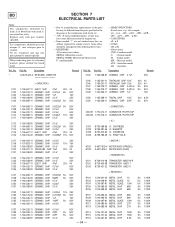
... parts by mark ! Part No. BD SECTION 7 ELECTRICAL PARTS LIST Note: The components identified by reference number, please include the board name. • Due to standardization, replacements in the parts list may have some difference from the parts specified in ohms ...delay should be different from the original one. • Items marked "*" are not stocked since they may be anticipated when ordering these items. • RESISTORS All resistors are in the diagrams or the components used on the set. • -XX, -X mean standardized parts, so they are critical for routine service...
... parts by mark ! Part No. BD SECTION 7 ELECTRICAL PARTS LIST Note: The components identified by reference number, please include the board name. • Due to standardization, replacements in the parts list may have some difference from the parts specified in ohms ...delay should be different from the original one. • Items marked "*" are not stocked since they may be anticipated when ordering these items. • RESISTORS All resistors are in the diagrams or the components used on the set. • -XX, -X mean standardized parts, so they are critical for routine service...
Service Manual
Page 66
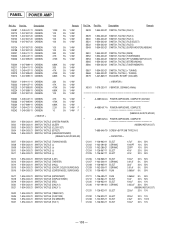
... 1-554-303-21 1-554-303-21 1-554-303-21 SWITCH, TACTILE (DBFB) SWITCH, TACTILE (TUNER/BAND) SWITCH, TACTILE (PTY)(N555AV:AEP,UK,G,IT) SWITCH, TACTILE (STEREO/MONO) SWITCH, TACTILE (TUNER MEMORY) S567 S568 S579 1-554-303-21 SWITCH, TACTILE (+ TUNING) 1-554-303-21 SWITCH, TACTILE (- PANEL POWER AMP Ref. Part No. TUNING) 1-467-869-11 ENCODER, ROTARY (VOLUME) R3221 R3222 R3223 R3224 R3231 1-249-411-11 CARBON...
... 1-554-303-21 1-554-303-21 1-554-303-21 SWITCH, TACTILE (DBFB) SWITCH, TACTILE (TUNER/BAND) SWITCH, TACTILE (PTY)(N555AV:AEP,UK,G,IT) SWITCH, TACTILE (STEREO/MONO) SWITCH, TACTILE (TUNER MEMORY) S567 S568 S579 1-554-303-21 SWITCH, TACTILE (+ TUNING) 1-554-303-21 SWITCH, TACTILE (- PANEL POWER AMP Ref. Part No. TUNING) 1-467-869-11 ENCODER, ROTARY (VOLUME) R3221 R3222 R3223 R3224 R3231 1-249-411-11 CARBON...

Service Manual
Page 78
HCD-D670AV/N555AV 9-960-525-11 Sony Corporation Consumer A&V Products Company Home A&V Products Div. - 120 - Quality Engineering Dept. English 96C0996-1 Printed in Japan © 1996. 3 Published by Home A&V Products Div.
HCD-D670AV/N555AV 9-960-525-11 Sony Corporation Consumer A&V Products Company Home A&V Products Div. - 120 - Quality Engineering Dept. English 96C0996-1 Printed in Japan © 1996. 3 Published by Home A&V Products Div.


