Operating Instructions
Page 1
To find out details on any available updates, please visit: http://www.sony.com/bluraysupport/ Printed in the future. 4-178-242-11(1) The software of this system may be updated in Malaysia (1) Blu-ray Disc/DVD Home Theatre System Operating Instructions BDV-E770W / T77 © 2010 Sony Corporation
To find out details on any available updates, please visit: http://www.sony.com/bluraysupport/ Printed in the future. 4-178-242-11(1) The software of this system may be updated in Malaysia (1) Blu-ray Disc/DVD Home Theatre System Operating Instructions BDV-E770W / T77 © 2010 Sony Corporation
Operating Instructions
Page 2
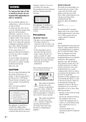
... a bookcase or built-in this Blu-ray Disc / DVD Home Theatre System is intended to alert the user...a CLASS 1 LASER product. Record the serial number in the U.S.A. BDV-E770W/BDVT77 Serial No The following FCC statement applies only to the AC outlet,...apparatus. These limits are designed to disassemble the cabinet. Reorient or relocate the receiving antenna (aerial). - This symbol is no guarantee that to persons. Other...comply with newspapers, tablecloths, curtains, etc. Should you call upon your Sony dealer regarding this product. WARNING To reduce the risk of fire or ...
... a bookcase or built-in this Blu-ray Disc / DVD Home Theatre System is intended to alert the user...a CLASS 1 LASER product. Record the serial number in the U.S.A. BDV-E770W/BDVT77 Serial No The following FCC statement applies only to the AC outlet,...apparatus. These limits are designed to disassemble the cabinet. Reorient or relocate the receiving antenna (aerial). - This symbol is no guarantee that to persons. Other...comply with newspapers, tablecloths, curtains, etc. Should you call upon your Sony dealer regarding this product. WARNING To reduce the risk of fire or ...

Operating Instructions
Page 3
...to OET65. For the USB Wireless LAN Adapter (UWABR100) Pursuant to FCC regulations, you have any questions about this product, contact Sony Customer Information Service Center at plugs, convenience receptacles, and the point where they have fallen into your outlet, consult an electrician for...or modifications not expressly approved in this manual could void your authority to operate this equipment. As an ENERGY STAR® partner, Sony Corporation has determined that this device is a U.S. Important Safety Instructions 1) Read these instructions. 2) Keep these radars could cause ...
...to OET65. For the USB Wireless LAN Adapter (UWABR100) Pursuant to FCC regulations, you have any questions about this product, contact Sony Customer Information Service Center at plugs, convenience receptacles, and the point where they have fallen into your outlet, consult an electrician for...or modifications not expressly approved in this manual could void your authority to operate this equipment. As an ENERGY STAR® partner, Sony Corporation has determined that this device is a U.S. Important Safety Instructions 1) Read these instructions. 2) Keep these radars could cause ...
Operating Instructions
Page 4
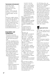
... "BD-LIVE" and "BONUSVIEW" are trademarks of Blu-ray Disc Association. • "Blu-ray Disc" is a trademark. • "Blu-ray Disc," "DVD+RW," "DVD-RW," "DVD+R," "DVDR," "DVD VIDEO," and "CD" logos are trademarks. • "BRAVIA... engineering or disassembly is subject to this copyright protection technology must accept any interference received, including interference that is the industry standard in the United States and/or other...and product names are not indicated in this device or its logo are trademarks of Sony Corporation. • , "XMB," and "xross media bar" are provided by ...
... "BD-LIVE" and "BONUSVIEW" are trademarks of Blu-ray Disc Association. • "Blu-ray Disc" is a trademark. • "Blu-ray Disc," "DVD+RW," "DVD-RW," "DVD+R," "DVDR," "DVD VIDEO," and "CD" logos are trademarks. • "BRAVIA... engineering or disassembly is subject to this copyright protection technology must accept any interference received, including interference that is the industry standard in the United States and/or other...and product names are not indicated in this device or its logo are trademarks of Sony Corporation. • , "XMB," and "xross media bar" are provided by ...
Operating Instructions
Page 5
... indicated in the text, for BDV-E770W and BDV-T77. You can also use the controls on the unit if they have the same or similar names as those on the remote. • In this manual, "disc" is used as a general reference for BDs, DVDs, Super Audio CDs, or CDs unless... depending on the area. • The default setting is underlined. • The system is used for the surround amplifier, surround back amplifier, or S-AIR receiver in these Operating Instructions describe the controls on the S-AIR function, see "Using an S-AIR Product" (page 39). • Notes or instructions for illustration...
... indicated in the text, for BDV-E770W and BDV-T77. You can also use the controls on the unit if they have the same or similar names as those on the remote. • In this manual, "disc" is used as a general reference for BDs, DVDs, Super Audio CDs, or CDs unless... depending on the area. • The default setting is underlined. • The system is used for the surround amplifier, surround back amplifier, or S-AIR receiver in these Operating Instructions describe the controls on the S-AIR function, see "Using an S-AIR Product" (page 39). • Notes or instructions for illustration...
Operating Instructions
Page 6
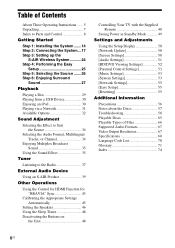
...in Standby Mode 49 Settings and Adjustments Using the Setup Display 50 [Network Update 50 [Screen Settings 50 [Audio Settings 51 [BD/DVD Viewing Settings 52 [Parental Control Settings 53 [Music Settings 53 [System Settings 53 [Network Settings 55 [Easy Setup 55 [Resetting 55... Additional Information Precautions 56 Notes about the Discs 57 Troubleshooting 58 Playable Discs 65 Playable Types of Files 66 Supported Audio Formats 67 Video Output Resolution 67 Specifications 68 Language Code List 70 Glossary...
...in Standby Mode 49 Settings and Adjustments Using the Setup Display 50 [Network Update 50 [Screen Settings 50 [Audio Settings 51 [BD/DVD Viewing Settings 52 [Parental Control Settings 53 [Music Settings 53 [System Settings 53 [Network Settings 55 [Easy Setup 55 [Resetting 55... Additional Information Precautions 56 Notes about the Discs 57 Troubleshooting 58 Playable Discs 65 Playable Types of Files 66 Supported Audio Formats 67 Video Output Resolution 67 Specifications 68 Language Code List 70 Glossary...
Operating Instructions
Page 7
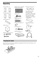
... cord (1) • Remote commander (remote) (1) • Operating Instructions • Quick Setup Guide • To stabilize S-AIR reception • End user license agreement • Easy Setup Disc (DVD) • USB Wireless LAN Adapter (UWA-BR100) • R6 (size AA) batteries (2) • UWA-BR100 External cable • Calibration mic (1) • Surround amplifier (1) • FM...
... cord (1) • Remote commander (remote) (1) • Operating Instructions • Quick Setup Guide • To stabilize S-AIR reception • End user license agreement • Easy Setup Disc (DVD) • USB Wireless LAN Adapter (UWA-BR100) • R6 (size AA) batteries (2) • UWA-BR100 External cable • Calibration mic (1) • Surround amplifier (1) • FM...

Operating Instructions
Page 8
...FUNCTION VOLUME VOLUME A "/1 (on/standby) Turns on . N (play) Starts or re-starts playback (resume play). Plays a slideshow when a disc containing JPEG image files is turned on the unit, or sets it to the pages indicated in parentheses. D Front panel display E (remote sensor) ...F Power indicator Lights up while the system is inserted. B Play operation buttons Z (open/close) (page 29) Opens or closes the disc tray. The resume point for a title/track is the last point you played or the last photo for connecting a USB device. x (stop) Stops playback ...
...FUNCTION VOLUME VOLUME A "/1 (on/standby) Turns on . N (play) Starts or re-starts playback (resume play). Plays a slideshow when a disc containing JPEG image files is turned on the unit, or sets it to the pages indicated in parentheses. D Front panel display E (remote sensor) ...F Power indicator Lights up while the system is inserted. B Play operation buttons Z (open/close) (page 29) Opens or closes the disc tray. The resume point for a title/track is the last point you played or the last photo for connecting a USB device. x (stop) Stops playback ...

Operating Instructions
Page 9
...up when muting is on. 9US L Lights up when repeat play is activated. E Lights up when a station is received. (Radio only) (page 37) F Lights up when stereo sound is received. (Radio only) (page 37) G Flashes when the sleep timer is set to an HDCP (Highbandwidth Digital Content Protection...signals from the COMPONENT VIDEO OUT jacks. Front panel display About the indications in standby mode while wireless transmission between the unit and S-AIR receiver is not activated. (page 39) I Displays system's status such as chapter, title, or track number, time information, radio frequency, playing ...
...up when muting is on. 9US L Lights up when repeat play is activated. E Lights up when a station is received. (Radio only) (page 37) F Lights up when stereo sound is received. (Radio only) (page 37) G Flashes when the sleep timer is set to an HDCP (Highbandwidth Digital Content Protection...signals from the COMPONENT VIDEO OUT jacks. Front panel display About the indications in standby mode while wireless transmission between the unit and S-AIR receiver is not activated. (page 39) I Displays system's status such as chapter, title, or track number, time information, radio frequency, playing ...

Operating Instructions
Page 10
CAL MIC ECM-AC2 S-AIR ID ABC EZW-RT10 AUDIO R AUDIO IN L A (USB) port (page 30) B LAN (100) terminal (page 23) C COMPONENT VIDEO OUT jacks (page 18) D VIDEO OUT jack (page 18) E HDMI OUT jack (page 18) F EZW-RT10 slot (page 22) G AUDIO (AUDIO IN L/R) jacks (page 20) H S-AIR ID switch (pages 24, 39) I A.CAL MIC jack (pages 25, 45) J ANTENNA (FM COAXIAL 75Ω) jack (page 21) K TV (DIGITAL IN OPTICAL) jack (page 19) L SAT/CABLE (DIGITAL IN COAXIAL) jack (page 20) M SPEAKERS jacks (page 17) 10US Rear panel SPEAKERS FRONT R FRONT L SUBWOOFER CENTER LAN(100) VIDEO OUT Y PB / CB ...
CAL MIC ECM-AC2 S-AIR ID ABC EZW-RT10 AUDIO R AUDIO IN L A (USB) port (page 30) B LAN (100) terminal (page 23) C COMPONENT VIDEO OUT jacks (page 18) D VIDEO OUT jack (page 18) E HDMI OUT jack (page 18) F EZW-RT10 slot (page 22) G AUDIO (AUDIO IN L/R) jacks (page 20) H S-AIR ID switch (pages 24, 39) I A.CAL MIC jack (pages 25, 45) J ANTENNA (FM COAXIAL 75Ω) jack (page 21) K TV (DIGITAL IN OPTICAL) jack (page 19) L SAT/CABLE (DIGITAL IN COAXIAL) jack (page 20) M SPEAKERS jacks (page 17) 10US Rear panel SPEAKERS FRONT R FRONT L SUBWOOFER CENTER LAN(100) VIDEO OUT Y PB / CB ...

Operating Instructions
Page 11
Flashes orange. G SPEAKERS jacks H Wireless transceiver (EZW-RT10) slot 11US Flashes red. C S-AIR ID switch Selects the S-AIR ID. Flashes green slowly. The surround amplifier is in standby mode while the system is in standby mode or wireless transmission is deactivated. D PAIRING button Starts pairing. E PAIRING indicator Indicates the pairing status. The system is turned on , wireless transmission is activated and surround signals are not transmitting. The wireless transceiver is active. B S-AIR/STANDBY indicator You can check the status of wireless ...
Flashes orange. G SPEAKERS jacks H Wireless transceiver (EZW-RT10) slot 11US Flashes red. C S-AIR ID switch Selects the S-AIR ID. Flashes green slowly. The surround amplifier is in standby mode while the system is in standby mode or wireless transmission is deactivated. D PAIRING button Starts pairing. E PAIRING indicator Indicates the pairing status. The system is turned on , wireless transmission is activated and surround signals are not transmitting. The wireless transceiver is active. B S-AIR/STANDBY indicator You can check the status of wireless ...

Operating Instructions
Page 12
... or sets it to a displayed item. (ENTER) Enters the selected item. POP UP/MENU Opens or closes the BD-ROM's Pop-up Menu, or the DVD's menu. C/X/x/c Moves the highlight to standby mode. B Number buttons (pages 38, 48) Enters the title/chapter numbers, radio frequencies, etc. ONE-TOUCH PLAY (...watching movies automatically. C Color buttons (YELLOW/BLUE/RED/ GREEN) Short cut keys for selecting items on BDs). D TOP MENU Opens or closes the BD's or DVD's Top Menu. HOME (pages 25, 37, 39, 45, 46, 50) Enters or exits the system's home menu. SOUND MODE (page 34) Selects the sound...
... or sets it to a displayed item. (ENTER) Enters the selected item. POP UP/MENU Opens or closes the BD-ROM's Pop-up Menu, or the DVD's menu. C/X/x/c Moves the highlight to standby mode. B Number buttons (pages 38, 48) Enters the title/chapter numbers, radio frequencies, etc. ONE-TOUCH PLAY (...watching movies automatically. C Color buttons (YELLOW/BLUE/RED/ GREEN) Short cut keys for selecting items on BDs). D TOP MENU Opens or closes the BD's or DVD's Top Menu. HOME (pages 25, 37, 39, 45, 46, 50) Enters or exits the system's home menu. SOUND MODE (page 34) Selects the sound...

Operating Instructions
Page 13
... is inserted. F Playback operation buttons See "Playback" (page 29). ./> (previous/next) Skip to the Favorites List. Plays a slideshow when a disc containing JPEG image files is "TV" or "SAT/ CABLE" and digital signals are input via the DIGITAL IN jack, displays the stream information in... seconds. Activates slow-motion play ). G MUTING Turns off the sound temporarily. m/M (fast reverse/fast forward) Fast reverse/fast forward the disc during playback. FAVORITES Displays the Internet contents added to the previous/next chapter, track, or file. (replay/advance) Briefly replay the current ...
... is inserted. F Playback operation buttons See "Playback" (page 29). ./> (previous/next) Skip to the Favorites List. Plays a slideshow when a disc containing JPEG image files is "TV" or "SAT/ CABLE" and digital signals are input via the DIGITAL IN jack, displays the stream information in... seconds. Activates slow-motion play ). G MUTING Turns off the sound temporarily. m/M (fast reverse/fast forward) Fast reverse/fast forward the disc during playback. FAVORITES Displays the Internet contents added to the previous/next chapter, track, or file. (replay/advance) Briefly replay the current ...
Operating Instructions
Page 14
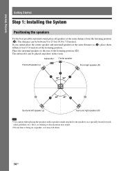
Place the surround speakers to the rear of the listening position. Subwoofer Center speaker Front left speaker (L) Front right speaker (R) A A A 30 30 B A 45 45 A B Surround left speaker (L) Surround right speaker (R) Note • Use caution when placing the speakers and/or speaker stands attached to 7.0 meters). Getting Started Getting Started Step 1: Installing the System Positioning the speakers For the best possible surround sound, place all speakers at the same distance as it may result. • Do not lean or hang on a speaker, as (A), place them within 23 feet...
Place the surround speakers to the rear of the listening position. Subwoofer Center speaker Front left speaker (L) Front right speaker (R) A A A 30 30 B A 45 45 A B Surround left speaker (L) Surround right speaker (R) Note • Use caution when placing the speakers and/or speaker stands attached to 7.0 meters). Getting Started Getting Started Step 1: Installing the System Positioning the speakers For the best possible surround sound, place all speakers at the same distance as it may result. • Do not lean or hang on a speaker, as (A), place them within 23 feet...
Operating Instructions
Page 15
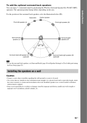
... is not responsible for the wall material and strength. The optional product lineup differs depending on a vertical and flat wall where reinforcement is applied. • Sony is especially fragile, attach the screws securely to a beam and fasten them to [Yes] while performing the Easy Setup (page 25). Install the speakers on...
... is not responsible for the wall material and strength. The optional product lineup differs depending on a vertical and flat wall where reinforcement is applied. • Sony is especially fragile, attach the screws securely to a beam and fasten them to [Yes] while performing the Easy Setup (page 25). Install the speakers on...

Operating Instructions
Page 16
See the illustrations below. 4 mm (3/16 inch) 30 mm (1 3/16 inches) 5 mm (7/32 inch) 10 mm (13/32 inch) Hole on the back of the speaker 2 Fasten the screws to 13/32 inch) 3 Hang the speakers on the screws. 5 mm (7/32 inch) 10 mm (13/32 inch) Hole on the back of the speaker 16US Rear of each speaker. Color tube Front left speaker (L): White Front right speaker (R): Red Center speaker: Green Surround left speaker (L): Blue Surround right speaker (R): Gray 1 Prepare screws (not supplied) that are suitable for the hole on the back of the speaker For the center speaker 219 mm (8 ...
See the illustrations below. 4 mm (3/16 inch) 30 mm (1 3/16 inches) 5 mm (7/32 inch) 10 mm (13/32 inch) Hole on the back of the speaker 2 Fasten the screws to 13/32 inch) 3 Hang the speakers on the screws. 5 mm (7/32 inch) 10 mm (13/32 inch) Hole on the back of the speaker 16US Rear of each speaker. Color tube Front left speaker (L): White Front right speaker (R): Red Center speaker: Green Surround left speaker (L): Blue Surround right speaker (R): Gray 1 Prepare screws (not supplied) that are suitable for the hole on the back of the speaker For the center speaker 219 mm (8 ...

Operating Instructions
Page 17
Do not connect the AC power cord (mains lead) of the unit to the unit and surround amplifier, insert the connector until all the other components to the speaker Color tube (+) Rear or bottom of the surround amplifier Gray (Surround right speaker (R)) Green (Center speaker) Purple (Subwoofer) R L IMPEDANC3E-1U6SE SPEAKERS Blue (Surround left speaker (L)) To connect speaker cords to a level where sound is not distorted. Note • When you connect another component with the color tube to 3, and the speaker cord without the color tube to match the color of the SPEAKERS jacks of...
Do not connect the AC power cord (mains lead) of the unit to the unit and surround amplifier, insert the connector until all the other components to the speaker Color tube (+) Rear or bottom of the surround amplifier Gray (Surround right speaker (R)) Green (Center speaker) Purple (Subwoofer) R L IMPEDANC3E-1U6SE SPEAKERS Blue (Surround left speaker (L)) To connect speaker cords to a level where sound is not distorted. Note • When you connect another component with the color tube to 3, and the speaker cord without the color tube to match the color of the SPEAKERS jacks of...

Operating Instructions
Page 18
To the video input jack of the TV. * The HDMI cable is supplied with an HDMI cable. When connecting with the component video cable, you need to select the type of output signal (page 51). Rear panel of the unit B Component video cable (not supplied) VIDEO OUT PR / CR CYOMPONEPNB T/ CVBIDEO OUT ARC OUT A HDMI cable* C Video cord (supplied) To the component video input jacks of the TV. Method 2: Component video cable (B) connection If your TV, select the connection method. Getting Started Connecting the TV (Video connection) This connection sends a video signal to using the ...
To the video input jack of the TV. * The HDMI cable is supplied with an HDMI cable. When connecting with the component video cable, you need to select the type of output signal (page 51). Rear panel of the unit B Component video cable (not supplied) VIDEO OUT PR / CR CYOMPONEPNB T/ CVBIDEO OUT ARC OUT A HDMI cable* C Video cord (supplied) To the component video input jacks of the TV. Method 2: Component video cable (B) connection If your TV, select the connection method. Getting Started Connecting the TV (Video connection) This connection sends a video signal to using the ...

Operating Instructions
Page 19
.... About Audio Return Channel If your TV is compatible with an audio cord, see [Audio Return Channel] (page 54). With a digital audio connection, the system receives a Dolby Digital multiplex broadcast signal and you connect the TV and the unit with the Audio Return Channel function, an HDMI cable connection also sends...
.... About Audio Return Channel If your TV is compatible with an audio cord, see [Audio Return Channel] (page 54). With a digital audio connection, the system receives a Dolby Digital multiplex broadcast signal and you connect the TV and the unit with the Audio Return Channel function, an HDMI cable connection also sends...

Operating Instructions
Page 20
To the audio out jacks of the VCR or digital satellite receiver, etc. Getting Started Connecting the other components When you connect the system and other components to the TV, video signals from the system and the ... flow : Video signal : Audio signal You can enjoy connected components via the system's speakers. • VCR or digital satellite receiver, etc. (not supplied), which has a digital coaxial output jack: D • VCR, digital satellite receiver, PlayStation, or portable audio source, etc. (not supplied): E Rear panel of the unit D Digital coaxial cord (not supplied...
To the audio out jacks of the VCR or digital satellite receiver, etc. Getting Started Connecting the other components When you connect the system and other components to the TV, video signals from the system and the ... flow : Video signal : Audio signal You can enjoy connected components via the system's speakers. • VCR or digital satellite receiver, etc. (not supplied), which has a digital coaxial output jack: D • VCR, digital satellite receiver, PlayStation, or portable audio source, etc. (not supplied): E Rear panel of the unit D Digital coaxial cord (not supplied...