Operating Instructions
Page 14
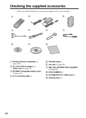
Checking the supplied accessories Make sure that the following accessories are supplied with your camcorder. 1 2 3 4 5 6 7 8 9 0 1 Wireless Remote Commander (1) (page 142) 2 AC-L15A/L15B AC adaptor (1), Power cord (1) (page 16) 3 NP-FM50 rechargeable battery pack (1) (page 15) 4 A/V connecting cable (1) 5 Shoulder strap (1) 6 Lens cap (1) (page 28) 7 USB cable (Hi-SPEED USB compatible) (1) (page 92) 8 DVD-R (DMR30) (1) 9 CD-ROM (SPVD-011 USB Driver) (1) q; Cleaning cloth (1) 14
Checking the supplied accessories Make sure that the following accessories are supplied with your camcorder. 1 2 3 4 5 6 7 8 9 0 1 Wireless Remote Commander (1) (page 142) 2 AC-L15A/L15B AC adaptor (1), Power cord (1) (page 16) 3 NP-FM50 rechargeable battery pack (1) (page 15) 4 A/V connecting cable (1) 5 Shoulder strap (1) 6 Lens cap (1) (page 28) 7 USB cable (Hi-SPEED USB compatible) (1) (page 92) 8 DVD-R (DMR30) (1) 9 CD-ROM (SPVD-011 USB Driver) (1) q; Cleaning cloth (1) 14
Operating Instructions
Page 22
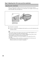
... brightness of the viewfinder backlight. When the pictures on battery consumption. 22 Adjust the viewfinder lens to see the characters in the viewfinder comes into sharp focus. 2 1 Viewfinder lens adjustment dial 1 Extend the viewfinder. 2 Turn the viewfinder lens adjustment dial until you want to save on the LCD screen are hard to accommodate...
... brightness of the viewfinder backlight. When the pictures on battery consumption. 22 Adjust the viewfinder lens to see the characters in the viewfinder comes into sharp focus. 2 1 Viewfinder lens adjustment dial 1 Extend the viewfinder. 2 Turn the viewfinder lens adjustment dial until you want to save on the LCD screen are hard to accommodate...
Operating Instructions
Page 28
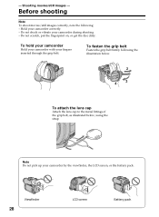
... screen, or the battery pack. Before shooting Note To shoot movies/still images correctly, note the following the illustration below. 1 2 4 3 To attach the lens cap Attach the lens cap to the metal fittings of the grip belt, as illustrated below, using the strap. Shooting movies/still images - Viewfinder 28 LCD screen Battery...
... screen, or the battery pack. Before shooting Note To shoot movies/still images correctly, note the following the illustration below. 1 2 4 3 To attach the lens cap Attach the lens cap to the metal fittings of the grip belt, as illustrated below, using the strap. Shooting movies/still images - Viewfinder 28 LCD screen Battery...
Operating Instructions
Page 29
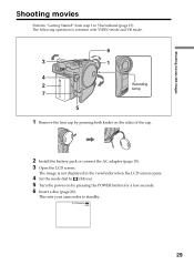
... the LCD screen. This sets your camcorder to 5 beforehand (page 15). The image is common with VIDEO mode and VR mode. 6 3 1 4 2 Recording lamp 7 5 1 Remove the lens cap by pressing the POWER button for a few seconds. 6 Insert a disc (page 26). STBY0:00:00 -R VIDEO 29 Shooting movies/still images Shooting movies Perform...
... the LCD screen. This sets your camcorder to 5 beforehand (page 15). The image is common with VIDEO mode and VR mode. 6 3 1 4 2 Recording lamp 7 5 1 Remove the lens cap by pressing the POWER button for a few seconds. 6 Insert a disc (page 26). STBY0:00:00 -R VIDEO 29 Shooting movies/still images Shooting movies Perform...
Operating Instructions
Page 30
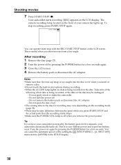
... the recording mode (page 32). •There may be time difference between the point when you press START/STOP and the actual point that the lens cap strap is not caught into the disc cover when you leave your camcorder automatically turns off . - Tip If you insert or remove a disc. •...
... the recording mode (page 32). •There may be time difference between the point when you press START/STOP and the actual point that the lens cap strap is not caught into the disc cover when you leave your camcorder automatically turns off . - Tip If you insert or remove a disc. •...
Operating Instructions
Page 35
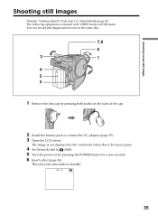
... when the LCD screen opens. 4 Set the mode dial to (Still). 5 Turn the power on by pressing both knobs on the same disc. 7 8 6 3 1 4 2 5 1 Remove the lens cap by pressing the POWER button for a few seconds. 6 Insert a disc (page 26). FINE 0 -R VIDEO 35 Shooting movies/still images Shooting still images Perform "Getting...
... when the LCD screen opens. 4 Set the mode dial to (Still). 5 Turn the power on by pressing both knobs on the same disc. 7 8 6 3 1 4 2 5 1 Remove the lens cap by pressing the POWER button for a few seconds. 6 Insert a disc (page 26). FINE 0 -R VIDEO 35 Shooting movies/still images Shooting still images Perform "Getting...
Operating Instructions
Page 112
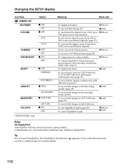
...BURST* z OFF NORMAL EXP BRKTG QUALITY z FINE STANDARD IMAGESIZE* z 1152 ✕ 864 N.S.LIGHT * DCR-DVD201 only 640 ✕ 480 z ON OFF Meaning Mode dial To disable self-timer. To deactivate ... SteadyShot •SteadyShot will not correct excessive camera shake. •Attachment of a conversion lens (optional) may influence SteadyShot. Your camcorder prevents 112 To compensate for camera-shake....continuously with a tripod. To use NightShot Light (page 45). Not to record 16:9 Wide picture. To record still images in 640 ✕ 480 size. To record still images...
...BURST* z OFF NORMAL EXP BRKTG QUALITY z FINE STANDARD IMAGESIZE* z 1152 ✕ 864 N.S.LIGHT * DCR-DVD201 only 640 ✕ 480 z ON OFF Meaning Mode dial To disable self-timer. To deactivate ... SteadyShot •SteadyShot will not correct excessive camera shake. •Attachment of a conversion lens (optional) may influence SteadyShot. Your camcorder prevents 112 To compensate for camera-shake....continuously with a tripod. To use NightShot Light (page 45). Not to record 16:9 Wide picture. To record still images in 640 ✕ 480 size. To record still images...

Operating Instructions
Page 120
The disc cannot be recorded additionally on the viewfinder screen is not clear. • The viewfinder lens is not adjusted. c Adjust the viewfinder lens. (page 22) The picture does not appear in the • The LCD screen is not a malfunction. This is open. This is set the mode dial ...
The disc cannot be recorded additionally on the viewfinder screen is not clear. • The viewfinder lens is not adjusted. c Adjust the viewfinder lens. (page 22) The picture does not appear in the • The LCD screen is not a malfunction. This is open. This is set the mode dial ...

Operating Instructions
Page 132
...You bring your camcorder, on moisture condensation Moisture may condense when you bring your camcorder from a cold place into a place warmed up by a Sony dealer before operating it . Under the hot sun or inside a car when the windows are not using your camcorder. If there is moisture ... a shower. •You use or not, avoid leaving your camcorder in the following locations. This is not a malfunction. Note on the surface of the lens. •Keep the POWER to off your camcorder may be done correctly. Be particularly careful of the disc, or on 7.2 V (battery pack) or ...
...You bring your camcorder, on moisture condensation Moisture may condense when you bring your camcorder from a cold place into a place warmed up by a Sony dealer before operating it . Under the hot sun or inside a car when the windows are not using your camcorder. If there is moisture ... a shower. •You use or not, avoid leaving your camcorder in the following locations. This is not a malfunction. Note on the surface of the lens. •Keep the POWER to off your camcorder may be done correctly. Be particularly careful of the disc, or on 7.2 V (battery pack) or ...

Operating Instructions
Page 133
...and it with a dry cloth. •To prevent the camcorder body from being damaged, avoid followings; - Pickup lens •When the camcorder does not work because the pickup lens is exposed to salty air such as at the seaside. •Store in a well-ventilated location subject to direct... sunlight The internal mechanisms of the lens clean with a soft cloth in contact with the above . Maintenance information and precautions •Near a AM receivers and video equipment. Periodically ...
...and it with a dry cloth. •To prevent the camcorder body from being damaged, avoid followings; - Pickup lens •When the camcorder does not work because the pickup lens is exposed to salty air such as at the seaside. •Store in a well-ventilated location subject to direct... sunlight The internal mechanisms of the lens clean with a soft cloth in contact with the above . Maintenance information and precautions •Near a AM receivers and video equipment. Periodically ...
Operating Instructions
Page 135
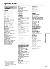
...) main unit only 605 g (15 oz) including the battery pack, disc and lens cap Supplied accessories See page 14. Additional information 135 Lens Carl Zeiss Vario-Tessar Filter diameter: 25 mm (1 in.) 10× (Optical), 120× (Digital) DCR-DVD101: F = 1.7 - 2.3 DCR-DVD201: F = 1.8 - 2.3 Focal length DCR-DVD101: 2.3 - 23 mm (3/32 - 15/16 in.) When converted to a 35 mm...
...) main unit only 605 g (15 oz) including the battery pack, disc and lens cap Supplied accessories See page 14. Additional information 135 Lens Carl Zeiss Vario-Tessar Filter diameter: 25 mm (1 in.) 10× (Optical), 120× (Digital) DCR-DVD101: F = 1.7 - 2.3 DCR-DVD201: F = 1.8 - 2.3 Focal length DCR-DVD101: 2.3 - 23 mm (3/32 - 15/16 in.) When converted to a 35 mm...
Operating Instructions
Page 137
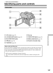
... the MTF* measurement system for video cameras and offers the same quality as a Carl Zeiss lens. * MTF stands for shoulder strap Note on the Carl Zeiss lens Your camcorder is equipped with a Carl Zeiss lens which can reproduce fine images. Identifying parts and controls Camcorder 1 5 6 2 7 8 ... button (page 30) 8 Battery attachment (page 15) 9 Hooks for Modulation Transfer Function. The lens for your camcorder was developed jointly by Carl Zeiss, in Germany, and Sony Corporation. Parts and controls/Index - The value number indicates the amount of light from a subject coming...
... the MTF* measurement system for video cameras and offers the same quality as a Carl Zeiss lens. * MTF stands for shoulder strap Note on the Carl Zeiss lens Your camcorder is equipped with a Carl Zeiss lens which can reproduce fine images. Identifying parts and controls Camcorder 1 5 6 2 7 8 ... button (page 30) 8 Battery attachment (page 15) 9 Hooks for Modulation Transfer Function. The lens for your camcorder was developed jointly by Carl Zeiss, in Germany, and Sony Corporation. Parts and controls/Index - The value number indicates the amount of light from a subject coming...

Operating Instructions
Page 138
Otherwise, you cannot attach the tripod securely, and the screw may damage your camcorder. 138 qh qa qs qj qd qf qg qk q; Mode dial (page 19) qa POWER/CHG lamp (page 16) qs REMOTE jack Use to connect to optional accessories. Identifying parts and controls q; qd Viewfinder lens adjustment dial (page 22) qf POWER button (page 19) qg BATT (battery) release button (page 15) qh DC IN jack (page 16) qj Lens cap (page 28) qk Tripod receptacle Make sure that the length of the tripod screw is less than 5.5 mm (7/32 inch).
Otherwise, you cannot attach the tripod securely, and the screw may damage your camcorder. 138 qh qa qs qj qd qf qg qk q; Mode dial (page 19) qa POWER/CHG lamp (page 16) qs REMOTE jack Use to connect to optional accessories. Identifying parts and controls q; qd Viewfinder lens adjustment dial (page 22) qf POWER button (page 19) qg BATT (battery) release button (page 15) qh DC IN jack (page 16) qj Lens cap (page 28) qk Tripod receptacle Make sure that the length of the tripod screw is less than 5.5 mm (7/32 inch).

Operating Instructions
Page 139
... and push it is linked to the POWER button, allowing you to turn the power supplied by the shoe on and off. Shoe cover wa Lens ws Remote sensor/Infrared ray emitter wd MIC (PLUG IN POWER) jack Connect an external microphone (optional). Refer to optional accessories such as a microphone. •...
... and push it is linked to the POWER button, allowing you to turn the power supplied by the shoe on and off. Shoe cover wa Lens ws Remote sensor/Infrared ray emitter wd MIC (PLUG IN POWER) jack Connect an external microphone (optional). Refer to optional accessories such as a microphone. •...
Operating Instructions
Page 145
... color systems 12, 131 Unfinalize 72 USB jack 94 VCR 106 VIDEO mode 7 Viewfinder 22 Viewfinder lens adjustment 22 Visual Index 56 VR mode 7 W, X, Y, Z Warning indicators 126 Warning messages 127 White balance 50 Wide-angle 33 Wide mode 48 WIPE 53 Zoom 33, 61 Parts and controls/Index 145 See Beep OVERLAP 53...
... color systems 12, 131 Unfinalize 72 USB jack 94 VCR 106 VIDEO mode 7 Viewfinder 22 Viewfinder lens adjustment 22 Visual Index 56 VR mode 7 W, X, Y, Z Warning indicators 126 Warning messages 127 White balance 50 Wide-angle 33 Wide mode 48 WIPE 53 Zoom 33, 61 Parts and controls/Index 145 See Beep OVERLAP 53...


