
Operating Instructions
Page 3
controllable Cameras in Memory - BR300 Remote Control Unit 11 Operating Multiple BRC-Z700 Cameras Using the RM-BR300 Remote Control Unit 12 Operating a BRC-Z700 Camera from a Long Distance 13 Operating Multiple BRC-Z700 Cameras from a Long Distance 14 Using BRC-Z700 Cameras and VISCA- Table of Contents Getting Started Precautions 5 Phenomena Specific to the HDV Video Equipment 17 Location and Function of Contents Presetting Feature 45 Operation ...
controllable Cameras in Memory - BR300 Remote Control Unit 11 Operating Multiple BRC-Z700 Cameras Using the RM-BR300 Remote Control Unit 12 Operating a BRC-Z700 Camera from a Long Distance 13 Operating Multiple BRC-Z700 Cameras from a Long Distance 14 Using BRC-Z700 Cameras and VISCA- Table of Contents Getting Started Precautions 5 Phenomena Specific to the HDV Video Equipment 17 Location and Function of Contents Presetting Feature 45 Operation ...

Operating Instructions
Page 4
...61 Connecting to a Preset Position 52 Installation and Connections Installation 53 Attaching an Interface Board 53 Installing the Camera 53 Installing the Camera in Memory - Adjusting the Camera 49 Focusing on a Subject 49 Shooting with HD-SDI Input Connectors 66 Connecting the BRU-H700 HD Optical...Using the VISCA RS-422 Connector Plug ...... 90 4 Table of the Camera Moving to an AC Outlet 61 Connecting the RM-BR300 Remote Control Unit 62 Connecting a Monitor, etc. Presetting Feature 51 Storing Camera Settings 51 Setting the Speed of Contents Equipped with the Analog Component (...
...61 Connecting to a Preset Position 52 Installation and Connections Installation 53 Attaching an Interface Board 53 Installing the Camera 53 Installing the Camera in Memory - Adjusting the Camera 49 Focusing on a Subject 49 Shooting with HD-SDI Input Connectors 66 Connecting the BRU-H700 HD Optical...Using the VISCA RS-422 Connector Plug ...... 90 4 Table of the Camera Moving to an AC Outlet 61 Connecting the RM-BR300 Remote Control Unit 62 Connecting a Monitor, etc. Presetting Feature 51 Storing Camera Settings 51 Setting the Speed of Contents Equipped with the Analog Component (...
Operating Instructions
Page 6
...-M100HG Optical Fiber Cable and BRU-H700 Optical Multiplex Unit, and Sony's unique camera connection technology and optical digital multiplex transmission technology allows a long distance transmission of camera images up to 7 cameras can be switched (1080/59.94i or 1080/50i) with a... • The optional RM-BR300 Remote Control Unit allows easy camera operations. 6 Features VISCA camera protocol supported • The camera is enabled. Built-in interface card slot The camera is equivalent to a 35-mm camera). Built-in down-converted output The camera is equipped with high contrast and...
...-M100HG Optical Fiber Cable and BRU-H700 Optical Multiplex Unit, and Sony's unique camera connection technology and optical digital multiplex transmission technology allows a long distance transmission of camera images up to 7 cameras can be switched (1080/59.94i or 1080/50i) with a... • The optional RM-BR300 Remote Control Unit allows easy camera operations. 6 Features VISCA camera protocol supported • The camera is enabled. Built-in interface card slot The camera is equivalent to a 35-mm camera). Built-in down-converted output The camera is equipped with high contrast and...

Operating Instructions
Page 8
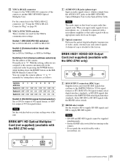
... power adaptor (1), AC power cord (1), RS-232C connecting cable (3 m) (1), RS-422 connector plug (2) BRBK-MF1 HD Optical Multiplex Card Insert the card into the camera to seven cameras. The Remote Control Unit also allows remote operation of the Remote Control Unit allows you comfortable pan/tilt and zoom operations. Ceiling bracket (A) (1) Operating Instructions (1) Optional Products RM-BR300...
... power adaptor (1), AC power cord (1), RS-232C connecting cable (3 m) (1), RS-422 connector plug (2) BRBK-MF1 HD Optical Multiplex Card Insert the card into the camera to seven cameras. The Remote Control Unit also allows remote operation of the Remote Control Unit allows you comfortable pan/tilt and zoom operations. Ceiling bracket (A) (1) Operating Instructions (1) Optional Products RM-BR300...
Operating Instructions
Page 11
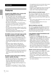
... (supplied) Video signal Signal flow Operating a BRC-Z700 Camera Using the RM-BR300 Remote Control Unit This system allows you : To operate the camera readily from a short distance System configuration BRC-Z700 HD video monitor, VTR, etc. BRC-Z700 RM-BR300 Remote Control Unit Video signal Remote Control (VISCA) signal , Signal flow 11 System Configuration This section describes eight typical system examples with the...
... (supplied) Video signal Signal flow Operating a BRC-Z700 Camera Using the RM-BR300 Remote Control Unit This system allows you : To operate the camera readily from a short distance System configuration BRC-Z700 HD video monitor, VTR, etc. BRC-Z700 RM-BR300 Remote Control Unit Video signal Remote Control (VISCA) signal , Signal flow 11 System Configuration This section describes eight typical system examples with the...

Operating Instructions
Page 12
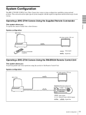
Overview Operating Multiple BRC-Z700 Cameras Using the RM-BR300 Remote Control Unit This system allows you: • To operate up to seven cameras remotely using a single Remote Control Unit • To perform pan/tilt and zoom operations using the joystick System configuration BRC-Z700 HD video monitor, VTR, etc. BRC-Z700 BRC-Z700 Video switcher RM-BR300 Remote Control Unit Video signal Remote control (VISCA) signal Tally/contact signal , Signal flow 12 System Configuration
Overview Operating Multiple BRC-Z700 Cameras Using the RM-BR300 Remote Control Unit This system allows you: • To operate up to seven cameras remotely using a single Remote Control Unit • To perform pan/tilt and zoom operations using the joystick System configuration BRC-Z700 HD video monitor, VTR, etc. BRC-Z700 BRC-Z700 Video switcher RM-BR300 Remote Control Unit Video signal Remote control (VISCA) signal Tally/contact signal , Signal flow 12 System Configuration

Operating Instructions
Page 13
... Unit to turn on the power of the BRC-Z700 camera before you : • To operate the camera remotely from a distance up to 1,000 m (3,281 feet) • To perform pan/tilt and zoom operations using the joystick • To transmit the video signal and control signal of the camera to a distant place using the CCFC-M100HG Optical...
... Unit to turn on the power of the BRC-Z700 camera before you : • To operate the camera remotely from a distance up to 1,000 m (3,281 feet) • To perform pan/tilt and zoom operations using the joystick • To transmit the video signal and control signal of the camera to a distant place using the CCFC-M100HG Optical...

Operating Instructions
Page 14
... BRU-H700 Video switcher CCFC-M100HG BRBK-MF1 Video signal Remote control (VISCA) signal Tally/contact signal , Signal flow BRU-H700 RM-BR300 Remote Control Unit 14 System Configuration Overview Operating Multiple BRC-Z700 Cameras from a Long Distance This system allows you: • To operate up to seven cameras remotely from a distance up to 1,000 m (3,281 feet) • To...
... BRU-H700 Video switcher CCFC-M100HG BRBK-MF1 Video signal Remote control (VISCA) signal Tally/contact signal , Signal flow BRU-H700 RM-BR300 Remote Control Unit 14 System Configuration Overview Operating Multiple BRC-Z700 Cameras from a Long Distance This system allows you: • To operate up to seven cameras remotely from a distance up to 1,000 m (3,281 feet) • To...

Operating Instructions
Page 15
... and zoom operations using the joystick • To control the BRC-Z700 cameras remotely from a distance up to 1,000 m (3,281 feet) by transmitting the video signal and control signal using the Optical Fiber Cable System configuration VISCA-controllable camera HD video monitor, VTR, etc. VISCA-controllable camera BRC-Z700 CCFC-M100HG BRU-H700 BRC-Z700 BRBK-MF1 CCFC-M100HG Optical Fiber Cable BRBK-MF1...
... and zoom operations using the joystick • To control the BRC-Z700 cameras remotely from a distance up to 1,000 m (3,281 feet) by transmitting the video signal and control signal using the Optical Fiber Cable System configuration VISCA-controllable camera HD video monitor, VTR, etc. VISCA-controllable camera BRC-Z700 CCFC-M100HG BRU-H700 BRC-Z700 BRBK-MF1 CCFC-M100HG Optical Fiber Cable BRBK-MF1...

Operating Instructions
Page 16
... camera remotely from a distance up to 1,000m (3,281 feet) • To perform pan/tilt and zoom operations using the joystick • To transmit the video signal and control signal of the camera, and the audio signal input to the BRBK-MF1 Optical Multiplex Card to a distant place using the Optical Fiber Cable System configuration BRC-Z700...
... camera remotely from a distance up to 1,000m (3,281 feet) • To perform pan/tilt and zoom operations using the joystick • To transmit the video signal and control signal of the camera, and the audio signal input to the BRBK-MF1 Optical Multiplex Card to a distant place using the Optical Fiber Cable System configuration BRC-Z700...

Operating Instructions
Page 17
...operate the camera remotely from a distance up to 1,000m (3,281 feet) • To perform pan/tilt and zoom operations using the joystick • To transmit the video signal and control signal of the camera and the audio signal input to the HDV video equipment System configuration BRC-Z700 Microphone BRBK-... Unit (rear) Video signal Audio line signal Remote control (VISCA) signal , Signal flow RM-BR300 Remote Control Unit Notes • The video signal delay in this system is adjustable by signal processing in the HDV menu of the camera to compensate for the delay between the video ...
...operate the camera remotely from a distance up to 1,000m (3,281 feet) • To perform pan/tilt and zoom operations using the joystick • To transmit the video signal and control signal of the camera and the audio signal input to the HDV video equipment System configuration BRC-Z700 Microphone BRBK-... Unit (rear) Video signal Audio line signal Remote control (VISCA) signal , Signal flow RM-BR300 Remote Control Unit Notes • The video signal delay in this system is adjustable by signal processing in the HDV menu of the camera to compensate for the delay between the video ...

Operating Instructions
Page 18
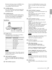
... to overlap the menu. With this camera is in the middle of a daisy chain connection of the camera does not function. Set it to OFF not to the RM-BR300 Remote Control Unit (not supplied). K IR SELECT switch Select the camera number when you use the upper remote sensor, set to ON in the ... daisy chain connection. 18 Location and Function of the tally lamp. qd qf qg qhqjqk ql G VISCA RS-422 connector Used for the supplied Remote Commander. D SONY and HD nameplates Pull them out to the VISCA RS-422 connector, see "Using the VISCA RS-422 Connector Plug" on page 90. L ...
... to overlap the menu. With this camera is in the middle of a daisy chain connection of the camera does not function. Set it to OFF not to the RM-BR300 Remote Control Unit (not supplied). K IR SELECT switch Select the camera number when you use the upper remote sensor, set to ON in the ... daisy chain connection. 18 Location and Function of the tally lamp. qd qf qg qhqjqk ql G VISCA RS-422 connector Used for the supplied Remote Commander. D SONY and HD nameplates Pull them out to the VISCA RS-422 connector, see "Using the VISCA RS-422 Connector Plug" on page 90. L ...

Operating Instructions
Page 19
... as S video signal. The slot cover is not used. in a High Position" on the RMBR300 Remote Control Unit. Normally set to these holes. You can assign the camera address "1" to "7" manually by pressing the POWER button while holding down the RESET button on page 55. Bottom w; R Card slot ...Communication baud rate selector) Set to ON for 38400bps, or OFF for the output signal format selection, RS232C/RS-422 selection, baud rate selection, remote control signal output on page 19. The four feet are assigned to the cameras automatically in the daisy chain connection.
... as S video signal. The slot cover is not used. in a High Position" on the RMBR300 Remote Control Unit. Normally set to these holes. You can assign the camera address "1" to "7" manually by pressing the POWER button while holding down the RESET button on page 55. Bottom w; R Card slot ...Communication baud rate selector) Set to ON for 38400bps, or OFF for the output signal format selection, RS232C/RS-422 selection, baud rate selection, remote control signal output on page 19. The four feet are assigned to the cameras automatically in the daisy chain connection.
Operating Instructions
Page 21
...details, see "Functions of the RM-BR300 Remote Control Unit when it is lit, the function of the control varies according to select the function of the camera. For details, see "Functions of the camera. RM-BR300 Remote Control Unit (not supplied) This manual explains the ...adjustment mode is selected with the MODE button (with BRC-Z700 cameras. F AUTO/MANUAL button and AUTO indicator Press this control counterclockwise (toward FAR) to the Operating Instructions supplied with other cameras, refer to focus on the camera. When the white balance adjustment mode is selected, ...
...details, see "Functions of the RM-BR300 Remote Control Unit when it is lit, the function of the control varies according to select the function of the camera. For details, see "Functions of the camera. RM-BR300 Remote Control Unit (not supplied) This manual explains the ...adjustment mode is selected with the MODE button (with BRC-Z700 cameras. F AUTO/MANUAL button and AUTO indicator Press this control counterclockwise (toward FAR) to the Operating Instructions supplied with other cameras, refer to focus on the camera. When the white balance adjustment mode is selected, ...
Operating Instructions
Page 23
... the Remote Control Unit is attached at the factory. Select the function of the TALLY/CONTACT connector. CONTACT(TALLY) TALLY 1 9 1 9 CONTACT DC IN 12V ON/OFF wa ws wd wf wg wh wj wk U MODE selector Select the position corresponding to the VISCAcontrollable camera to position 7 when all the connected cameras are BRC-Z700s. Switch position 0 1 2 3 4 5 6 7 Camera...
... the Remote Control Unit is attached at the factory. Select the function of the TALLY/CONTACT connector. CONTACT(TALLY) TALLY 1 9 1 9 CONTACT DC IN 12V ON/OFF wa ws wd wf wg wh wj wk U MODE selector Select the position corresponding to the VISCAcontrollable camera to position 7 when all the connected cameras are BRC-Z700s. Switch position 0 1 2 3 4 5 6 7 Camera...

Operating Instructions
Page 24
..., see "List of the BRBKH700 HD Optical Multiplex Card installed in the BRC-H700 camera using the CCFC-M100HG Optical Fiber Cable. G CAMERA connector Connect to the VISCA RS-232C IN connector of the next camera in the daisy chain connection. 24 Location and Function of the previous... camera in red: Abnormal operation of the BRC-H700 camera before you turn on the HD Optical Multiplex Unit. I EXT SYNC OUT connector Supplies external video sync signals input from the installed Interface Board. When you connect multiple cameras, connect it to OFF not to the RM-BR300 Remote Control ...
..., see "List of the BRBKH700 HD Optical Multiplex Card installed in the BRC-H700 camera using the CCFC-M100HG Optical Fiber Cable. G CAMERA connector Connect to the VISCA RS-232C IN connector of the next camera in the daisy chain connection. 24 Location and Function of the previous... camera in red: Abnormal operation of the BRC-H700 camera before you turn on the HD Optical Multiplex Unit. I EXT SYNC OUT connector Supplies external video sync signals input from the installed Interface Board. When you connect multiple cameras, connect it to OFF not to the RM-BR300 Remote Control ...
Operating Instructions
Page 25
... audio level can assign the camera address "1" to "7" manually by pressing the POWER button while holding down -converted SD-SDI signals that conform to the SMPTE292M serial digital interface standards. Note The audio input on the RMBR300 Remote Control Unit. Select HD-SDI or SD-SDI signals with the BRC-Z700 only) BRBK-H700 1 R L AUDIO...
... audio level can assign the camera address "1" to "7" manually by pressing the POWER button while holding down -converted SD-SDI signals that conform to the SMPTE292M serial digital interface standards. Note The audio input on the RMBR300 Remote Control Unit. Select HD-SDI or SD-SDI signals with the BRC-Z700 only) BRBK-H700 1 R L AUDIO...

Operating Instructions
Page 28
...monitor. For the overall menu configurations, see page 73. BR300 Remote Control Unit once displays PAGE1 and pressing it twice displays PAGE2. 4 Option borad indicator Displays the name of the interface board inserted into the card slot of the camera. (The illustration above shows an example when the BRBK-HSD1...or the joystick of the RM-BR300 Remote Control Unit, and press the HOME button on the Remote Commander or the top button of the joystick on the RM-BR300. 3 Page number Displays the first page (PAGE1) or second page (PAGE2) of the camera, while observing menus displayed on -...
...monitor. For the overall menu configurations, see page 73. BR300 Remote Control Unit once displays PAGE1 and pressing it twice displays PAGE2. 4 Option borad indicator Displays the name of the interface board inserted into the card slot of the camera. (The illustration above shows an example when the BRBK-HSD1...or the joystick of the RM-BR300 Remote Control Unit, and press the HOME button on the Remote Commander or the top button of the joystick on the RM-BR300. 3 Page number Displays the first page (PAGE1) or second page (PAGE2) of the camera, while observing menus displayed on -...

Operating Instructions
Page 29
...selected on the main menu is displayed here. 2 Cursor Selects a setting item. PAGE 1 of the RM-BR300 Remote Control Unit, and press the B or b button on the Remote Commander or incline the joystick on the RMBR300 right or left. 4 Set value The currently set values are displayed... OFF SYNC MASTER STD H PHASE 10 Operation Through Menus This section explains how to operate the menu using the supplied Remote Commander, or using the V or v button on page 73. 1 POWER CAMERA SELECT 2 1 FOCUS 3 MANUAL NEAR BACK LIGHT FAR AUTO DATA SCREEN 3 REV 2 6 STD RESET 1 4 5 PRESET ...
...selected on the main menu is displayed here. 2 Cursor Selects a setting item. PAGE 1 of the RM-BR300 Remote Control Unit, and press the B or b button on the Remote Commander or incline the joystick on the RMBR300 right or left. 4 Set value The currently set values are displayed... OFF SYNC MASTER STD H PHASE 10 Operation Through Menus This section explains how to operate the menu using the supplied Remote Commander, or using the V or v button on page 73. 1 POWER CAMERA SELECT 2 1 FOCUS 3 MANUAL NEAR BACK LIGHT FAR AUTO DATA SCREEN 3 REV 2 6 STD RESET 1 4 5 PRESET ...

Operating Instructions
Page 30
... Adjusting and Setting With Menus 2 Move the cursor to the menu item to be set by pressing the B or b button. Menu Operation Using the RMBR300 Remote Control Unit 1 2,4,5 VALUE LOCK - + R BRIGHT MODE - + B FOCUS AUTO AUTO MANUAL NEAR FAR ONE PUSH AF RESET PRESET SHIFT L/R DIRECTION POWER PANEL... LIGHT BLACK PAN-TILT ONE PUSH LIGHT RESET AWB MENU POSITION 12345678 9 10 11 12 13 14 15 16 STD REV CAMERA 1234567 3 1 Press the MENU button for about one second. The selected menu appears. >IR-RECEIVE ON IMG-FLIP OFF PAN REVERSE ...
... Adjusting and Setting With Menus 2 Move the cursor to the menu item to be set by pressing the B or b button. Menu Operation Using the RMBR300 Remote Control Unit 1 2,4,5 VALUE LOCK - + R BRIGHT MODE - + B FOCUS AUTO AUTO MANUAL NEAR FAR ONE PUSH AF RESET PRESET SHIFT L/R DIRECTION POWER PANEL... LIGHT BLACK PAN-TILT ONE PUSH LIGHT RESET AWB MENU POSITION 12345678 9 10 11 12 13 14 15 16 STD REV CAMERA 1234567 3 1 Press the MENU button for about one second. The selected menu appears. >IR-RECEIVE ON IMG-FLIP OFF PAN REVERSE ...