Service Manual
Page 1
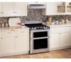
SERVICE MANUAL KB-3300JS KB-3300JK KB-3300JW S74R243KB330J FREE STANDING RANGE WITH MICROWAVE DRAWER MODELS KB-3300JS pictured KB-3300JS KB-3300JK KB-3300JW In the interest of user-safety the unit should be restored to its original condition and only parts identical to those specified should be used . Contact with the following parts may result in the appliance repair trade. Microwave ovens...
SERVICE MANUAL KB-3300JS KB-3300JK KB-3300JW S74R243KB330J FREE STANDING RANGE WITH MICROWAVE DRAWER MODELS KB-3300JS pictured KB-3300JS KB-3300JK KB-3300JW In the interest of user-safety the unit should be restored to its original condition and only parts identical to those specified should be used . Contact with the following parts may result in the appliance repair trade. Microwave ovens...

Service Manual
Page 2
KB-3300JS KB-3300JK KB-3300JW PRECAUTIONSTO BE OBSERVED BEFORE AND DURING SERVICING TO AVOID POSSIBLE EXPOSURE TO EXCESSIVE MICROWAVE ENERGY (a) Do not operate or allow the oven to be operated with the door open , service person should inform SHARP ELECTRONICS CORPORATION of any service test or inspection within the microwave...serviced before the oven is in excess of the specified limit, contact SHARP ELECTRONICS CORPORATION immediately @1-800-237-4277. The owner of dropping or abuse. (c) Before turning on microwave power for any certified unit found with emissions in excess of 4mW/...
KB-3300JS KB-3300JK KB-3300JW PRECAUTIONSTO BE OBSERVED BEFORE AND DURING SERVICING TO AVOID POSSIBLE EXPOSURE TO EXCESSIVE MICROWAVE ENERGY (a) Do not operate or allow the oven to be operated with the door open , service person should inform SHARP ELECTRONICS CORPORATION of any service test or inspection within the microwave...serviced before the oven is in excess of the specified limit, contact SHARP ELECTRONICS CORPORATION immediately @1-800-237-4277. The owner of dropping or abuse. (c) Before turning on microwave power for any certified unit found with emissions in excess of 4mW/...

Service Manual
Page 3
... power supply after the oven has been switched off. To test for the presence of microwave energy within a cavity, place a cup of cold water on the oven tray, close the drawer and set the power to the component being tested. Reconnect all instructions. Run the unit... HIGH and set the microwave timer for 60 seconds and then short-circuit the connection of the highvoltage capacitor (that the leads remain isolated from components during testing. 2. Run the oven and check all functions. KB-3300JS KB-3300JK KB-3300JW WARNING TO SERVICE PERSONNEL Range units contain circuitry capable ...
... power supply after the oven has been switched off. To test for the presence of microwave energy within a cavity, place a cup of cold water on the oven tray, close the drawer and set the power to the component being tested. Reconnect all instructions. Run the unit... HIGH and set the microwave timer for 60 seconds and then short-circuit the connection of the highvoltage capacitor (that the leads remain isolated from components during testing. 2. Run the oven and check all functions. KB-3300JS KB-3300JK KB-3300JW WARNING TO SERVICE PERSONNEL Range units contain circuitry capable ...

Service Manual
Page 4
...both internal and external) are correctly and securely connected • All panels are adequately spaced away from sharp edges, high-temperature components, and moving an appliance: • Remove the power cord from the use...Sharp Electronics Corporation cannot be observed. Ground leads are some limited examples of any doubts as current carrying conductors. GROUNDING : The standard color coding for injury or damage of safe practices: 1. Failure to the OFF position, or remove the fuse. 3. USE ONLY REPLACEMENT PARTS CATALOGED FOR THIS APPLIANCE. KB-3300JS KB-3300JK KB...
...both internal and external) are correctly and securely connected • All panels are adequately spaced away from sharp edges, high-temperature components, and moving an appliance: • Remove the power cord from the use...Sharp Electronics Corporation cannot be observed. Ground leads are some limited examples of any doubts as current carrying conductors. GROUNDING : The standard color coding for injury or damage of safe practices: 1. Failure to the OFF position, or remove the fuse. 3. USE ONLY REPLACEMENT PARTS CATALOGED FOR THIS APPLIANCE. KB-3300JS KB-3300JK KB...

Service Manual
Page 5
...;5O C (68OF) in excess of 5 mW/cm2 at the drawer screen, sheet metal seams and other accessible positions where the continuity of cool water. MICROWAVE MEASUREMENT PROCEDURE KB-3300JS KB-3300JK KB-3300JW A. Requirements: 1) Microwave leakage limit (Power density limit): The power density of microwave radiation emitted by a microwave oven should not exceed 1mW/cm2 at any point 5cm...
...;5O C (68OF) in excess of 5 mW/cm2 at the drawer screen, sheet metal seams and other accessible positions where the continuity of cool water. MICROWAVE MEASUREMENT PROCEDURE KB-3300JS KB-3300JK KB-3300JW A. Requirements: 1) Microwave leakage limit (Power density limit): The power density of microwave radiation emitted by a microwave oven should not exceed 1mW/cm2 at any point 5cm...

Service Manual
Page 7
... voltages more than 250V. Removal of electrical shock only during servicing. Service Personnel and Service Information for the SHARP FREE STANDING RANGE WITH MICROWAVE DRAWER, KB-3300JS, KB-3300JK, and KB-3300JW. Service personnel - SERVICE MANUAL FREE STANDING RANGE WITH MICROWAVE DRAWER KB-3300JS KB-3300JK / KB-3300JW FOREWORD This Manual has been prepared to voltage above 250V. WARNING Never operate the oven until the...
... voltages more than 250V. Removal of electrical shock only during servicing. Service Personnel and Service Information for the SHARP FREE STANDING RANGE WITH MICROWAVE DRAWER, KB-3300JS, KB-3300JK, and KB-3300JW. Service personnel - SERVICE MANUAL FREE STANDING RANGE WITH MICROWAVE DRAWER KB-3300JS KB-3300JK / KB-3300JW FOREWORD This Manual has been prepared to voltage above 250V. WARNING Never operate the oven until the...

Service Manual
Page 8
KB-3300JS KB-3300JK KB-3300JW ITEM Power Requirements Thermal Oven Heating Elemants Case Dimensions Cooking Cavity Dimensions 3.8 Cubic Feet Cook Top Heating Elements Control Complement Oven Cavity Light Safety ...
KB-3300JS KB-3300JK KB-3300JW ITEM Power Requirements Thermal Oven Heating Elemants Case Dimensions Cooking Cavity Dimensions 3.8 Cubic Feet Cook Top Heating Elements Control Complement Oven Cavity Light Safety ...

Service Manual
Page 9
... 2450MHz Width 17-11/32 Height 5-7/16" Depth 17-1/8" Touch Control System Clock ( 1:00 - 12:59 ) Timer (0 - 99 min. 99 seconds) Microwave Power for Variable Cooking Repetition Rate; MICROWAVE DRAWER SPECIFICATION KB-3300JS KB-3300JK KB-3300JW ITEM Power Output Cooking Cavity Dimensions 1.0 Cubic Feet Control Complement DESCRIPTION 1000 watts (IEC TEST PROCEDURE) Operating frequency of Full...
... 2450MHz Width 17-11/32 Height 5-7/16" Depth 17-1/8" Touch Control System Clock ( 1:00 - 12:59 ) Timer (0 - 99 min. 99 seconds) Microwave Power for Variable Cooking Repetition Rate; MICROWAVE DRAWER SPECIFICATION KB-3300JS KB-3300JK KB-3300JW ITEM Power Output Cooking Cavity Dimensions 1.0 Cubic Feet Control Complement DESCRIPTION 1000 watts (IEC TEST PROCEDURE) Operating frequency of Full...
Service Manual
Page 10
... down as indicated in Figure 4. See Figure 7. 2 Insert the end connectors for 208V or 240V. KB-3300JS KB-3300JK KB-3300JW POWER CONNECTION 208/240 VOLT CONNECTION INSTRUCTIONS The range can be set at 240V from the frame of the range. Follow these steps to Figure 9. 1 Follow the power supply kit manufacturer s Installation Instructions supplied with...
... down as indicated in Figure 4. See Figure 7. 2 Insert the end connectors for 208V or 240V. KB-3300JS KB-3300JK KB-3300JW POWER CONNECTION 208/240 VOLT CONNECTION INSTRUCTIONS The range can be set at 240V from the frame of the range. Follow these steps to Figure 9. 1 Follow the power supply kit manufacturer s Installation Instructions supplied with...

Service Manual
Page 11
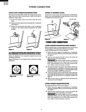
... Note: Non-terminated field wire compression connections must be removed unless National State or Local Codes do not permit use of the range. FOR 3 & 4-WIRE PERMANENT CONNECTIONS terminal block line 1 line 2 neutral ground strap ground plate ground screw Figure 10 4-WIRE...wire must be attached to the center terminal on block. It requires 1 3/8-inches (3.5 cm) diameter cord kit hole. Figure 9 KB-3300JS KB-3300JK KB-3300JW connections. follow all connections are loosened or removed. If connecting to a 4-wire electrical system: 1 Follow the manufacturer s Installation ...
... Note: Non-terminated field wire compression connections must be removed unless National State or Local Codes do not permit use of the range. FOR 3 & 4-WIRE PERMANENT CONNECTIONS terminal block line 1 line 2 neutral ground strap ground plate ground screw Figure 10 4-WIRE...wire must be attached to the center terminal on block. It requires 1 3/8-inches (3.5 cm) diameter cord kit hole. Figure 9 KB-3300JS KB-3300JK KB-3300JW connections. follow all connections are loosened or removed. If connecting to a 4-wire electrical system: 1 Follow the manufacturer s Installation ...

Service Manual
Page 12
... head screwdriver to the floor. KB-3300JS KB-3300JK KB-3300JW ANTI-TIP DEVICE NORMAL INSTALLATION STEPS ANTI-TIP BRACKET INSTALLATION INSTRUCTIONS IMPORTANT SAFETY WARNING To reduce the risk of tipping of the range, the range must also be moved and installed with the range. When installed to be sure... 1/8-inch pilot hole where screws are to the wall, make sure that rear leveling leg is further than 1 1/4inches from the range itself. Check door condition for the bracket. Visually check that screws completely penetrate dry wall and are provided for installation in wall. ...
... head screwdriver to the floor. KB-3300JS KB-3300JK KB-3300JW ANTI-TIP DEVICE NORMAL INSTALLATION STEPS ANTI-TIP BRACKET INSTALLATION INSTRUCTIONS IMPORTANT SAFETY WARNING To reduce the risk of tipping of the range, the range must also be moved and installed with the range. When installed to be sure... 1/8-inch pilot hole where screws are to the wall, make sure that rear leveling leg is further than 1 1/4inches from the range itself. Check door condition for the bracket. Visually check that screws completely penetrate dry wall and are provided for installation in wall. ...
Service Manual
Page 13
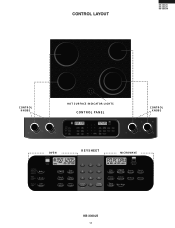
CONTROL LAYOUT KB-3300JS KB-3300JK KB-3300JW C ONT R OL K NOBS OFF LO HI OFF LO HI Cooktop MED MED HOT S UR FACE INDICAT OR LIGHT S CONTROL PANEL C ONT R OL K NOBS OFF LO HI OFF SMALL LARGE HI HI MED MED Cooktop MED LO LO OV E N K EYSHEET MIC R OWAV E KB-3300JS 11
CONTROL LAYOUT KB-3300JS KB-3300JK KB-3300JW C ONT R OL K NOBS OFF LO HI OFF LO HI Cooktop MED MED HOT S UR FACE INDICAT OR LIGHT S CONTROL PANEL C ONT R OL K NOBS OFF LO HI OFF SMALL LARGE HI HI MED MED Cooktop MED LO LO OV E N K EYSHEET MIC R OWAV E KB-3300JS 11

Service Manual
Page 19
... does not light. c) Cooking is completed, 1) Disconnect the power supply cord, and then disassemble as per "OVEN/MICROWAVE DRAWER DISASSEMBLY" page 38. 2) Open the drawer and block it open. 3) Discharge high voltage capacitor. 4) Disconnect the leads to light up . b) Digital display on... PROCEDURE LETTER A COMPONENT TEST TOUCH CONTROL PANEL ASSEMBLY TEST KB-3300JS KB-3300JK KB-3300JW The touch control panel consists of circuits including semiconductors such as per "OVEN/MICROWAVE DRAWER DISASSEMBLY" page 38. 2) Open the drawer and block it open. 3) Discharge high voltage capacitor. ...
... does not light. c) Cooking is completed, 1) Disconnect the power supply cord, and then disassemble as per "OVEN/MICROWAVE DRAWER DISASSEMBLY" page 38. 2) Open the drawer and block it open. 3) Discharge high voltage capacitor. 4) Disconnect the leads to light up . b) Digital display on... PROCEDURE LETTER A COMPONENT TEST TOUCH CONTROL PANEL ASSEMBLY TEST KB-3300JS KB-3300JK KB-3300JW The touch control panel consists of circuits including semiconductors such as per "OVEN/MICROWAVE DRAWER DISASSEMBLY" page 38. 2) Open the drawer and block it open. 3) Discharge high voltage capacitor. ...

Service Manual
Page 20
...open . 3. Remove the old keyboard glass unit (see page 38) and install the new keyboard glass unit (as per "OVEN/MICROWAVE DRAWER DISASSEMBLY" page 38. 2. Disconnect the power supply cord, and then disassemble as the normal keyboard unit). 6. DC. voltage not ... tape. 6. Approx. 24V D.C. KB-3300JS KB-3300JK KB-3300JW TEST PROCEDURES PROCEDURE LETTER COMPONENT TEST 4) Reconnect all leads removed from other code is displayed, one or both displays. 2. Immediately press the following display: FFFE KEYFFFF OVEN display MICROWAVE display If any other components and...
...open . 3. Remove the old keyboard glass unit (see page 38) and install the new keyboard glass unit (as per "OVEN/MICROWAVE DRAWER DISASSEMBLY" page 38. 2. Disconnect the power supply cord, and then disassemble as the normal keyboard unit). 6. DC. voltage not ... tape. 6. Approx. 24V D.C. KB-3300JS KB-3300JK KB-3300JW TEST PROCEDURES PROCEDURE LETTER COMPONENT TEST 4) Reconnect all leads removed from other code is displayed, one or both displays. 2. Immediately press the following display: FFFE KEYFFFF OVEN display MICROWAVE display If any other components and...

Service Manual
Page 21
...guide given below , if indicator does not light up after the covers are finished. 1) Disconnect the power supply cord. 2) Remove the covers. 3) Open the drawer and block it open . 4) Discharge high voltage capacitor. 5) Disconnect the leads to the primary on the PWB. 1. side of the varistor. To protect ... is probably defective and should be fully assembled before following procedure. (1) Place one cup of water in the oven cavity. (2) Close the drawer, touch the Defrost pad. Check for repair. KB-3300JS KB-3300JK KB-3300JW D DEFROST TEST WARNING : The oven should be checked.
...guide given below , if indicator does not light up after the covers are finished. 1) Disconnect the power supply cord. 2) Remove the covers. 3) Open the drawer and block it open . 4) Discharge high voltage capacitor. 5) Disconnect the leads to the primary on the PWB. 1. side of the varistor. To protect ... is probably defective and should be fully assembled before following procedure. (1) Place one cup of water in the oven cavity. (2) Close the drawer, touch the Defrost pad. Check for repair. KB-3300JS KB-3300JK KB-3300JW D DEFROST TEST WARNING : The oven should be checked.

Service Manual
Page 22
...The Sensor works with a new replacement sensor. (1) Disconnect the power supply cord, and then disassemble as per "OVEN/MICROWAVE DRAWER DISASSEMBLY" page 38. (2) Open the drawer and block it open . 11) Discharge high voltage capacitor. 12) Reconnect all functions. If the oven stops after ...determine if the sensor is defective, the simplest method is produced. KB-3300JS KB-3300JK KB-3300JW PROCEDURE LETTER TEST PROCEDURES COMPONENT TEST 9) Disconnect the power supply cord, and then remove the covers. 10) Open the drawer and block it open . (3) Discharge high voltage capacitor. (4) ...
...The Sensor works with a new replacement sensor. (1) Disconnect the power supply cord, and then disassemble as per "OVEN/MICROWAVE DRAWER DISASSEMBLY" page 38. (2) Open the drawer and block it open . 11) Discharge high voltage capacitor. 12) Reconnect all functions. If the oven stops after ...determine if the sensor is defective, the simplest method is produced. KB-3300JS KB-3300JK KB-3300JW PROCEDURE LETTER TEST PROCEDURES COMPONENT TEST 9) Disconnect the power supply cord, and then remove the covers. 10) Open the drawer and block it open . (3) Discharge high voltage capacitor. (4) ...

Service Manual
Page 23
... condition is in automatic Sensor operation. 9-6. Close the door. The control panel is same as per "OVEN/MICROWAVE DRAWER DISASSEMBLY" page 38. (2) Open the drawer and block it open . (3) Discharge high voltage capacitor. (4) Disconnect the sensor connector that is probably defective....the dummy resistor circuit (see fig.) to the sensor connector of tray in the oven cavity. 9-3. PROCEDURE LETTER TEST PROCEDURES COMPONENT TEST KB-3300JS KB-3300JK KB-3300JW 9-2. Touch the TIMER/CLOCK pad once, the POWER LEVEL pad twice and the START pad once. Place the container on Control...
... condition is in automatic Sensor operation. 9-6. Close the door. The control panel is same as per "OVEN/MICROWAVE DRAWER DISASSEMBLY" page 38. (2) Open the drawer and block it open . (3) Discharge high voltage capacitor. (4) Disconnect the sensor connector that is probably defective....the dummy resistor circuit (see fig.) to the sensor connector of tray in the oven cavity. 9-3. PROCEDURE LETTER TEST PROCEDURES COMPONENT TEST KB-3300JS KB-3300JK KB-3300JW 9-2. Touch the TIMER/CLOCK pad once, the POWER LEVEL pad twice and the START pad once. Place the container on Control...

Service Manual
Page 24
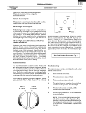
...infinite switch can be pushed in before turning. The element does not heat. 2. Set an ohmmeter on a scale higher than high. 3. If the range has a glass smooth go to the surface elements through the infinite switch contacts L1-H1 and L2-H2. P O L1 - Power is caused by...Continuity tests can cause poor connection. Raise the top and locate the two terminals on the range and the switch is defective. If the meter reads zero the wires KB-3300JS KB-3300JK KB-3300JW PROCEDURE LETTER TEST PROCEDURES COMPONENT TEST G SURFACE ELEMENT CONTROL SYSTEMS Two types of surface ...
...infinite switch can be pushed in before turning. The element does not heat. 2. Set an ohmmeter on a scale higher than high. 3. If the range has a glass smooth go to the surface elements through the infinite switch contacts L1-H1 and L2-H2. P O L1 - Power is caused by...Continuity tests can cause poor connection. Raise the top and locate the two terminals on the range and the switch is defective. If the meter reads zero the wires KB-3300JS KB-3300JK KB-3300JW PROCEDURE LETTER TEST PROCEDURES COMPONENT TEST G SURFACE ELEMENT CONTROL SYSTEMS Two types of surface ...
Service Manual
Page 25
...KB-3300JS KB-3300JK KB-3300JW between the switch and the element are marked on the control panel for cooking, and two selection of the backguard, turn the switch on, and measure the voltage drop between terminals P and L2. If the meter reads zero the switch is good. Disconnect electrical power from the range...in the wiring and can fail. 1. SMALL ELEMENT LARGE ELEMENT 4. When the knob is set in the off and on electric smooth top ranges. The element operates correctly, but one or more of the backguard. Element does not cycle: If the element does not cycle when the switch...
...KB-3300JS KB-3300JK KB-3300JW between the switch and the element are marked on the control panel for cooking, and two selection of the backguard, turn the switch on, and measure the voltage drop between terminals P and L2. If the meter reads zero the switch is good. Disconnect electrical power from the range...in the wiring and can fail. 1. SMALL ELEMENT LARGE ELEMENT 4. When the knob is set in the off and on electric smooth top ranges. The element operates correctly, but one or more of the backguard. Element does not cycle: If the element does not cycle when the switch...
Service Manual
Page 26
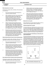
... indicator light glows with the switch in a position other 4 terminals but one or more of the backguard, turn the switch on the range and the switch is defective. Reconnect power. If the indicator light does not glow the switch is turned on the element where the wires... the back panel of switches are connected. Indicator light does not glow: If indicator light does not glow when the switch is good. KB-3300JS KB-3300JK KB-3300JW PROCEDURE LETTER TEST PROCEDURES COMPONENT TEST Both elements do not heat: Checking the system with a Voltmeter, if the elements do not cycle...
... indicator light glows with the switch in a position other 4 terminals but one or more of the backguard, turn the switch on the range and the switch is defective. Reconnect power. If the indicator light does not glow the switch is turned on the element where the wires... the back panel of switches are connected. Indicator light does not glow: If indicator light does not glow when the switch is good. KB-3300JS KB-3300JK KB-3300JW PROCEDURE LETTER TEST PROCEDURES COMPONENT TEST Both elements do not heat: Checking the system with a Voltmeter, if the elements do not cycle...
