DT-500 Operation Manual
Page 2
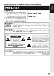
...RISK OF ELECTRIC SHOCK, DO NOT REMOVE COVER. ENGLISH Before using the projector, please read this equipment. Introduction IMPORTANT • For your assistance in the literature accompanying the product. Model No.: DT-500 Serial No.: WARNING: High brightness light source. WARNING: To reduce the... risk of important operating and maintenance (servicing) instructions in reporting the loss or theft of your Projector, please record the Serial Number located on...
...RISK OF ELECTRIC SHOCK, DO NOT REMOVE COVER. ENGLISH Before using the projector, please read this equipment. Introduction IMPORTANT • For your assistance in the literature accompanying the product. Model No.: DT-500 Serial No.: WARNING: High brightness light source. WARNING: To reduce the... risk of important operating and maintenance (servicing) instructions in reporting the loss or theft of your Projector, please record the Serial Number located on...
DT-500 Operation Manual
Page 3
... certain acceptable tolerances that may result in the United States of mercury. This very sophisticated panel contains 983,040 pixels (micromirrors). ONLY Declaration of conformity SHARP PROJECTOR, MODEL DT-500 This device complies with any interference received, including interference that the equipment must conform to run for about 90 seconds after the...
... certain acceptable tolerances that may result in the United States of mercury. This very sophisticated panel contains 983,040 pixels (micromirrors). ONLY Declaration of conformity SHARP PROJECTOR, MODEL DT-500 This device complies with any interference received, including interference that the equipment must conform to run for about 90 seconds after the...
DT-500 Operation Manual
Page 4
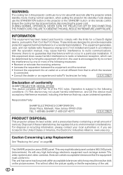
... Picture Fine Sync Options1 Options2 Example: "Picture" screen menu for INPUT 1 mode Selected input mode Menu icons Picture Picture Mode Contrast Bright Color Tint Sharp Red Blue INPUT 1 Standard 0 0 0 0 0 0 0 Note • The "Fine Sync" menu is displayed. SEL./ADJ. Introduction How... to Read this operation manual, the illustration and the screen display are slightly different, depending on the projector. 1 Press dMENU. • The "Picture" menu screen for the selected input mode is displayed. 2 Press Q or O to select...
... Picture Fine Sync Options1 Options2 Example: "Picture" screen menu for INPUT 1 mode Selected input mode Menu icons Picture Picture Mode Contrast Bright Color Tint Sharp Red Blue INPUT 1 Standard 0 0 0 0 0 0 0 Note • The "Fine Sync" menu is displayed. SEL./ADJ. Introduction How... to Read this operation manual, the illustration and the screen display are slightly different, depending on the projector. 1 Press dMENU. • The "Picture" menu screen for the selected input mode is displayed. 2 Press Q or O to select...
DT-500 Operation Manual
Page 5
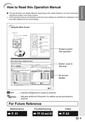
... 10 Part Names and Functions 11 Inserting the Batteries 14 Usable Range 15 Quick Start Quick Start 16 Setup Setting up the Projector 18 Setting up the Projector 18 Standard Setup (Front Projection) ....... 18 Ceiling-mount Setup 18 Projection (PRJ) Mode 19 Picture (Screen) Size and ... Video Equipment ......... 23 Connecting to a Computer 27 Using Basic Operation Turning the Projector On/Off 28 Connecting the Power Cord 28 Turning the Projector on 28 Turning the Power off (Putting the Projector into Standby Mode 29 Image Projection 29 Switching the Input Mode 29 Adjusting the ...
... 10 Part Names and Functions 11 Inserting the Batteries 14 Usable Range 15 Quick Start Quick Start 16 Setup Setting up the Projector 18 Setting up the Projector 18 Standard Setup (Front Projection) ....... 18 Ceiling-mount Setup 18 Projection (PRJ) Mode 19 Picture (Screen) Size and ... Video Equipment ......... 23 Connecting to a Computer 27 Using Basic Operation Turning the Projector On/Off 28 Connecting the Power Cord 28 Turning the Projector on 28 Turning the Power off (Putting the Projector into Standby Mode 29 Image Projection 29 Switching the Input Mode 29 Adjusting the ...
DT-500 Operation Manual
Page 9
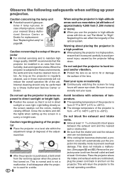
...approximately 4,900 feet (1,500 meters) or more often. Neglecting this projector be installed in high-altitude areas with extremes of the unit. I The storage temperature of the projector is from -4°F to 140°F (-20°C to maintain high image quality, SHARP recommends that it ... reduce the overall operation life of temperature. Caution concerning the setup of the projector I After the projector is purchased, a faint smell from humidity, dust and cigarette smoke. Rest your nearest Sharp Authorized Service Center or Dealer for a while. 8 Avoid locations with thin air...
...approximately 4,900 feet (1,500 meters) or more often. Neglecting this projector be installed in high-altitude areas with extremes of the unit. I The storage temperature of the projector is from -4°F to 140°F (-20°C to maintain high image quality, SHARP recommends that it ... reduce the overall operation life of temperature. Caution concerning the setup of the projector I After the projector is purchased, a faint smell from humidity, dust and cigarette smoke. Rest your nearest Sharp Authorized Service Center or Dealer for a while. 8 Avoid locations with thin air...
DT-500 Operation Manual
Page 10
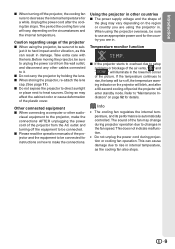
... This can result in damage. The period the cooling fan runs will enter standby mode. ject it . Before moving the projector, be connected for details. Using the projector in other audio- Refer to use an appropriate power cord for a while. The sound of the fan may affect the cabinet... color or cause deformation of the projector from the wall outlet, and disconnect any other cables connected to it to hard impact and/or vibration, as the cooling fan also stops. ...
... This can result in damage. The period the cooling fan runs will enter standby mode. ject it . Before moving the projector, be connected for details. Using the projector in other audio- Refer to use an appropriate power cord for a while. The sound of the fan may affect the cabinet... color or cause deformation of the projector from the wall outlet, and disconnect any other cables connected to it to hard impact and/or vibration, as the cooling fan also stops. ...
DT-500 Operation Manual
Page 12
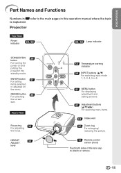
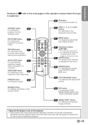
... topic is explained. Front View Focus ring 30 For adjusting the focus. ENTER button 41 For setting items selected or adjusted on and putting the projector into standby mode. HEIGHT 30 ADJUST lever 52 Temperature warning indicator 29 INPUT buttons (P/R) For switching input mode 1, 2, 3, 4, 5 or 6. 41 MENU button For displaying... picture. 15 Remote control sensor (front) Push both sides of the lens cap to the main pages in Z refer to attach or remove. 11 Projector Top View Power indicator 28, 52 28, 52 Lamp indicator STANDBY/ON 28 button For turning the power on the menu.
... topic is explained. Front View Focus ring 30 For adjusting the focus. ENTER button 41 For setting items selected or adjusted on and putting the projector into standby mode. HEIGHT 30 ADJUST lever 52 Temperature warning indicator 29 INPUT buttons (P/R) For switching input mode 1, 2, 3, 4, 5 or 6. 41 MENU button For displaying... picture. 15 Remote control sensor (front) Push both sides of the lens cap to the main pages in Z refer to attach or remove. 11 Projector Top View Power indicator 28, 52 28, 52 Lamp indicator STANDBY/ON 28 button For turning the power on the menu.
DT-500 Operation Manual
Page 14
... topic is explained. 28 ON button For turning the power on how to use with the system for use it to secure the projector. 13 RETURN button 41 For returning to the respective input signal type. RGB/COMP. Using the Kensington Lock on the... projector • This projector has a Kensington Security Standard connector for instructions on . STANDBY button 29 For putting the projector into the standby mode. AUTO SYNC button 46 For automatically adjusting images when connected to the ...
... topic is explained. 28 ON button For turning the power on how to use with the system for use it to secure the projector. 13 RETURN button 41 For returning to the respective input signal type. RGB/COMP. Using the Kensington Lock on the... projector • This projector has a Kensington Security Standard connector for instructions on . STANDBY button 29 For putting the projector into the standby mode. AUTO SYNC button 46 For automatically adjusting images when connected to the ...

DT-500 Operation Manual
Page 15
... • Danger of explosion if battery is harmful to skin, therefore ensure that you will not be using a cloth. • The batteries included with this projector may cause them using the remote control for a long time. • Comply with the rules (ordinance) of each local government when disposing of worn-out...
... • Danger of explosion if battery is harmful to skin, therefore ensure that you will not be using a cloth. • The batteries included with this projector may cause them using the remote control for a long time. • Comply with the rules (ordinance) of each local government when disposing of worn-out...

DT-500 Operation Manual
Page 16
... distance of the signal may malfunction under a fluorescent lamp. When using the remote control • Ensure that you do not drop, expose to control the projector within the ranges shown in the illustration. Remote control sensor (front) 30° Remote control signal transmitters 30° 23n (7 m) Remote control Remote control sensor...
... distance of the signal may malfunction under a fluorescent lamp. When using the remote control • Ensure that you do not drop, expose to control the projector within the ranges shown in the illustration. Remote control sensor (front) 30° Remote control signal transmitters 30° 23n (7 m) Remote control Remote control sensor...
DT-500 Operation Manual
Page 17
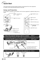
... a wall or a screen _P. 18 2. Connect the projector to the video equipment and plug the power cord into the AC socket of the projector _PP. 22-28 To INPUT 4 terminal AC socket Connect the audio output of the projector and the video equipment is explained using one ex- Quick Start This ...section shows the basic operation (projector connecting with the video equipment). ample. 3 STANDBY/ON 8 button 8 STANDBY button 5 INPUT buttons 3 ON button 5 INPUT 4 button 7 KEYSTONE button 6 Focus ring 6 Zoom ring 6 HEIGHT ...
... a wall or a screen _P. 18 2. Connect the projector to the video equipment and plug the power cord into the AC socket of the projector _PP. 22-28 To INPUT 4 terminal AC socket Connect the audio output of the projector and the video equipment is explained using one ex- Quick Start This ...section shows the basic operation (projector connecting with the video equipment). ample. 3 STANDBY/ON 8 button 8 STANDBY button 5 INPUT buttons 3 ON button 5 INPUT 4 button 7 KEYSTONE button 6 Focus ring 6 Zoom ring 6 HEIGHT ...

DT-500 Operation Manual
Page 18
...the remote control to set the upper-right, lower-right, and lower-left position of the projected image. • When you to put the projector into standby mode. Press P/R/O/Q on the remote control also allows you confirm the lower left position, the screen adjustments will end. 8. On ...the On the remote projector control On-screen Display • Unplug the power cord from the AC outlet after the cooling fan stops. 17 Adjust the projection image size...
...the remote control to set the upper-right, lower-right, and lower-left position of the projected image. • When you to put the projector into standby mode. Press P/R/O/Q on the remote control also allows you confirm the lower left position, the screen adjustments will end. 8. On ...the On the remote projector control On-screen Display • Unplug the power cord from the AC outlet after the cooling fan stops. 17 Adjust the projection image size...
DT-500 Operation Manual
Page 19
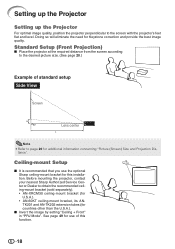
Doing so will eliminate the need for countries other than the U.S.A.). tance". Before mounting the projector, contact your nearest Sharp Authorized Service Center or Dealer to obtain the recommended ceiling-mount bracket (sold separately). • AN-XRCM30 ceiling-mount ... tubes (for Keystone correction and provide the best image quality. Setting up the Projector Setting up the Projector For optimal image quality, position the projector perpendicular to page 20 for use the optional Sharp ceiling-mount bracket for this function. 18 Standard Setup (Front Projection) I Place...
Doing so will eliminate the need for countries other than the U.S.A.). tance". Before mounting the projector, contact your nearest Sharp Authorized Service Center or Dealer to obtain the recommended ceiling-mount bracket (sold separately). • AN-XRCM30 ceiling-mount ... tubes (for Keystone correction and provide the best image quality. Setting up the Projector Setting up the Projector For optimal image quality, position the projector perpendicular to page 20 for use the optional Sharp ceiling-mount bracket for this function. 18 Standard Setup (Front Projection) I Place...

DT-500 Operation Manual
Page 20
..." 5'1(11."8-6m'1-127".1'1m(12)."4-9m'2-"2.89m'1) (13."0-1m1-'63".5 m1)9'(16.00"m-2-27'1.012m"9)'(99."1-3m4-'51"0.5 m) Projection Distance 19 Projection (PRJ) Mode The projector can use . (You can set the PRJ Mode in the diagram below.
..." 5'1(11."8-6m'1-127".1'1m(12)."4-9m'2-"2.89m'1) (13."0-1m1-'63".5 m1)9'(16.00"m-2-27'1.012m"9)'(99."1-3m4-'51"0.5 m) Projection Distance 19 Projection (PRJ) Mode The projector can use . (You can set the PRJ Mode in the diagram below.

DT-500 Operation Manual
Page 21
...projection distance (ft/m) H: Distance from the lens center to the bottom of the image (in/cm) S: Adjustable range of the projector to the screen. Setting up the Projector (Continued) Picture (Screen) Size and Projection Distance The projection screen size varies according to the distance from the lens of image ...position (in/cm) See page 47. Install the projector so that projected images are projected onto the screen at the optimum size by referring to the table below. The formula for picture size...
...projection distance (ft/m) H: Distance from the lens center to the bottom of the image (in/cm) S: Adjustable range of the projector to the screen. Setting up the Projector (Continued) Picture (Screen) Size and Projection Distance The projection screen size varies according to the distance from the lens of image ...position (in/cm) See page 47. Install the projector so that projected images are projected onto the screen at the optimum size by referring to the table below. The formula for picture size...

DT-500 Operation Manual
Page 23
..., 2 INPUT5 INPUT3 Video cable (commercially available) Video INPUT4 Camera/ video game Cables for a camera or a video game Compo- Equipment Input Signal Cable Terminal on the projector Audio-visual equipment HDMI video HDMI cable (commercially available) INPUT6 Component video Component cable (commercially available) Component video 3 RCA to 15-pin D-sub INPUT5 Cables...
..., 2 INPUT5 INPUT3 Video cable (commercially available) Video INPUT4 Camera/ video game Cables for a camera or a video game Compo- Equipment Input Signal Cable Terminal on the projector Audio-visual equipment HDMI video HDMI cable (commercially available) INPUT6 Component video Component cable (commercially available) Component video 3 RCA to 15-pin D-sub INPUT5 Cables...

DT-500 Operation Manual
Page 24
Connecting to Video Equipment Before connecting, ensure that the power cord of the projector is unplugged from the AC outlet and turn on the projector (INPUT1 or INPUT2) To component output (Y, CB/PB, CR/PR) terminal DVD, etc. When connecting the component video equipment to be connected. To INPUT1 or INPUT2 terminal Component cable (commercially available) Connections 23 After making all connections, turn off the devices to the component input terminal on the projector first and then the other devices.
Connecting to Video Equipment Before connecting, ensure that the power cord of the projector is unplugged from the AC outlet and turn on the projector (INPUT1 or INPUT2) To component output (Y, CB/PB, CR/PR) terminal DVD, etc. When connecting the component video equipment to be connected. To INPUT1 or INPUT2 terminal Component cable (commercially available) Connections 23 After making all connections, turn off the devices to the component input terminal on the projector first and then the other devices.

DT-500 Operation Manual
Page 26
Connections When connecting the component video equipment to 15-pin D-sub cable (optional accessory: AN-C3CP2) 25 To INPUT5 terminal 3 RCA to the computer-RGB/ component input terminal on the projector (INPUT5) To component output (Y, CB/PB, CR/PR) terminal DVD, etc.
Connections When connecting the component video equipment to 15-pin D-sub cable (optional accessory: AN-C3CP2) 25 To INPUT5 terminal 3 RCA to the computer-RGB/ component input terminal on the projector (INPUT5) To component output (Y, CB/PB, CR/PR) terminal DVD, etc.

DT-500 Operation Manual
Page 27
... that do not conform to HDMI standards may result in just one cable. For video connection, use an amplifier or other audio device. Since this projector does not support an audio signal by itself, use a cable that conforms to HDMI standards. tion video signal, multi-channel audio signal, and bi-directional...
... that do not conform to HDMI standards may result in just one cable. For video connection, use an amplifier or other audio device. Since this projector does not support an audio signal by itself, use a cable that conforms to HDMI standards. tion video signal, multi-channel audio signal, and bi-directional...
DT-500 Operation Manual
Page 29
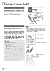
...screen display to another language, change the language according to 28.) Remove the lens cap and press S STANDBY/ON on the projector or bON on the projector, a slight flickering of the lamp. Lamp indicator Power indicator Note • About the Lamp Indicator The lamp indicator illuminates to... turned on . Info • English is stabilising the lamp output characteristics. This is normal operation as faulty operation. • If the projector is shut down . It should not be experienced within the first minute after the lamp has been illuminated. Green: The lamp is warming...
...screen display to another language, change the language according to 28.) Remove the lens cap and press S STANDBY/ON on the projector or bON on the projector, a slight flickering of the lamp. Lamp indicator Power indicator Note • About the Lamp Indicator The lamp indicator illuminates to... turned on . Info • English is stabilising the lamp output characteristics. This is normal operation as faulty operation. • If the projector is shut down . It should not be experienced within the first minute after the lamp has been illuminated. Green: The lamp is warming...


