CV-10NH Operation Manual
Page 3
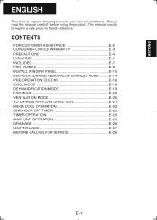
... your new air conditioner. This manual should be kept in a safe place for handy reference. CONTENTS • FOR CUSTOMER ASSISTANCE E-2 • CONSUMER LIMITED WARRANTY E-3 • PRECAUTIONS E-4 • LOCATION E-7 • INCLUDED E-7 • PART NAMES E-8 • INSTALL WINDOW PANEL E-10 • INSTALLATION AND REMOVAL OF EXHAUST HOSE .........E-14 • PRE-OPERATION CHECKS E-16 • COOL MODE...
... your new air conditioner. This manual should be kept in a safe place for handy reference. CONTENTS • FOR CUSTOMER ASSISTANCE E-2 • CONSUMER LIMITED WARRANTY E-3 • PRECAUTIONS E-4 • LOCATION E-7 • INCLUDED E-7 • PART NAMES E-8 • INSTALL WINDOW PANEL E-10 • INSTALLATION AND REMOVAL OF EXHAUST HOSE .........E-14 • PRE-OPERATION CHECKS E-16 • COOL MODE...
CV-10NH Operation Manual
Page 5
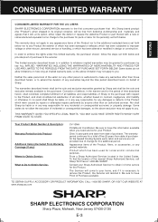
...the seller nor any other person is authorized to make any warranties other than those described herein, or to Obtain Service: CV-10NH Portable Air Conditioner. THIS WARRANTY GIVES YOU SPECIFlC LEGAL RIGHTS. One (1) year parts and labor from date of any printed materials. Product which has ... total of five (5) years from date of defects, in -home service for the Sealed Cooling System parts; From a Sharp Authorized Servicer located in design or construction. Contact your Sharp Authorized Servicer to obtain in the manner and for your home, and if it is in the Product...
...the seller nor any other person is authorized to make any warranties other than those described herein, or to Obtain Service: CV-10NH Portable Air Conditioner. THIS WARRANTY GIVES YOU SPECIFlC LEGAL RIGHTS. One (1) year parts and labor from date of any printed materials. Product which has ... total of five (5) years from date of defects, in -home service for the Sealed Cooling System parts; From a Sharp Authorized Servicer located in design or construction. Contact your Sharp Authorized Servicer to obtain in the manner and for your home, and if it is in the Product...
CV-10NH Operation Manual
Page 7
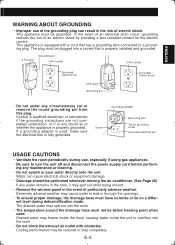
... is properly grounded. Extremely adverse weather may cause water to leak in any circumstances cut or remove the round grounding pin from this plug. Cooling performance may spill out while being moved. • Remove the window panel in the risk of particularly adverse weather. Consult a qualifi...ow into the room. • The temperature around the drainage hose must be on a differ- The plug must not be performed whenever moving the air conditioner. (See Page 26) If any maintenance or cleaning. • Do not splash or pour water directly onto the unit. Water can result in...
... is properly grounded. Extremely adverse weather may cause water to leak in any circumstances cut or remove the round grounding pin from this plug. Cooling performance may spill out while being moved. • Remove the window panel in the risk of particularly adverse weather. Consult a qualifi...ow into the room. • The temperature around the drainage hose must be on a differ- The plug must not be performed whenever moving the air conditioner. (See Page 26) If any maintenance or cleaning. • Do not splash or pour water directly onto the unit. Water can result in...
CV-10NH Operation Manual
Page 8
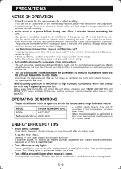
...Turn off for three minutes for safety. • In the event of air as that are not in cooling mode. • Keep the filter clean. The less time the air conditioner is reinstated, restart the air conditioner. This protective device will be sure to freeze. There is an electronic device... tank inside the unit is home. Warm air will prevent cooling for the compressor to shut off the air conditioner when no one is full, the unit stops operating and TIMER, OPERATION and MEGA COOL lamps will rise. If you restart the air conditioner within the unit. (See page 26) ...
...Turn off for three minutes for safety. • In the event of air as that are not in cooling mode. • Keep the filter clean. The less time the air conditioner is reinstated, restart the air conditioner. This protective device will be sure to freeze. There is an electronic device... tank inside the unit is home. Warm air will prevent cooling for the compressor to shut off the air conditioner when no one is full, the unit stops operating and TIMER, OPERATION and MEGA COOL lamps will rise. If you restart the air conditioner within the unit. (See page 26) ...
CV-10NH Operation Manual
Page 10
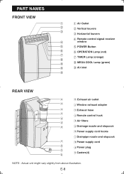
... louvers 3 3 Horizontal louvers 4 Remote control signal receiver 4 window 5 5 POWER Button 6 6 OPERATION Lamp (red) 7 7 TIMER Lamp (orange) 8 9 8 MEGA COOL Lamp (green) 9 9 Air inlet 9 REAR VIEW 0 0 Exhaust air outlet q q Window exhaust adapter w w Exhaust hose e e Remote control hook r t r Air filters y t Drainage nozzle and stopcock y Power supply cord hooks u Drainpipe nozzle and stopcock u i Power supply cord i o Power...
... louvers 3 3 Horizontal louvers 4 Remote control signal receiver 4 window 5 5 POWER Button 6 6 OPERATION Lamp (red) 7 7 TIMER Lamp (orange) 8 9 8 MEGA COOL Lamp (green) 9 9 Air inlet 9 REAR VIEW 0 0 Exhaust air outlet q q Window exhaust adapter w w Exhaust hose e e Remote control hook r t r Air filters y t Drainage nozzle and stopcock y Power supply cord hooks u Drainpipe nozzle and stopcock u i Power supply cord i o Power...
CV-10NH Operation Manual
Page 11
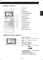
ENGLISH REMOTE CONTROL 1 2 3 4 5 6 7 8 9 0 q w e 1 Transmitter 2 Display 3 POWER Button 4 TEMPERATURE Button 5 1 hr OFF Button 6 MODE Button 7 ON TIMER Button 8 FAN Button 9 OFF TIMER Button 0 CANCEL Button q LOUVERS Button w RESET Button e MEGA COOL Button REMOTE CONTROL DISPLAY r r MODE SYMBOLS : COOL : DEHUMIDIFICATION t u : FAN : VENTILATION i t MEGA COOL SYMBOL y FAN SPEED SYMBOLS y o : AUTO Quiet : Manual setting Low High u TEMPERATURE AND TIMER COUNT DOWN INDICATOR i TRANSMITTING SYMBOL o ON TIMER / OFF TIMER SYMBOL E-9
ENGLISH REMOTE CONTROL 1 2 3 4 5 6 7 8 9 0 q w e 1 Transmitter 2 Display 3 POWER Button 4 TEMPERATURE Button 5 1 hr OFF Button 6 MODE Button 7 ON TIMER Button 8 FAN Button 9 OFF TIMER Button 0 CANCEL Button q LOUVERS Button w RESET Button e MEGA COOL Button REMOTE CONTROL DISPLAY r r MODE SYMBOLS : COOL : DEHUMIDIFICATION t u : FAN : VENTILATION i t MEGA COOL SYMBOL y FAN SPEED SYMBOLS y o : AUTO Quiet : Manual setting Low High u TEMPERATURE AND TIMER COUNT DOWN INDICATOR i TRANSMITTING SYMBOL o ON TIMER / OFF TIMER SYMBOL E-9
CV-10NH Operation Manual
Page 16
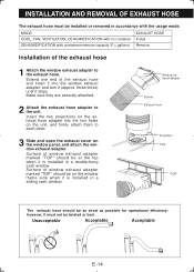
... turn it stops. INSTALLATION AND REMOVAL OF EXHAUST HOSE The exhaust hose must not be twisted or bent. Unacceptable Acceptable Acceptable E-14 MODE EXHAUST HOSE COOL, FAN, VENTILATION, DEHUMIDIFICATION with no container Install DEHUMIDIFICATION with the usage mode. Window exhaust adapter Extend Exhaust hose Projection Hole "TOP" The exhaust hose should...
... turn it stops. INSTALLATION AND REMOVAL OF EXHAUST HOSE The exhaust hose must not be twisted or bent. Unacceptable Acceptable Acceptable E-14 MODE EXHAUST HOSE COOL, FAN, VENTILATION, DEHUMIDIFICATION with no container Install DEHUMIDIFICATION with the usage mode. Window exhaust adapter Extend Exhaust hose Projection Hole "TOP" The exhaust hose should...
CV-10NH Operation Manual
Page 20
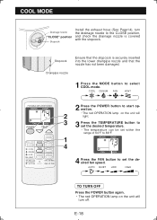
...securely inserted into the lower drainpipe nozzle and that the nozzle has not been damaged. 1 Press the MODE button to set the desired fan speed. COOL DEHUM FAN VENT 2 Press the POWER button to start operation. 2 • The red OPERATION lamp on the unit will light. 3 3 ...temperature can be set within the range of 64°F to 86°F. 1 4 4 Press the FAN button to select COOL mode. Stopcock Drainpipe nozzle Ensure that the stopcock is covered with the stopcock. E-18 COOL MODE Drainage nozzle "CLOSE" position Stopcock Install the exhaust hose (See Page14), turn off.
...securely inserted into the lower drainpipe nozzle and that the nozzle has not been damaged. 1 Press the MODE button to set the desired fan speed. COOL DEHUM FAN VENT 2 Press the POWER button to start operation. 2 • The red OPERATION lamp on the unit will light. 3 3 ...temperature can be set within the range of 64°F to 86°F. 1 4 4 Press the FAN button to select COOL mode. Stopcock Drainpipe nozzle Ensure that the stopcock is covered with the stopcock. E-18 COOL MODE Drainage nozzle "CLOSE" position Stopcock Install the exhaust hose (See Page14), turn off.
CV-10NH Operation Manual
Page 21
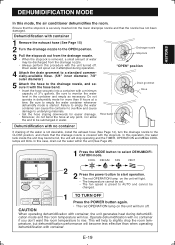
... Stopcock "OPEN" position 4 Attach the drain grommet to a standard commercially-available hose. (5/8" inner diameter, 7/8" outer diameter) 5 Attach the hose to be submerged in water. COOL DEHUM FAN VENT 2 2 Press the power button to the CLOSE position, and check that the drainage nozzle is started. CAUTION When operating dehumidification... mode for easier drainage. Be sure to the OPEN position. 3 Pull the stopcock out from the drainage nozzle. • Always perform this mode, the air conditioner dehumidifies the room. Moreover, do not bend the hose at a time.
... Stopcock "OPEN" position 4 Attach the drain grommet to a standard commercially-available hose. (5/8" inner diameter, 7/8" outer diameter) 5 Attach the hose to be submerged in water. COOL DEHUM FAN VENT 2 2 Press the power button to the CLOSE position, and check that the drainage nozzle is started. CAUTION When operating dehumidification... mode for easier drainage. Be sure to the OPEN position. 3 Pull the stopcock out from the drainage nozzle. • Always perform this mode, the air conditioner dehumidifies the room. Moreover, do not bend the hose at a time.
CV-10NH Operation Manual
Page 22
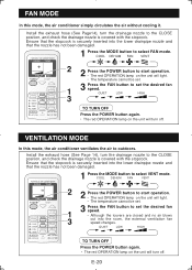
E-20 VENTILATION MODE In this mode, the air conditioner simply circulates the air without cooling it. Install the exhaust hose (See Page 14), turn .... • The temperature cannot be set. 1 3 Press the FAN button to set the desired fan speed. COOL DEHUM FAN VENT 2 2 Press the POWER button to start operation. • The red OPERATION lamp on the...been damaged. 1 Press the MODE button to select VENT mode. FAN MODE In this mode, the air conditioner ventilates the air to outdoors. Install the exhaust hose (See Page14), turn off . Ensure that the nozzle has not...
E-20 VENTILATION MODE In this mode, the air conditioner simply circulates the air without cooling it. Install the exhaust hose (See Page 14), turn .... • The temperature cannot be set. 1 3 Press the FAN button to set the desired fan speed. COOL DEHUM FAN VENT 2 2 Press the POWER button to start operation. • The red OPERATION lamp on the...been damaged. 1 Press the MODE button to select VENT mode. FAN MODE In this mode, the air conditioner ventilates the air to outdoors. Install the exhaust hose (See Page14), turn off . Ensure that the nozzle has not...
CV-10NH Operation Manual
Page 23
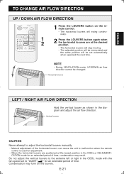
... with the fan speed set automatically when operated the next time. E-21 Horizontal louvers LEFT / RIGHT AIR FLOW DIRECTION Hold the vertical louver as shown in the COOL or DEHUMIDIFI- Vertical louvers CAUTION Never attempt to adjust the horizontal louvers manually. • Manual adjustment of ...time. NOTE • During VENTILATION mode, UP/DOWN air flow direction cannot be set to malfunction...
... with the fan speed set automatically when operated the next time. E-21 Horizontal louvers LEFT / RIGHT AIR FLOW DIRECTION Hold the vertical louver as shown in the COOL or DEHUMIDIFI- Vertical louvers CAUTION Never attempt to adjust the horizontal louvers manually. • Manual adjustment of ...time. NOTE • During VENTILATION mode, UP/DOWN air flow direction cannot be set to malfunction...
CV-10NH Operation Manual
Page 24
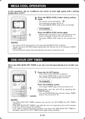
...when the mode is changed, or when the unit is turned off. • The green MEGA COOL lamp on the unit will turn off after one hour. MEGA COOL OPERATION In this operation, the air conditioner fan works at the formerly set condition. • If you wish to operate the unit for another... hour before the ONE-HOUR OFF TIMER is set the temperature or fan speed during MEGA COOL operation. • The fan returns...
...when the mode is changed, or when the unit is turned off. • The green MEGA COOL lamp on the unit will turn off after one hour. MEGA COOL OPERATION In this operation, the air conditioner fan works at the formerly set condition. • If you wish to operate the unit for another... hour before the ONE-HOUR OFF TIMER is set the temperature or fan speed during MEGA COOL operation. • The fan returns...
CV-10NH Operation Manual
Page 27
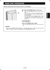
... remote control is not available. 1 Press the POWER button on the unit. • The red OPERATION lamp on the unit will resume operation in the cooling mode, set to AUTO.
... remote control is not available. 1 Press the POWER button on the unit. • The red OPERATION lamp on the unit will resume operation in the cooling mode, set to AUTO.
CV-10NH Operation Manual
Page 28
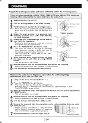
... drain water will take about one minute. 8 Remove the hose from spilling). Whenever the unit is approximately 41/5 pints. • The OPERATION, TIMER and MEGA COOL lamps will drain out through the drainage hose. Drainage nozzle 3 Pull the stopcock out from the drainage nozzle. • When the stopcock is removed, a small... unit in case of re-used. 9 Turn the drainage nozzle to the OPEN position. If the unit stops operating and the TIMER, OPERATION and MEGA COOL lamps are blinking. (This indicates that may be drained out is moved (to the drainpipe nozzle.
... drain water will take about one minute. 8 Remove the hose from spilling). Whenever the unit is approximately 41/5 pints. • The OPERATION, TIMER and MEGA COOL lamps will drain out through the drainage hose. Drainage nozzle 3 Pull the stopcock out from the drainage nozzle. • When the stopcock is removed, a small... unit in case of re-used. 9 Turn the drainage nozzle to the OPEN position. If the unit stops operating and the TIMER, OPERATION and MEGA COOL lamps are blinking. (This indicates that may be drained out is moved (to the drainpipe nozzle.
CV-10NH Operation Manual
Page 29
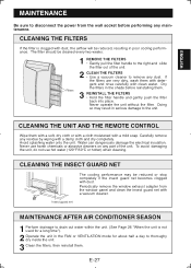
...adapter from the wall socket before reinstalling them with a soft, dry cloth or with a cloth moistened with dust. Insect guard net MAINTENANCE AFTER AIR CONDITIONER SEASON 1 Perform drainage to drain out water within the unit. (See Page 26 "When the unit is clogged with clean water. CLEANING ... REINSTALL THE FILTERS • Hold the filter handle and gently push the filter back into place. CLEANING THE INSECT GUARD NET The cooling performance may result in the shade before performing any part of the unit. 2 CLEAN THE FILTERS • Use a vacuum cleaner to thoroughy dry...
...adapter from the wall socket before reinstalling them with a soft, dry cloth or with a cloth moistened with dust. Insect guard net MAINTENANCE AFTER AIR CONDITIONER SEASON 1 Perform drainage to drain out water within the unit. (See Page 26 "When the unit is clogged with clean water. CLEANING ... REINSTALL THE FILTERS • Hold the filter handle and gently push the filter back into place. CLEANING THE INSECT GUARD NET The cooling performance may result in the shade before performing any part of the unit. 2 CLEAN THE FILTERS • Use a vacuum cleaner to thoroughy dry...
CV-10NH Operation Manual
Page 30
...;cient operation, make the hose as short as possible. If the power was off , and also during cooling operation within 3 minutes of the compressor starting AUXILIARY mode. Run the air conditioner in the remote control. THE UNIT FAILS TO REACT TO THE REMOTE CONTROL SIGNAL • Check the batteries... hose must be drained. (See page26) • Check the power plug. (See page16) AIR CONDITIONER DOES NOT COOL PROPERLY • Is it set , the TIMER setting will be cancelled and will blow out if the cooling coil is the sound of a power failure? Place the unit on a gently sloping fl...
...;cient operation, make the hose as short as possible. If the power was off , and also during cooling operation within 3 minutes of the compressor starting AUXILIARY mode. Run the air conditioner in the remote control. THE UNIT FAILS TO REACT TO THE REMOTE CONTROL SIGNAL • Check the batteries... hose must be drained. (See page26) • Check the power plug. (See page16) AIR CONDITIONER DOES NOT COOL PROPERLY • Is it set , the TIMER setting will be cancelled and will blow out if the cooling coil is the sound of a power failure? Place the unit on a gently sloping fl...


