

Service Manual
Page 11
...Tape 1 Cassette Compartment 11. Game/Video Input Jacks 5 13. Memory/Set Button 8 18. CD or Tape Stop Button 20. CD Pause Indicator 4. Daily Timer Indicator 11. FM Stereo Receiving Indicator 12. Cooling Fan 2. FM 75 Ohms Antenna Terminal 4. FM Antenna Ground Terminal ... Number Indicators 2. Sleep Indicator 14. Video Output Jack 7. Equalizer Mode Select Button 4 10. FM Stereo Mode Indicator 10. Extra Bass Indicator 8. CD Indicator 7. Tape Play Indicator 9. Timer Recording Indicator Rear panel 1. Clock/Timer Button 6. Headphone Jack 12. Disc ...
...Tape 1 Cassette Compartment 11. Game/Video Input Jacks 5 13. Memory/Set Button 8 18. CD or Tape Stop Button 20. CD Pause Indicator 4. Daily Timer Indicator 11. FM Stereo Receiving Indicator 12. Cooling Fan 2. FM 75 Ohms Antenna Terminal 4. FM Antenna Ground Terminal ... Number Indicators 2. Sleep Indicator 14. Video Output Jack 7. Equalizer Mode Select Button 4 10. FM Stereo Mode Indicator 10. Extra Bass Indicator 8. CD Indicator 7. Tape Play Indicator 9. Timer Recording Indicator Rear panel 1. Clock/Timer Button 6. Headphone Jack 12. Disc ...
Service Manual
Page 14
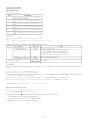
... version number will only be displayed when error had been detected for 10 secs. Display will be displayed instead of Stereo System Error Message Display Contents Error Contents CD Pickup Mechanism Error. Press OPEN/CLOSE button until "WAIT" o "FINISHED" appears. 4. Unplug the AC cord and... the unit is condition when irregular process occur on power supply line. CD-ES900/CD-ES99 [3] CD section CD Error code description Error 01 10* 11* 20* 21* 31 Explanation When Pickup set tapering/parts replacement. 1. When it change ...
... version number will only be displayed when error had been detected for 10 secs. Display will be displayed instead of Stereo System Error Message Display Contents Error Contents CD Pickup Mechanism Error. Press OPEN/CLOSE button until "WAIT" o "FINISHED" appears. 4. Unplug the AC cord and... the unit is condition when irregular process occur on power supply line. CD-ES900/CD-ES99 [3] CD section CD Error code description Error 01 10* 11* 20* 21* 31 Explanation When Pickup set tapering/parts replacement. 1. When it change ...

Service Manual
Page 54
... IXA002AW (Serial No. 31000001~402XXXXX) IXA007AW (Serial No. 402XXXXX) IXA020AW (Serial No. 402XXXXX~) SYSTEM Figure 4-2 BLOCK DIAGRAM (2/3) 4 - 2 HEAD REC. HEAD R-CH TAPE 2 REC./P.B. CD-ES900/CD-ES99 +B4 FM ANTENNA IC301 TA7358AP ZD351 5.1V FM FRONT END FM IF 10.7 MHz BF301 1 6 SO302 B.P.F 9 34 5 7 8 FM OSC FM ANTENNA TERMINAL FM RF...FM/AM MO/ST FM DET MPXIN FM/AM GND OUT FM+B AM IF AM MIX L 14 R 15 24 23 21 7 18 16 12 STEREO AM OSC OUT AM OSC IN AM RF IN 1 OSC BUFF 2 CNP301 Q302 AM TRACKING T303 T306 AM BAND COVERAGE VT X352 4.5 MHz IC303 LA1832S...
... IXA002AW (Serial No. 31000001~402XXXXX) IXA007AW (Serial No. 402XXXXX) IXA020AW (Serial No. 402XXXXX~) SYSTEM Figure 4-2 BLOCK DIAGRAM (2/3) 4 - 2 HEAD REC. HEAD R-CH TAPE 2 REC./P.B. CD-ES900/CD-ES99 +B4 FM ANTENNA IC301 TA7358AP ZD351 5.1V FM FRONT END FM IF 10.7 MHz BF301 1 6 SO302 B.P.F 9 34 5 7 8 FM OSC FM ANTENNA TERMINAL FM RF...FM/AM MO/ST FM DET MPXIN FM/AM GND OUT FM+B AM IF AM MIX L 14 R 15 24 23 21 7 18 16 12 STEREO AM OSC OUT AM OSC IN AM RF IN 1 OSC BUFF 2 CNP301 Q302 AM TRACKING T303 T306 AM BAND COVERAGE VT X352 4.5 MHz IC303 LA1832S...
Service Manual
Page 56
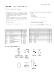
...Mylar type (P.P.): Polypropylene type • Schematic diagram and Wiring Side of P.W.Board for maintaining the safety and performance of the set . In the CD section, the CD is stopped. • Parts marked with " " ( ) are subject to replace these parts with specified ones for this symbol P means ...TOP VIEW 1N4004S TOP VIEW KDS184 FRONT VIEW AC AC D10XB60F 5 - 1 FRONT VIEW 304VT2H3 SDPB50CD In the tuner section, indicates AM indicates FM stereo 2. In the power section, a tape is the one with no signal given. 1. REF NO. Besides, the one measured by Digital Multimeter ...
...Mylar type (P.P.): Polypropylene type • Schematic diagram and Wiring Side of P.W.Board for maintaining the safety and performance of the set . In the CD section, the CD is stopped. • Parts marked with " " ( ) are subject to replace these parts with specified ones for this symbol P means ...TOP VIEW 1N4004S TOP VIEW KDS184 FRONT VIEW AC AC D10XB60F 5 - 1 FRONT VIEW 304VT2H3 SDPB50CD In the tuner section, indicates AM indicates FM stereo 2. In the power section, a tape is the one with no signal given. 1. REF NO. Besides, the one measured by Digital Multimeter ...

Service Manual
Page 69
....7 MHz C398 100/10 R388 3.9K C355 22P(CH) C370 1/50 C357 R355 2.2/50 3.3K C356 0.001 R353 270 12 C358 1/50 10 11 9 78 STEREO FM DET VCC MPX VCO MPX IN IF OUT PHASE R-CH OUT L-CH OUT PHASE (FM/AM) MO/ST 17 16 X351 456 kHz C368... 0.015 C373 0.015 C372 1/50 15 14 13 C371 1/50 IC303 LA1832S FM IF DET./FM MPX./AM IF TP302 TP FM SIGNAL AM SIGNAL CD-ES900/CD-ES99
....7 MHz C398 100/10 R388 3.9K C355 22P(CH) C370 1/50 C357 R355 2.2/50 3.3K C356 0.001 R353 270 12 C358 1/50 10 11 9 78 STEREO FM DET VCC MPX VCO MPX IN IF OUT PHASE R-CH OUT L-CH OUT PHASE (FM/AM) MO/ST 17 16 X351 456 kHz C368... 0.015 C373 0.015 C372 1/50 15 14 13 C371 1/50 IC303 LA1832S FM IF DET./FM MPX./AM IF TP302 TP FM SIGNAL AM SIGNAL CD-ES900/CD-ES99


