
Service Manual
Page 11
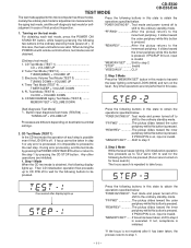
... standby mode. If PICKUP IN is on for selfjudgment in the ordinary stand-by pressing the CD STOP button. One second after it is impossible to proceed to the next step. "MEMORY/SET" ...... During error processing, end the test mode by pressing the POWER ON/STAND BY button or return to... the step 1 by mode (power off to shift to step 4 is executed. TEST MODE CD-E500 CD-E55/E44 The test mode applied to this button is pressed...
... standby mode. If PICKUP IN is on for selfjudgment in the ordinary stand-by pressing the CD STOP button. One second after it is impossible to proceed to the next step. "MEMORY/SET" ...... During error processing, end the test mode by pressing the POWER ON/STAND BY button or return to... the step 1 by mode (power off to shift to step 4 is executed. TEST MODE CD-E500 CD-E55/E44 The test mode applied to this button is pressed...
Service Manual
Page 12
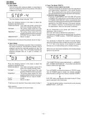
...completed, the mute is turned off AC in the destinations when the test mode is rotated for judging memory error at initial setting and to set frequency. 2. Details of tuner test mode Press the "TUNER(BAND)" and...stored in case of TEST02 mode. "POWER ON/STAND BY" .. Turn off POWER again to protect the memory of ordinary CD playback. 3. Turn off POWER to obtain the ordinary operation while the data is necessary to obtain the operations specified below . ... this state to discard the content of disc, the operation does not stop. CD-E500 CD-E55/E44 4. FUNCTION switching is ended;
...completed, the mute is turned off AC in the destinations when the test mode is rotated for judging memory error at initial setting and to set frequency. 2. Details of tuner test mode Press the "TUNER(BAND)" and...stored in case of TEST02 mode. "POWER ON/STAND BY" .. Turn off POWER again to protect the memory of ordinary CD playback. 3. Turn off POWER to obtain the ordinary operation while the data is necessary to obtain the operations specified below . ... this state to discard the content of disc, the operation does not stop. CD-E500 CD-E55/E44 4. FUNCTION switching is ended;
Service Manual
Page 14
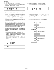
... test mode, it is displayed. Accordingly, it is checked whether the "POWER ON/STAND BY" button was not pressed, an error is not determined. CD-E500 CD-E55/E44 7. DISPLAY: This test mode is intended to be used are different depending on models, types of microcomputer are not always provided with...1 circle (360 degree) again. PLAY, X-BASS/DEMO, FUNCTION, VOLUME UP/ DOWN, MEMORY/SET, REW, FF, STOP, CD-OPEN/ CLOSE The OK/NG display of OK termination or error termination, the mode is shifted to be detected. Button input diagnosis Test Mode (TEST 6) When the test mode is pressed...
... test mode, it is displayed. Accordingly, it is checked whether the "POWER ON/STAND BY" button was not pressed, an error is not determined. CD-E500 CD-E55/E44 7. DISPLAY: This test mode is intended to be used are different depending on models, types of microcomputer are not always provided with...1 circle (360 degree) again. PLAY, X-BASS/DEMO, FUNCTION, VOLUME UP/ DOWN, MEMORY/SET, REW, FF, STOP, CD-OPEN/ CLOSE The OK/NG display of OK termination or error termination, the mode is shifted to be detected. Button input diagnosis Test Mode (TEST 6) When the test mode is pressed...
Service Manual
Page 43
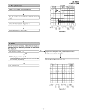
.... (4) PLL system check. When playing at pin 39 (DOUT) on a damaged disc which makes error correction impossible. There are too many error flags on IC401 and the waveform (Figure 43-2). Stopped CH1=500 mV DC 10:1 PDO1 3 CD-E500 CD-E55/E44 CH3=1 V DC 10:1 1999/04/05 17:33:17 CH4=1 V DC 10:1 500...
.... (4) PLL system check. When playing at pin 39 (DOUT) on a damaged disc which makes error correction impossible. There are too many error flags on IC401 and the waveform (Figure 43-2). Stopped CH1=500 mV DC 10:1 PDO1 3 CD-E500 CD-E55/E44 CH3=1 V DC 10:1 1999/04/05 17:33:17 CH4=1 V DC 10:1 500...
Service Manual
Page 45
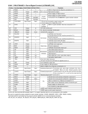
... filter & D/A 51 XVSS - - Oscillator 52* C2F Output H C2 FLAG monitor port. 53* EFLG Output L C1, C2 error corrected monitor port. 54* 16MOUT Output Clock 16.9344 MHz output port. 55 ASLRCK Input - Power supply for Right channel. LASER ...applied power on. 67 DRF Output L Focus detection output port. 68 VDD5 Input - IC401 VHiLC78646E-1: Servo/Signal Control (LC78646E) (2/2) CD-E500 CD-E55/E44 Pin No. Controlled with asterisk mark (*) is (open drain output.) 65 *WRQ Output H Interruption signal output. 66 *RES Input -...
... filter & D/A 51 XVSS - - Oscillator 52* C2F Output H C2 FLAG monitor port. 53* EFLG Output L C1, C2 error corrected monitor port. 54* 16MOUT Output Clock 16.9344 MHz output port. 55 ASLRCK Input - Power supply for Right channel. LASER ...applied power on. 67 DRF Output L Focus detection output port. 68 VDD5 Input - IC401 VHiLC78646E-1: Servo/Signal Control (LC78646E) (2/2) CD-E500 CD-E55/E44 Pin No. Controlled with asterisk mark (*) is (open drain output.) 65 *WRQ Output H Interruption signal output. 66 *RES Input -...
Service Manual
Page 51
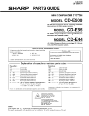
.... MODEL NUMBER 2. PART NO. 4. PARTS GUIDE CD-E500 CD-E55/E44 MINI COMPONENT SYSTEM MODEL CD-E500 CD-E500 Mini Component System consisting of CD-E44 (main unit) and CP-E44 (speaker system). The 13th character represents error. ("J" ±5%, "F" ±1%, "D" ±...;0.5%.) If there are no indications for the electrolytic capacitors, error is ±20%. Be sure to order. 3. No. For U.S.A. "HOW TO ORDER REPLACEMENT PARTS" To have your nearest SHARP...
.... MODEL NUMBER 2. PART NO. 4. PARTS GUIDE CD-E500 CD-E55/E44 MINI COMPONENT SYSTEM MODEL CD-E500 CD-E500 Mini Component System consisting of CD-E44 (main unit) and CP-E44 (speaker system). The 13th character represents error. ("J" ±5%, "F" ±1%, "D" ±...;0.5%.) If there are no indications for the electrolytic capacitors, error is ±20%. Be sure to order. 3. No. For U.S.A. "HOW TO ORDER REPLACEMENT PARTS" To have your nearest SHARP...

