
Instructions for Use
Page 1
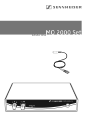
MO 2000 Set Instruction manual 0 20 40 +/- 15dB 0 dB GAIN LEVEL OVERLOAD
MO 2000 Set Instruction manual 0 20 40 +/- 15dB 0 dB GAIN LEVEL OVERLOAD
Instructions for Use
Page 3
Contents Safety instructions...2 MO 2000 Set...4 Delivery includes 5 Product overview MO 2000 Set 6 Putting the system into operation 7 Fitting the device feet 7 Setting up the device 7 Rack mounting ...7 Connecting the mains unit 8 Connecting the amplifier 8 Connecting the optical microphone 9 Switching the central unit on/off 9 Adjusting the sensitivity 9 Overload indication 9 Care and maintenance 10 Accessories...10 Specifications ...11 Connector assignment 12 Frequency response curve 12 Manufacturer Declarations 13 1
Contents Safety instructions...2 MO 2000 Set...4 Delivery includes 5 Product overview MO 2000 Set 6 Putting the system into operation 7 Fitting the device feet 7 Setting up the device 7 Rack mounting ...7 Connecting the mains unit 8 Connecting the amplifier 8 Connecting the optical microphone 9 Switching the central unit on/off 9 Adjusting the sensitivity 9 Overload indication 9 Care and maintenance 10 Accessories...10 Specifications ...11 Connector assignment 12 Frequency response curve 12 Manufacturer Declarations 13 1
Instructions for Use
Page 4
... mains unit to direct sunlight for safe operation or provide additional ventilation. Follow all warnings. Use only the supplied mains unit. not covered or exposed to rain or moisture. Make sure the mechanical loading of time in a closed or multi-rack assembly, please consider that the mains unit is Db] TÜV 07 ATEX 553824 This instruction manual contains important safety information.
... mains unit to direct sunlight for safe operation or provide additional ventilation. Follow all warnings. Use only the supplied mains unit. not covered or exposed to rain or moisture. Make sure the mechanical loading of time in a closed or multi-rack assembly, please consider that the mains unit is Db] TÜV 07 ATEX 553824 This instruction manual contains important safety information.
Instructions for Use
Page 5
... operated only from direct sunlight and similar sources of heat. Ensure sufficient ventilation. Do not expose the device to rain or moisture, does not operate properly or has been dropped. Do not use attachments/accessories specified by a technician. Do not attempt to qualified service personnel. Intended use of this instruction, the warranty becomes null and void. Do not install...
... operated only from direct sunlight and similar sources of heat. Ensure sufficient ventilation. Do not expose the device to rain or moisture, does not operate properly or has been dropped. Do not use attachments/accessories specified by a technician. Do not attempt to qualified service personnel. Intended use of this instruction, the warranty becomes null and void. Do not install...
Instructions for Use
Page 6
... an opto-acoustic microphone head which is connected to be found in areas where aggressive substances (gases, salts, moisture) or radiation are metal-free, including the fiber optic cable feed. The components of the MO 2000 H microphone head (outside dimensions: 1/2 inch) are made of the MO 2000 H microphone head are present. The MO 2000 H is supplied via an external wide voltage range power supply unit. All components of...
... an opto-acoustic microphone head which is connected to be found in areas where aggressive substances (gases, salts, moisture) or radiation are metal-free, including the fiber optic cable feed. The components of the MO 2000 H microphone head (outside dimensions: 1/2 inch) are made of the MO 2000 H microphone head are present. The MO 2000 H is supplied via an external wide voltage range power supply unit. All components of...
Instructions for Use
Page 7
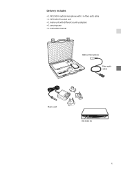
Delivery includes y 1 MO 2000 H optical microphone with 3 m fiber optic cable y 1 MO 2000 CU central unit y 1 mains unit with different country adapters y 1 carrying case y 1 instruction manual Optical microphone Fiber optic cable Mains unit 0 20 40 +/- 15dB 0 dB GAIN LEVEL OVERLOAD MO 2000 CU 5
Delivery includes y 1 MO 2000 H optical microphone with 3 m fiber optic cable y 1 MO 2000 CU central unit y 1 mains unit with different country adapters y 1 carrying case y 1 instruction manual Optical microphone Fiber optic cable Mains unit 0 20 40 +/- 15dB 0 dB GAIN LEVEL OVERLOAD MO 2000 CU 5

Instructions for Use
Page 8
.../OFF button ´ Cable grip for power supply DC cable ² DC socket for connection of power supply unit (DC IN) ¶ Audio output (AF OUT BAL), XLR-3M, balanced º Audio output (AF OUT UNBAL), BNC socket, unbalanced ¾ Type plate µ SC duplex optical connection for microphone Ƹ ƹ ¹ ¸ Optical microphone ¹ SC duplex connector Ƹ Mains unit ƹ US adapter ƺ UK adapter ƻ EU adapter...
.../OFF button ´ Cable grip for power supply DC cable ² DC socket for connection of power supply unit (DC IN) ¶ Audio output (AF OUT BAL), XLR-3M, balanced º Audio output (AF OUT UNBAL), BNC socket, unbalanced ¾ Type plate µ SC duplex optical connection for microphone Ƹ ƹ ¹ ¸ Optical microphone ¹ SC duplex connector Ƹ Mains unit ƹ US adapter ƺ UK adapter ƻ EU adapter...
Instructions for Use
Page 9
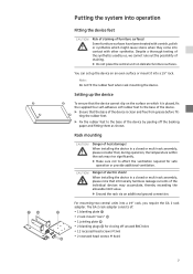
... ground connection. The GA 2 rack adapter consists of the synthetics used by peeling off unused BNC holes y 12 recessed head screws M 3x6 y 2 recessed head screws M 6x10 7 Despite a thorough testing of : y 1 blanking plate Ƽ y 2 rack mount "ears" ƽ y 1 jointing plate ƾ y 2 blanking plugs ƿ for safe operation or ... the surface on an even surface or mount it is clean and free from grease before fit- Setting up the device on which might cause stains when they come into a 19" rack, you require the GA 2 rack adapter. When installing the device in a closed or multi-...
... ground connection. The GA 2 rack adapter consists of the synthetics used by peeling off unused BNC holes y 12 recessed head screws M 3x6 y 2 recessed head screws M 6x10 7 Despite a thorough testing of : y 1 blanking plate Ƽ y 2 rack mount "ears" ƽ y 1 jointing plate ƾ y 2 blanking plugs ƿ for safe operation or ... the surface on an even surface or mount it is clean and free from grease before fit- Setting up the device on which might cause stains when they come into a 19" rack, you require the GA 2 rack adapter. When installing the device in a closed or multi-...

Instructions for Use
Page 10
For details on balanced or unbalanced connection, see "Connector assignment" on automatically. Use the cable grip ᕥ to secure the power supply DC cable. ̈ Connect the suitable adapter to the mains unit Ƹ. ̈ Connect the mains unit Ƹ to the rack. To mount two central units into a rack: ƽ ̈ Place the two central units side by side upside-down onto a flat surface. ̈...
For details on balanced or unbalanced connection, see "Connector assignment" on automatically. Use the cable grip ᕥ to secure the power supply DC cable. ̈ Connect the suitable adapter to the mains unit Ƹ. ̈ Connect the mains unit Ƹ to the rack. To mount two central units into a rack: ƽ ̈ Place the two central units side by side upside-down onto a flat surface. ̈...
Instructions for Use
Page 11
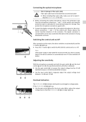
... the connector. Please observe the correct insertion direction of the central unit. Switching the central unit on automatically and the ON button ᕤ lights up . ³·» 9 Adjusting the sensitivity With the microphone connected and both positive and negative voltage peaks. If the OVERLOAD LED » lights up: ̈ Use the gain control ᕡ and/or the level control ᕢ to reduce the output...
... the connector. Please observe the correct insertion direction of the central unit. Switching the central unit on automatically and the ON button ᕤ lights up . ³·» 9 Adjusting the sensitivity With the microphone connected and both positive and negative voltage peaks. If the OVERLOAD LED » lights up: ̈ Use the gain control ᕡ and/or the level control ᕢ to reduce the output...
Instructions for Use
Page 12
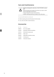
... the mains. ̈ Use a soft, dry cloth to clean the device. To clean the MO 2000 CU central unit: ̈ Before cleaning, disconnect the device from the mains. Care and maintenance CAUTION! Accessories Cat.-No. 009823 525700 525701 067510 502186 511999 516503 Accessory GA 2 rack adapter MO 2000 H optical microphone MO 2000 CU central unit Mains unit MZQ 2000 microphone clamp Carrying case Instruction manual 10 Liquids entering...
... the mains. ̈ Use a soft, dry cloth to clean the device. To clean the MO 2000 CU central unit: ̈ Before cleaning, disconnect the device from the mains. Care and maintenance CAUTION! Accessories Cat.-No. 009823 525700 525701 067510 502186 511999 516503 Accessory GA 2 rack adapter MO 2000 H optical microphone MO 2000 CU central unit Mains unit MZQ 2000 microphone clamp Carrying case Instruction manual 10 Liquids entering...
Instructions for Use
Page 13
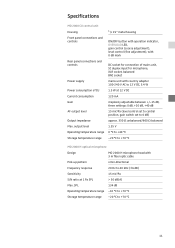
... switch set to 0 dB) approx. 330 Ω unbalanced/660 Ω balanced 1.55 V 0 °C to +40 °C -20 °C to +70 °C MO 2000 H optical microphone Design MO 2000 H microphone head with 3 m fiber optic cable Pick-up pattern Frequency response omni-directional 20 Hz to +70 °C 11 Specifications MO 2000 CU central unit Housing Front panel connections and controls Rear panel connections and controls Power supply Power consumption of mains unit, SC duplex input...
... switch set to 0 dB) approx. 330 Ω unbalanced/660 Ω balanced 1.55 V 0 °C to +40 °C -20 °C to +70 °C MO 2000 H optical microphone Design MO 2000 H microphone head with 3 m fiber optic cable Pick-up pattern Frequency response omni-directional 20 Hz to +70 °C 11 Specifications MO 2000 CU central unit Housing Front panel connections and controls Rear panel connections and controls Power supply Power consumption of mains unit, SC duplex input...

Instructions for Use
Page 14
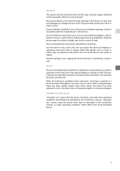
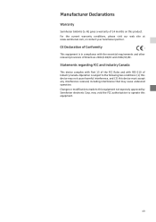
Connection : fiber optic cable - extension (optional) Interface SC Design multimode 200/230 μm Cable loss approx. 3-4 dB per 100 m Optical transducer (optional) Interface socket/socket Design type SC Coupling losses 5-6 dB per coupling pair AF cable Design balanced microphone cable with shielding Connector assignment DC connector for mains unit + 21 3 XLR-3F connector, balanced Frequency response curve dB 20 15 10 5 0 -5 -10 -15 -20 -25 -30 20 50 100 200 500 1k 2k 5k 10k 20k 50k Hz 12
Connection : fiber optic cable - extension (optional) Interface SC Design multimode 200/230 μm Cable loss approx. 3-4 dB per 100 m Optical transducer (optional) Interface socket/socket Design type SC Coupling losses 5-6 dB per coupling pair AF cable Design balanced microphone cable with shielding Connector assignment DC connector for mains unit + 21 3 XLR-3F connector, balanced Frequency response curve dB 20 15 10 5 0 -5 -10 -15 -20 -25 -30 20 50 100 200 500 1k 2k 5k 10k 20k 50k Hz 12
Instructions for Use
Page 15
...and (2) this device must accept any interference received, including interference that may void the FCC authorization to this product. may cause undesired operation. CE Declaration of 24 months on this equipment not expressly approved by Sennheiser electronic Corp. For the current warranty conditions, ...at www.sennheiser.com, or contact your Sennheiser partner. Operation is in compliance with RSS-210 of Directives 2004/108/EC and 2006/95/EC. Changes or modifications made to operate this equipment. 13 Statements regarding FCC and industry Canada This device complies with Part 15 of ...
...and (2) this device must accept any interference received, including interference that may void the FCC authorization to this product. may cause undesired operation. CE Declaration of 24 months on this equipment not expressly approved by Sennheiser electronic Corp. For the current warranty conditions, ...at www.sennheiser.com, or contact your Sennheiser partner. Operation is in compliance with RSS-210 of Directives 2004/108/EC and 2006/95/EC. Changes or modifications made to operate this equipment. 13 Statements regarding FCC and industry Canada This device complies with Part 15 of ...

Instructions for Use
Page 18
KG Am Labor 1 30900 Wedemark, Germany Phone +49 (5130) 600 0 Fax +49 (5130) 600 300 www.sennheiser.com Printed in Germany Publ. 08/08 524194/A01 Sennheiser electronic GmbH & Co.
KG Am Labor 1 30900 Wedemark, Germany Phone +49 (5130) 600 0 Fax +49 (5130) 600 300 www.sennheiser.com Printed in Germany Publ. 08/08 524194/A01 Sennheiser electronic GmbH & Co.

