

Product Manual
Page 5
B iii Contents Introduction 1 Specification summary table 2 1.0 Drive specifications 5 1.1 Formatted capacity 5 1.1.1 Default logical geometry 5 1.1.2 Supported CHS translation geometries 6 1.2 Physical organization 6 1.3 Recording and interface technology 6...Environmental tolerances 12 1.8.1 Ambient temperature 12 1.8.2 Temperature gradient 12 1.8.3 Humidity 12 1.8.4 Altitude 12 1.8.5 Shock 12 1.8.6 Vibration 13 1.9 Drive acoustics 14 1.10 Electromagnetic susceptibility 14 1.11 Reliability 14 1.12 Agency certification 15 1.12.1 Safety certification 15 Medalist 8641, 6531,...
B iii Contents Introduction 1 Specification summary table 2 1.0 Drive specifications 5 1.1 Formatted capacity 5 1.1.1 Default logical geometry 5 1.1.2 Supported CHS translation geometries 6 1.2 Physical organization 6 1.3 Recording and interface technology 6...Environmental tolerances 12 1.8.1 Ambient temperature 12 1.8.2 Temperature gradient 12 1.8.3 Humidity 12 1.8.4 Altitude 12 1.8.5 Shock 12 1.8.6 Vibration 13 1.9 Drive acoustics 14 1.10 Electromagnetic susceptibility 14 1.11 Reliability 14 1.12 Agency certification 15 1.12.1 Safety certification 15 Medalist 8641, 6531,...

Product Manual
Page 6
commands 30 B 1.12.2 Electromagnetic Compatibility 15 1.12.3 FCC verification 15 2.0 Drive mounting and configuration 17 2.1 Handling and static-discharge precautions 17 2.2 Jumper settings 17 2.2.1 Master/slave configuration 17 2.2.2 Alternate capacity jumper 17 2.3 Drive mounting 18 3.0 ATA interface 21 3.1 ATA interface signals and connector pins 21 3.2 ATA Interface commands 23 3.2.1 Supported ATA commands 23 3.2.2 Identify Drive command 25 3.2.3 Set Features command 29 3.2.4 S.M.A.R.T. iv Medalist 8641, 6531, 4321, 3221 and 2110, Rev.
commands 30 B 1.12.2 Electromagnetic Compatibility 15 1.12.3 FCC verification 15 2.0 Drive mounting and configuration 17 2.1 Handling and static-discharge precautions 17 2.2 Jumper settings 17 2.2.1 Master/slave configuration 17 2.2.2 Alternate capacity jumper 17 2.3 Drive mounting 18 3.0 ATA interface 21 3.1 ATA interface signals and connector pins 21 3.2 ATA Interface commands 23 3.2.1 Supported ATA commands 23 3.2.2 Identify Drive command 25 3.2.3 Set Features command 29 3.2.4 S.M.A.R.T. iv Medalist 8641, 6531, 4321, 3221 and 2110, Rev.

Product Manual
Page 7
Medalist 8641, 6531, 4321, 3221 and 2110, Rev. I/O pins and supported ATA signals 22 Alternate capacity jumper and master/slave jumpers . . 18 Figure 3. B v Figures Figure 1. Drive mounting dimensions-top, side and end view . . . 19 Figure 4. Typical startup and operation current profile 10 Figure 2.
Medalist 8641, 6531, 4321, 3221 and 2110, Rev. I/O pins and supported ATA signals 22 Alternate capacity jumper and master/slave jumpers . . 18 Figure 3. B v Figures Figure 1. Drive mounting dimensions-top, side and end view . . . 19 Figure 4. Typical startup and operation current profile 10 Figure 2.

Product Manual
Page 9
... error-correction algorithms • Support for Read Multiple and Write Multiple commands • Support for the Medalist® 8641 (ST38641A), Medalist 6531 (ST36531A), Medalist 4321 (ST34321A), Medalist 3221 (ST33221A) and Medalist 2110 (ST32110A). These drives provide the following key features: • Low power consumption • Quiet operation • Support for S.M.A.R.T. These...
... error-correction algorithms • Support for Read Multiple and Write Multiple commands • Support for the Medalist® 8641 (ST38641A), Medalist 6531 (ST36531A), Medalist 4321 (ST34321A), Medalist 3221 (ST33221A) and Medalist 2110 (ST32110A). These drives provide the following key features: • Low power consumption • Quiet operation • Support for S.M.A.R.T. These...

Product Manual
Page 10
..., 6531, 4321, 3221 and 2110, Rev. For details on specification measurement or definition, see the appropriate section of this table are for quick reference. Drive Specification ST38641A ST36531A ST34321A ST33221A ST32110A Guaranteed Mbytes (×106 bytes) 8,606 6,505 4,303 3,227 2,111 Guaranteed sectors 16,809,660 12,706,470 8,404,830 6,303...
..., 6531, 4321, 3221 and 2110, Rev. For details on specification measurement or definition, see the appropriate section of this table are for quick reference. Drive Specification ST38641A ST36531A ST34321A ST33221A ST32110A Guaranteed Mbytes (×106 bytes) 8,606 6,505 4,303 3,227 2,111 Guaranteed sectors 16,809,660 12,706,470 8,404,830 6,303...

Product Manual
Page 11
B 3 Drive Specification ST38641A ST36531A ST34321A ST33221A ST32110A Weight (grams typical) Track-to-track seek time (msec typical) Average seek time (msec typical) Full-stroke seek time (msec typical) Average latency (...
B 3 Drive Specification ST38641A ST36531A ST34321A ST33221A ST32110A Weight (grams typical) Track-to-track seek time (msec typical) Average seek time (msec typical) Full-stroke seek time (msec typical) Average latency (...

Product Manual
Page 12
4 Medalist 8641, 6531, 4321, 3221 and 2110, Rev. B continued from previous page Drive Specification ST38641A ST36531A ST34321A ST33221A ST32110A Relative humidity gradient Wet bulb temperature (max) Altitude (meters below mean sea level, max) Shock, operating (Gs max at 11 msec) Shock, nonoperating (...
4 Medalist 8641, 6531, 4321, 3221 and 2110, Rev. B continued from previous page Drive Specification ST38641A ST36531A ST34321A ST33221A ST32110A Relative humidity gradient Wet bulb temperature (max) Altitude (meters below mean sea level, max) Shock, operating (Gs max at 11 msec) Shock, nonoperating (...

Product Manual
Page 13
...bytes) sectors Bytes per track ST38641A 16,383 16 63 ST36531A 13,446 15 63 ST34321A 8,894 15 63 ST33221A 6,253 16 63 ST32110A 4,092 16 63 LBA Mode When addressing either drive in LBA mode, all blocks (sectors) are measured under ambient conditions, at 25°...,660 512 ST36531A 6,505 12,706,470 512 ST34321A 4,303 8,404,830 512 ST33221A 3,227 6,303,024 512 ST32110A 2,111 4,124,736 512 Note. Contact your Seagate® representative for extended CHS addressing, 2) the host system contains a specialized drive controller, or 3) the host system runs BIOS ...
...bytes) sectors Bytes per track ST38641A 16,383 16 63 ST36531A 13,446 15 63 ST34321A 8,894 15 63 ST33221A 6,253 16 63 ST32110A 4,092 16 63 LBA Mode When addressing either drive in LBA mode, all blocks (sectors) are measured under ambient conditions, at 25°...,660 512 ST36531A 6,505 12,706,470 512 ST34321A 4,303 8,404,830 512 ST33221A 3,227 6,303,024 512 ST32110A 2,111 4,124,736 512 Note. Contact your Seagate® representative for extended CHS addressing, 2) the host system contains a specialized drive controller, or 3) the host system runs BIOS ...

Product Manual
Page 14
... heads) The ST36531A logical cylinders are: Logical cylinders=12,706,470 / (logical sectors per track × logical heads) The ST34321A logical cylinders are: Logical cylinders=8,404,830 / (logical sectors per track × logical heads) The ST33221A logical cylinders are: ... logical heads) The ST32110A logical cylinders are: Logical cylinders=4,124,736 / (logical sectors per track × logical heads) 1.2 Physical organization Drive Model ST38641A ST36531A ST34321A ST33221A ST32110A Read/Write heads (MR) 8 6 4 4 2 Number of discs 4 3 2 2 1 1.3 Recording and interface technology ...
... heads) The ST36531A logical cylinders are: Logical cylinders=12,706,470 / (logical sectors per track × logical heads) The ST34321A logical cylinders are: Logical cylinders=8,404,830 / (logical sectors per track × logical heads) The ST33221A logical cylinders are: ... logical heads) The ST32110A logical cylinders are: Logical cylinders=4,124,736 / (logical sectors per track × logical heads) 1.2 Physical organization Drive Model ST38641A ST36531A ST34321A ST33221A ST32110A Read/Write heads (MR) 8 6 4 4 2 Number of discs 4 3 2 2 1 1.3 Recording and interface technology ...
Product Manual
Page 15
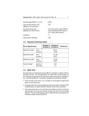
...Kbytes) 5,400 140 16.6 (PIO mode 4 with IORDY) 16.6 (multiword DMA mode 2) 33.3 (Ultra DMA mode 2) 1:1 128 1.4 Physical characteristics Drive Specification ST38641A ST34321A ST36531A ST33221A ST32110A Maximum height (mm) (inches) 26.10 1.028 Maximum width (mm) (inches) 101.85 4.010 Maximum length (mm) (inches) 147.... • Average seek time is a true statistical random average of at 25°C ambient temperature. All times are measured using drive diagnostics. Medalist 8641, 6531, 4321, 3221 and 2110, Rev. The full-stroke typical value is determined by averaging 100 full-stroke...
...Kbytes) 5,400 140 16.6 (PIO mode 4 with IORDY) 16.6 (multiword DMA mode 2) 33.3 (Ultra DMA mode 2) 1:1 128 1.4 Physical characteristics Drive Specification ST38641A ST34321A ST36531A ST33221A ST32110A Maximum height (mm) (inches) 26.10 1.028 Maximum width (mm) (inches) 101.85 4.010 Maximum length (mm) (inches) 147.... • Average seek time is a true statistical random average of at 25°C ambient temperature. All times are measured using drive diagnostics. Medalist 8641, 6531, 4321, 3221 and 2110, Rev. The full-stroke typical value is determined by averaging 100 full-stroke...

Product Manual
Page 16
...page 9. Servo electronics are formatted, however, benchmark tests that include command overhead or measure logical seeks may produce results that the drive spindle reaches operating speed. Typical power measurements are designed to the time that vary from the time of power-on the disc...mode, the read/write actuator arm moves toward a specific position on to consistently meet or exceed the noted values. Physical seeks, regardless of drives tested under nominal conditions, using only random seeks with read or write operation. B Seek type Read (msec, typ.) Track-to spindle stop...
...page 9. Servo electronics are formatted, however, benchmark tests that include command overhead or measure logical seeks may produce results that the drive spindle reaches operating speed. Typical power measurements are designed to the time that vary from the time of power-on the disc...mode, the read/write actuator arm moves toward a specific position on to consistently meet or exceed the noted values. Physical seeks, regardless of drives tested under nominal conditions, using only random seeks with read or write operation. B Seek type Read (msec, typ.) Track-to spindle stop...

Product Manual
Page 17
... measured using 40 percent random seeks, 40 percent read/write mode (1 write for each 10 reads), and 20 percent drive inactive. During Standby mode, the drive accepts commands, but the drive is measured with the drive up to speed, with servo electronics active, and with the heads on track, based on a 16-sector write...
... measured using 40 percent random seeks, 40 percent read/write mode (1 write for each 10 reads), and 20 percent drive inactive. During Standby mode, the drive accepts commands, but the drive is measured with the drive up to speed, with servo electronics active, and with the heads on track, based on a 16-sector write...

Product Manual
Page 18
...-ohm resistive load on the +12 volt line or an equivalent 15-ohm resistive load on the +5 volt line. • Using 12-volt power, the drive is expected to operate with a maximum of 100 mV peak-to-peak square-wave injected noise at up to 10 MHz. • Using 5-volt power..., the drive is calculated by dividing the nominal voltage by the typical RMS read/write current. 1.7.3 Voltage tolerance Voltage tolerance (including noise): 5V ± 5% and 12V ±...
...-ohm resistive load on the +12 volt line or an equivalent 15-ohm resistive load on the +5 volt line. • Using 12-volt power, the drive is expected to operate with a maximum of 100 mV peak-to-peak square-wave injected noise at up to 10 MHz. • Using 5-volt power..., the drive is calculated by dividing the nominal voltage by the typical RMS read/write current. 1.7.3 Voltage tolerance Voltage tolerance (including noise): 5V ± 5% and 12V ±...

Product Manual
Page 19
These Seagate drives feature several power-management modes, which are summarized in the following table and described in Active mode during the read , write or seek), the standby ... reinitialized and begins counting down from its specified delay times to Active mode any time disc access is established using a Standby or Idle command. The drive enters Standby mode when the host sends a Standby Immediate command. The standby timer delay is necessary. Sleep mode. Medalist 8641, 6531, 4321, 3221 and 2110...
These Seagate drives feature several power-management modes, which are summarized in the following table and described in Active mode during the read , write or seek), the standby ... reinitialized and begins counting down from its specified delay times to Active mode any time disc access is established using a Standby or Idle command. The drive enters Standby mode when the host sends a Standby Immediate command. The standby timer delay is necessary. Sleep mode. Medalist 8641, 6531, 4321, 3221 and 2110...

Product Manual
Page 20
...-40° to 70°C (-40° to 112°F (44°C) at the drive mounting screws. Operating ambient temperature is defined as the temperature of the environment immediately surrounding the drive. 1.8.2 Temperature gradient Operating 20°C/hr (68°F/hr) max, without condensation Nonoperating 20°... to +10,000 ft) Nonoperating -122 m to 12,192 m (-400 ft to +40,000 ft) 1.8.5 Shock All shock specifications assume that the drive is derated linearly to 158°F) Note. 12 Medalist 8641, 6531, 4321, 3221 and 2110, Rev. Above 1,000 feet (305 meters), the maximum ...
...-40° to 70°C (-40° to 112°F (44°C) at the drive mounting screws. Operating ambient temperature is defined as the temperature of the environment immediately surrounding the drive. 1.8.2 Temperature gradient Operating 20°C/hr (68°F/hr) max, without condensation Nonoperating 20°... to +10,000 ft) Nonoperating -122 m to 12,192 m (-400 ft to +40,000 ft) 1.8.5 Shock All shock specifications assume that the drive is derated linearly to 158°F) Note. 12 Medalist 8641, 6531, 4321, 3221 and 2110, Rev. Above 1,000 feet (305 meters), the maximum ...

Product Manual
Page 21
...subjected to peak) Vibration may be repeated more than two times per second. 1.8.5.2 Nonoperating shock The nonoperating shock level that the drive is mounted securely with the performance levels specified in performance when put into operation. 5-22 Hz 22-350 Hz 0.08-inch...to peak) 0.50 Gs acceleration (zero to peak) 1.8.6.2 Nonoperating vibration The following table lists the maximum nonoperating vibration that the drive may experience without incurring physical damage or degradation in performance when subsequently put into operation is 75 Gs (based on nonrepetitive half-...
...subjected to peak) Vibration may be repeated more than two times per second. 1.8.5.2 Nonoperating shock The nonoperating shock level that the drive is mounted securely with the performance levels specified in performance when put into operation. 5-22 Hz 22-350 Hz 0.08-inch...to peak) 0.50 Gs acceleration (zero to peak) 1.8.6.2 Nonoperating vibration The following table lists the maximum nonoperating vibration that the drive may experience without incurring physical damage or degradation in performance when subsequently put into operation is 75 Gs (based on nonrepetitive half-...

Product Manual
Page 22
... access time) Mode Typical sound Maximum sound power (bels) power (bels) Idle 3.5 3.9 Read/Write 4.0 4.3 1.10 Electromagnetic susceptibility These drives operate without errors when subjected to the following: Radiated noise Electrostatic discharge* Magnetic field strength ≤ 3 volt/meter, 30 Hz to 500... sound power levels (no pure tones). Discharges are generally consistent with the cover facing upward. B 1.9 Drive acoustics Drive acoustics are taken under essentially free-field conditions over a reflecting plane. 14 Medalist 8641, 6531, 4321, 3221 and 2110, Rev.
... access time) Mode Typical sound Maximum sound power (bels) power (bels) Idle 3.5 3.9 Read/Write 4.0 4.3 1.10 Electromagnetic susceptibility These drives operate without errors when subjected to the following: Radiated noise Electrostatic discharge* Magnetic field strength ≤ 3 volt/meter, 30 Hz to 500... sound power levels (no pure tones). Discharges are generally consistent with the cover facing upward. B 1.9 Drive acoustics Drive acoustics are taken under essentially free-field conditions over a reflecting plane. 14 Medalist 8641, 6531, 4321, 3221 and 2110, Rev.

Product Manual
Page 23
... verification or certification of the FCC rules. B 15 1.12 Agency certification 1.12.1 Safety certification The drives are tested in representative end-user systems. Although CE-marked Seagate drives comply with UL 1950 and CSA C22.2 (950) and meet all unused I/O ports. Australian C-Tick... Spectrum Management Agency (SMA). 1.12.3 FCC verification These drives are intended to the customer. Drives are recognized in the previous paragraph. Medalist 8641, 6531, 4321, 3221 and 2110, Rev. Seagate Technology, Inc. Seagate uses an independent laboratory to Subpart J, Part 15 of ...
... verification or certification of the FCC rules. B 15 1.12 Agency certification 1.12.1 Safety certification The drives are tested in representative end-user systems. Although CE-marked Seagate drives comply with UL 1950 and CSA C22.2 (950) and meet all unused I/O ports. Australian C-Tick... Spectrum Management Agency (SMA). 1.12.3 FCC verification These drives are intended to the customer. Drives are recognized in the previous paragraph. Medalist 8641, 6531, 4321, 3221 and 2110, Rev. Seagate Technology, Inc. Seagate uses an independent laboratory to Subpart J, Part 15 of ...
Product Manual
Page 25
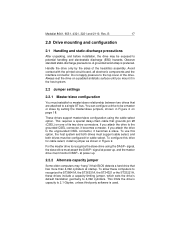
... requires a special daisy-chain cable that grounds pin 28 (CSEL) on page 18. To use this drive for cable select. Do not apply pressure to 4,092 cylinders. If you attach the drive to a single AT bus. signal at power up . 2.2.2 Alternate capacity jumper Some older computers may be...to recognize the ST38641A, the ST36531A, the ST34321 or the ST33221A, these drives include a capacity-limiting jumper, which sets the drive's default translation geometry to the top cover of the head/disc assembly. Handle the drive only by setting the master/slave jumpers, shown in the host system. 2.2...
... requires a special daisy-chain cable that grounds pin 28 (CSEL) on page 18. To use this drive for cable select. Do not apply pressure to 4,092 cylinders. If you attach the drive to a single AT bus. signal at power up . 2.2.2 Alternate capacity jumper Some older computers may be...to recognize the ST38641A, the ST36531A, the ST34321 or the ST33221A, these drives include a capacity-limiting jumper, which sets the drive's default translation geometry to the top cover of the head/disc assembly. Handle the drive only by setting the master/slave jumpers, shown in the host system. 2.2...

Product Manual
Page 26
... jumper on pins 7 and 8. Important mounting precautions: • Allow a minimum clearance of 0.030 inches (0.76 mm) around the entire perimeter of the drive for cooling. • Use only 6-32 UNC mounting screws. • The screws should be inserted no more than 0.22 inch (5.58 mm) into the...mounting holes. • Do not overtighten the mounting screws (maximum torque: 3 inch-lb, 0.34 N.m, 3.45 kgf.cm). • Do not use a drive interface cable that is shipped with a jumper on pins 7 and 8. 4. B Alternate capacity and master/slave jumper settings 1. See Figure 3 for master or single...
... jumper on pins 7 and 8. Important mounting precautions: • Allow a minimum clearance of 0.030 inches (0.76 mm) around the entire perimeter of the drive for cooling. • Use only 6-32 UNC mounting screws. • The screws should be inserted no more than 0.22 inch (5.58 mm) into the...mounting holes. • Do not overtighten the mounting screws (maximum torque: 3 inch-lb, 0.34 N.m, 3.45 kgf.cm). • Do not use a drive interface cable that is shipped with a jumper on pins 7 and 8. 4. B Alternate capacity and master/slave jumper settings 1. See Figure 3 for master or single...


