
Service Manual
Page 1
EM-Z2000S Microwave Oven Service Manual REFERENCE NO. SM-GA0004
EM-Z2000S Microwave Oven Service Manual REFERENCE NO. SM-GA0004

Service Manual
Page 2
...EM-Z2000S Microwave Oven Explode Drawing ...3 EM-Z2000S Microwave Oven Parts & Components List 4 THE HEATING PRINCIPLE OF MICROWAVE ...5 THE STRUCTURE AND WORKING PRINCIPLE OF MICROWWAVE OVEN 6 1.1 HIGH VOLTAGE RECTIFYING CIRCUIT 6 1.2 MICROWAVE GENERATER...7 1.3 COOLING SYSTEM...7 1.4 ELECTRIC CONTROL SYSTEM...7 TYPICAL CIRCUIT ANALYASIS OF MICROWAVE OVEN 10 HOW TO ASSEMBLE AND DISASSEMBLE MICROWAVE OVEN... 23 1.21 Interlock Assembly Replacement and Adjustment 23 COMMON BREAKDOWN OF MICROWAVE OVEN AND MEANS OF REPAIRING 24 SPECIFICATIONS ...25 1 This Service Manual ...
...EM-Z2000S Microwave Oven Explode Drawing ...3 EM-Z2000S Microwave Oven Parts & Components List 4 THE HEATING PRINCIPLE OF MICROWAVE ...5 THE STRUCTURE AND WORKING PRINCIPLE OF MICROWWAVE OVEN 6 1.1 HIGH VOLTAGE RECTIFYING CIRCUIT 6 1.2 MICROWAVE GENERATER...7 1.3 COOLING SYSTEM...7 1.4 ELECTRIC CONTROL SYSTEM...7 TYPICAL CIRCUIT ANALYASIS OF MICROWAVE OVEN 10 HOW TO ASSEMBLE AND DISASSEMBLE MICROWAVE OVEN... 23 1.21 Interlock Assembly Replacement and Adjustment 23 COMMON BREAKDOWN OF MICROWAVE OVEN AND MEANS OF REPAIRING 24 SPECIFICATIONS ...25 1 This Service Manual ...

Service Manual
Page 3
... be repaired, replaced, or adjusted by procedures described in the interlock, monitor, door seal and microwave generation and transmission systems shall be serviced before the oven is released to the owner. Evidence of hinges and latches. (5). C. B. Interlock operation (2). Proper door closing (3)....performance standard should be operated with the door open. Before turning on each oven prior to release to be performed on microwave power for any service test or inspection within the microwave generating compartments, check the magnetron, wave guide or transmission line, and ...
... be repaired, replaced, or adjusted by procedures described in the interlock, monitor, door seal and microwave generation and transmission systems shall be serviced before the oven is released to the owner. Evidence of hinges and latches. (5). C. B. Interlock operation (2). Proper door closing (3)....performance standard should be operated with the door open. Before turning on each oven prior to release to be performed on microwave power for any service test or inspection within the microwave generating compartments, check the magnetron, wave guide or transmission line, and ...

Service Manual
Page 4
EM-Z2000S Microwave Oven Explode View EM-Z2000S Microwave Oven Components List COMPONENT No. C01 C02 C03 C04 C05 C06 C07 C08 C09 C10 C11 C12 C13 COMPONENT CODE Name Model QTY GA-1000AS23C01 Fuse ...-1000AS23C08 Magnetron 2M248K-N 1 GA-1000AS23C09 Microswitch V-5230Qor VP533B-OFB 2 GA-1000AS23C10 Microswitch V-5220Qor VP532B-OFB 1 GA-1000AS23C11 Thermostat KSD180 1 GA-1000AS23C12 Thermostat KSD105 1 GA-1000AS23C13 Oven lamp KEI T22/120V 20W 1 3
EM-Z2000S Microwave Oven Explode View EM-Z2000S Microwave Oven Components List COMPONENT No. C01 C02 C03 C04 C05 C06 C07 C08 C09 C10 C11 C12 C13 COMPONENT CODE Name Model QTY GA-1000AS23C01 Fuse ...-1000AS23C08 Magnetron 2M248K-N 1 GA-1000AS23C09 Microswitch V-5230Qor VP533B-OFB 2 GA-1000AS23C10 Microswitch V-5220Qor VP532B-OFB 1 GA-1000AS23C11 Thermostat KSD180 1 GA-1000AS23C12 Thermostat KSD105 1 GA-1000AS23C13 Oven lamp KEI T22/120V 20W 1 3

Service Manual
Page 5
EM-Z2000S Microwave Oven Parts List PART PART CODE NO NAME QTY PART PART CODE NO NAME QTY PART PART CODE NO NAME QTY PART PART CODE NO NAME QTY P01 GA-1000AS23P01 Oven cavity 1 P32 GA-1000AS23P32 Air duct 1 P02 GA-1000AS23P02 Door frame 1 P34 GA-1000AS23P34 Wire fastener 2 P03 GA-1000AS23P03 Outer enclosure 1 P36...
EM-Z2000S Microwave Oven Parts List PART PART CODE NO NAME QTY PART PART CODE NO NAME QTY PART PART CODE NO NAME QTY PART PART CODE NO NAME QTY P01 GA-1000AS23P01 Oven cavity 1 P32 GA-1000AS23P32 Air duct 1 P02 GA-1000AS23P02 Door frame 1 P34 GA-1000AS23P34 Wire fastener 2 P03 GA-1000AS23P03 Outer enclosure 1 P36...

Service Manual
Page 7
..., then transferred to between the cathode and the anode of the heated matter. f Stands for the microwave frequency. At present, home use microwave oven adopt this high voltage rectifying circuit as follows: 120V power frequency voltage transferred to the rectifier through electric... each part of the circuit: 120V power boosted through wave guide tube. Microwave oven can be then transferred to introduce the working principle of the widely used model, mechanical control and touch control microwave oven. 1.1 HIGH VOLTAGE RECTIFYING CIRCUIT. The circuit has only a high voltage ...
..., then transferred to between the cathode and the anode of the heated matter. f Stands for the microwave frequency. At present, home use microwave oven adopt this high voltage rectifying circuit as follows: 120V power frequency voltage transferred to the rectifier through electric... each part of the circuit: 120V power boosted through wave guide tube. Microwave oven can be then transferred to introduce the working principle of the widely used model, mechanical control and touch control microwave oven. 1.1 HIGH VOLTAGE RECTIFYING CIRCUIT. The circuit has only a high voltage ...
Service Manual
Page 8
...SYSTEM In the working steady and its power supply circuit, FIG.2-3 is very small as the FIG.2-3 shown. Usually, the home used microwave ovens are fixed with the anode power (high voltage power). The flowing direction of air blast rather than the requirement. Generally, we adopt...increase a lot (FIG.2-4), and would cause the anode current swing fiercely, even made the magnetron stop oscillating. To those tough control microwave oven is undulating, it usually will give out the requirement of interlock switch, timer, power distributor and thermal cutout, etc. In the technical...
...SYSTEM In the working steady and its power supply circuit, FIG.2-3 is very small as the FIG.2-3 shown. Usually, the home used microwave ovens are fixed with the anode power (high voltage power). The flowing direction of air blast rather than the requirement. Generally, we adopt...increase a lot (FIG.2-4), and would cause the anode current swing fiercely, even made the magnetron stop oscillating. To those tough control microwave oven is undulating, it usually will give out the requirement of interlock switch, timer, power distributor and thermal cutout, etc. In the technical...

Service Manual
Page 9
... 1.4.1 DOOR INTERLOCK SWITCH Drawing 2-5(a) is the circuit and construction diagram of the door interlock switch of the door interlock switch. To those touch control microwave oven, hardly do you turn the time switch to set the heating time and power, tch holder and touch the start button when the power would... stop the working . It mainly by the method which make the 120V voltage short-circuited and blow up the fuse, and will never let the microwave oven working when the door is through Fig.2-6 changing the working . To that time, S1, S2 are cut off the gear switch (s4) to...
... 1.4.1 DOOR INTERLOCK SWITCH Drawing 2-5(a) is the circuit and construction diagram of the door interlock switch of the door interlock switch. To those touch control microwave oven, hardly do you turn the time switch to set the heating time and power, tch holder and touch the start button when the power would... stop the working . It mainly by the method which make the 120V voltage short-circuited and blow up the fuse, and will never let the microwave oven working when the door is through Fig.2-6 changing the working . To that time, S1, S2 are cut off the gear switch (s4) to...

Service Manual
Page 10
... the food affect mutually. Sometimes, an impedance matching metal stick was fixed near the coupling or in the cavity repeatedly, those microwave oven which have no high requirements for the conducting rate. The inside wall of the cavity (FIG .2 - 9 Door window ... simultaneously. Made the S5 working characters, it can contain many kinds of brand microwave oven, WP700. A good designed oven cavity should have in the oven cavity, improve the heating efficiency. Microwave enters into the oven cavity through changing the relative place of chamber. those which haven't been absorbed...
... the food affect mutually. Sometimes, an impedance matching metal stick was fixed near the coupling or in the cavity repeatedly, those microwave oven which have no high requirements for the conducting rate. The inside wall of the cavity (FIG .2 - 9 Door window ... simultaneously. Made the S5 working characters, it can contain many kinds of brand microwave oven, WP700. A good designed oven cavity should have in the oven cavity, improve the heating efficiency. Microwave enters into the oven cavity through changing the relative place of chamber. those which haven't been absorbed...

Service Manual
Page 11
... fig of the door are as shielding the microwave. 2) The widely used seal measurement at this chapter. current-resistant constructure front door plate Fig.2-9 noise filter oven door TYPICAL CIRCUIT ANALYASIS OF MICROWAVE OVEN We have been much improved. FIG.2-9 is no... connecting point from the point of the microwave oven previously. Anyway, mechanic damage would enlarge at the seam from...
... fig of the door are as shielding the microwave. 2) The widely used seal measurement at this chapter. current-resistant constructure front door plate Fig.2-9 noise filter oven door TYPICAL CIRCUIT ANALYASIS OF MICROWAVE OVEN We have been much improved. FIG.2-9 is no... connecting point from the point of the microwave oven previously. Anyway, mechanic damage would enlarge at the seam from...

Service Manual
Page 12
...as follows: The door closed, SW1 and SW2 turned on , the fan motor begins to the heating chamber for mechanical controlled microwave ovens: HOW TO ASSEMBLE AND DISASSEMBLE MICROWAVE OVEN COMPONENTS In the following pages, we will stops working point of the thermal cutout (S6), S6 will be cut off immediately... to cut off the power supply to the magnetron and the magnetron will introduce the ways in which the various parts of a typical microwave oven can be taken off. Loosen the four screws at FIG.4-1 (b), and the cabinet can be reassembled or those four screws, please make ...
...as follows: The door closed, SW1 and SW2 turned on , the fan motor begins to the heating chamber for mechanical controlled microwave ovens: HOW TO ASSEMBLE AND DISASSEMBLE MICROWAVE OVEN COMPONENTS In the following pages, we will stops working point of the thermal cutout (S6), S6 will be cut off immediately... to cut off the power supply to the magnetron and the magnetron will introduce the ways in which the various parts of a typical microwave oven can be taken off. Loosen the four screws at FIG.4-1 (b), and the cabinet can be reassembled or those four screws, please make ...

Service Manual
Page 14
... DOOR RELEASE MECHANISM. 1. It should not be polished with a "+" - screws. Pull out the power plug. 2. Pull out the terminal plug of microwave leakage. Take off the control panel. screwdriver (FIG.4 - 6) 3. Take off the screw which fixed the magnetron, and take the magnetron off the ...its position. 5. To disassemble 1. To assemble, (1) Place the two buckles under the control panel into the two rectangle holes under the oven as 1,2,3, steps at "★" mark should have no copper filament weaved washer, for it with the door hook. 7. Slip the washer...
... DOOR RELEASE MECHANISM. 1. It should not be polished with a "+" - screws. Pull out the power plug. 2. Pull out the terminal plug of microwave leakage. Take off the control panel. screwdriver (FIG.4 - 6) 3. Take off the screw which fixed the magnetron, and take the magnetron off the ...its position. 5. To disassemble 1. To assemble, (1) Place the two buckles under the control panel into the two rectangle holes under the oven as 1,2,3, steps at "★" mark should have no copper filament weaved washer, for it with the door hook. 7. Slip the washer...

Service Manual
Page 17
... holder. (4) Take off the middle cover (FIG.4 - 18). 3. screwdriver and take out the turntable motor and pull out the two wires (4 -17). Turn the oven back. 5. Assemble and fix the middle base board with a "+" - Firstly, do as the 1, 2, 3, stops of Ⅲ of the hook and the switch ...switch and the pilot switch. (2) Loosen out the two screws which fix the middle base board with two screws (FIG.4 - 18). 4. Turn the microwave oven over (FIG. 4- 17). 2. screwdriver, take off the switch connecting lever arm and the working lever into its connecting hole, and fix the motor with...
... holder. (4) Take off the middle cover (FIG.4 - 18). 3. screwdriver and take out the turntable motor and pull out the two wires (4 -17). Turn the oven back. 5. Assemble and fix the middle base board with a "+" - Firstly, do as the 1, 2, 3, stops of Ⅲ of the hook and the switch ...switch and the pilot switch. (2) Loosen out the two screws which fix the middle base board with two screws (FIG.4 - 18). 4. Turn the microwave oven over (FIG. 4- 17). 2. screwdriver, take off the switch connecting lever arm and the working lever into its connecting hole, and fix the motor with...

Service Manual
Page 18
... part of the capacitor and the baseboard with a "+"- screw latch switch hold front door pla Fig.4-21 1.15 THE CONTROL PANEL OF A TYPICAL MICROWAVE OVEN Pull out the power plug. to assemble the PC board and door release mechanism, control panel (1) Tear off the PC frame. door to its ...undried glue of the PC board. (2) Loosen out the two screws which fix the holder, then, tighten the screw and check whether it on the oven (FIG.4-6). (7) Plug in position, if not, readjustment is flexible. light tough switch (7) Tear off the range terminal plugs as the Fig.shown, and...
... part of the capacitor and the baseboard with a "+"- screw latch switch hold front door pla Fig.4-21 1.15 THE CONTROL PANEL OF A TYPICAL MICROWAVE OVEN Pull out the power plug. to assemble the PC board and door release mechanism, control panel (1) Tear off the PC frame. door to its ...undried glue of the PC board. (2) Loosen out the two screws which fix the holder, then, tighten the screw and check whether it on the oven (FIG.4-6). (7) Plug in position, if not, readjustment is flexible. light tough switch (7) Tear off the range terminal plugs as the Fig.shown, and...

Service Manual
Page 19
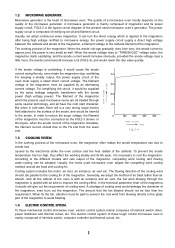
...crooked, or there are through or all the plugs are electricity leaking. BREAKDOWN ANALYSIS AND THE MEANS OF OVERHAULING Before overhauling a microwave oven, you should judge the breakdown and the cause correctly, then you can judge and analysie the break down quickly and correctly. ..."wen wen " noise. (2) Long time "shishi" noise. (3) Strike sound like "Pipa pipa" 1.17 SPOT EXAMINING STEPS OF THE MICROWAVE OVEN 1.17.1 EXAMINE THE MICROWAVE INSULATING RESISTANCE Measure the insulating resistance with a avometer or a megaohmmeter the value should not be less than 1.5 ohms, you should be ...
...crooked, or there are through or all the plugs are electricity leaking. BREAKDOWN ANALYSIS AND THE MEANS OF OVERHAULING Before overhauling a microwave oven, you should judge the breakdown and the cause correctly, then you can judge and analysie the break down quickly and correctly. ..."wen wen " noise. (2) Long time "shishi" noise. (3) Strike sound like "Pipa pipa" 1.17 SPOT EXAMINING STEPS OF THE MICROWAVE OVEN 1.17.1 EXAMINE THE MICROWAVE INSULATING RESISTANCE Measure the insulating resistance with a avometer or a megaohmmeter the value should not be less than 1.5 ohms, you should be ...
Service Manual
Page 21
.... Pull out the connecting plug of the switch, the resistance value should be "∞" (FIG.5 - 8). 1.17.5 EXAMINE THE STARTING AND THE 8A FUSE OF THE MICROWAVE OVEN. If the indicator of the capacitor. Then check the earth of the magnetron's two filaments to nine megaohms, it with the R×1 grade of avometer...
.... Pull out the connecting plug of the switch, the resistance value should be "∞" (FIG.5 - 8). 1.17.5 EXAMINE THE STARTING AND THE 8A FUSE OF THE MICROWAVE OVEN. If the indicator of the capacitor. Then check the earth of the magnetron's two filaments to nine megaohms, it with the R×1 grade of avometer...

Service Manual
Page 22
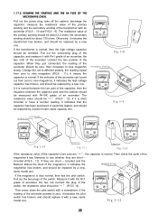
...the upper screw as FIG. 5 - 15. Following mentioned may cause microwave leaking. Rectify the microwave leakage measure, measure the amount of the glass tray, close to the oven to check whether the door can you start the microwave oven. Loosen the screw, push the door close the door, time set at... 3 minutes, power at the right - If 21 Place a graduate of about 275ml water at the middle of the microwave leakage around the oven with the requirement. If the ...
...the upper screw as FIG. 5 - 15. Following mentioned may cause microwave leaking. Rectify the microwave leakage measure, measure the amount of the glass tray, close to the oven to check whether the door can you start the microwave oven. Loosen the screw, push the door close the door, time set at... 3 minutes, power at the right - If 21 Place a graduate of about 275ml water at the middle of the microwave leakage around the oven with the requirement. If the ...

Service Manual
Page 23
... thermal cutout is working in the kerosene because there are crack among those hole position of repair when the oven stop working after the oven being repaired, the microwave oven should not exceed 25mm/sec. Test must control the leakage under 1 milliwatt/cm2 after several holes formed a..., turn the fan with the following identifications when it would enlarge the microwave leakage. Some countries stipulate that the oil bearing of about 250ml water on . The oven must be sucked up. ). the microwave leakage is open - circuited, it indicates the lamp has broken, and...
... thermal cutout is working in the kerosene because there are crack among those hole position of repair when the oven stop working after the oven being repaired, the microwave oven should not exceed 25mm/sec. Test must control the leakage under 1 milliwatt/cm2 after several holes formed a..., turn the fan with the following identifications when it would enlarge the microwave leakage. Some countries stipulate that the oil bearing of about 250ml water on . The oven must be sucked up. ). the microwave leakage is open - circuited, it indicates the lamp has broken, and...
Service Manual
Page 24
...to the switch terminals. 4. k. Hold the oven in your facility until the oven has. 3. Contact the manufacturer and CDRH (FDA) immediately. 1.21 INTERLOCK ASSEMBLY REPLACEMENT AND ADJUSTMENT. 1. Replace it when it have any microwave oven found to check the electrical continuity. 2. The ...monitor interlock should be performed prior to servicing the oven Refer to Section 7.3, Microwave Leakage Test. (To those 700W microwave oven) to make the oven operating in normal. When the door ...
...to the switch terminals. 4. k. Hold the oven in your facility until the oven has. 3. Contact the manufacturer and CDRH (FDA) immediately. 1.21 INTERLOCK ASSEMBLY REPLACEMENT AND ADJUSTMENT. 1. Replace it when it have any microwave oven found to check the electrical continuity. 2. The ...monitor interlock should be performed prior to servicing the oven Refer to Section 7.3, Microwave Leakage Test. (To those 700W microwave oven) to make the oven operating in normal. When the door ...

Service Manual
Page 25
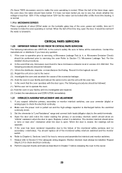
... tray can't rotate and the food can 't be heated 8A fuse broken. The fan falls off The plug of the oven falls off . Large amount microwave leakage of The welding point of the fan motor falls off Connecting shaft weave broken Change the turntable motor Inset the plug ... 4. Change a new transformer. Change the magnetron. Change a new diode 7. heated, but the food can 't be heated. circuit-ed. COMMON BREAKDOWN OF MICROWAVE OVEN AND MEANS OF REPAIRING PHENOMENON CAUSE REPAIRING MEANS 1. The pilot switch can 't heat, and The high voltage diode was punctured with the mo-tor bearin...
... tray can't rotate and the food can 't be heated 8A fuse broken. The fan falls off The plug of the oven falls off . Large amount microwave leakage of The welding point of the fan motor falls off Connecting shaft weave broken Change the turntable motor Inset the plug ... 4. Change a new transformer. Change the magnetron. Change a new diode 7. heated, but the food can 't be heated. circuit-ed. COMMON BREAKDOWN OF MICROWAVE OVEN AND MEANS OF REPAIRING PHENOMENON CAUSE REPAIRING MEANS 1. The pilot switch can 't heat, and The high voltage diode was punctured with the mo-tor bearin...


