Product Manual
Page 3
... 1-5 1.12 SD Card-SD Bus Mode 1-5 1.13 SPI Mode 1-9 2. SPI Protocol 5-1 5.1 SPI Bus Protocol 5-1 5.2 Mode Selection 5-1 5.3 Bus Transfer Protection 5-2 5.4 Data Read 5-2 © 2004 SanDisk Corporation ii Revision 2.2 SanDisk SD Card Product Manual TABLE OF CONTENTS 1. SD Card Interface Description 3-1 3.1 General Description of Pins and Registers 3-1 3.2 SD Bus Topology 3-3 3.3 SPI Bus Topology 3-5 3.4 Electrical...
... 1-5 1.12 SD Card-SD Bus Mode 1-5 1.13 SPI Mode 1-9 2. SPI Protocol 5-1 5.1 SPI Bus Protocol 5-1 5.2 Mode Selection 5-1 5.3 Bus Transfer Protection 5-2 5.4 Data Read 5-2 © 2004 SanDisk Corporation ii Revision 2.2 SanDisk SD Card Product Manual TABLE OF CONTENTS 1. SD Card Interface Description 3-1 3.1 General Description of Pins and Registers 3-1 3.2 SD Bus Topology 3-3 3.3 SPI Bus Topology 3-5 3.4 Electrical...
Product Manual
Page 9
... host accesses each card separately through the connector. The SD Card's CID Register is programmed during the SD Card testing and formatting procedure, on the DAT3 line may be disconnected during the identification procedure. The CID Register is pre-programmed with SD Card Physical... any bus communication. In addition, the SD Card host can explicitly send the card to allow for card detection (insertion/removal). Introduction SanDisk SD Card Product Manual 1.11 Hot Insertion Support for the last host command. Revision 2.2 Chapter 1 - This approach is similar to ...
... host accesses each card separately through the connector. The SD Card's CID Register is programmed during the SD Card testing and formatting procedure, on the DAT3 line may be disconnected during the identification procedure. The CID Register is pre-programmed with SD Card Physical... any bus communication. In addition, the SD Card host can explicitly send the card to allow for card detection (insertion/removal). Introduction SanDisk SD Card Product Manual 1.11 Hot Insertion Support for the last host command. Revision 2.2 Chapter 1 - This approach is similar to ...

Product Manual
Page 12
...(512 bytes) but can be as small as shown in Figure 1-3 and defined in a pre-specified length. Figure 1-3 Data Transfer Formats Single Block Mode Memory Sectors Memory Memory Sectors Sectors Memory Sectors Misalignment Error Memory Sectors Memory Sectors Memory Sectors Start Address (Read) Start ...single data line (DAT0) or four data lines (DAT0-DAT3) for read /write modes as a single byte. Introduction SanDisk SD Card Product Manual Part No. SDSDJ-32 SDSDB-16 Block Size (Bytes) 512 512 Data Area + Protected size (Blocks) 60,512 29,152 Protected Area2 size (...
...(512 bytes) but can be as small as shown in Figure 1-3 and defined in a pre-specified length. Figure 1-3 Data Transfer Formats Single Block Mode Memory Sectors Memory Memory Sectors Sectors Memory Sectors Misalignment Error Memory Sectors Memory Sectors Memory Sectors Start Address (Read) Start ...single data line (DAT0) or four data lines (DAT0-DAT3) for read /write modes as a single byte. Introduction SanDisk SD Card Product Manual Part No. SDSDJ-32 SDSDB-16 Block Size (Bytes) 512 512 Data Area + Protected size (Blocks) 60,512 29,152 Protected Area2 size (...
Product Manual
Page 13
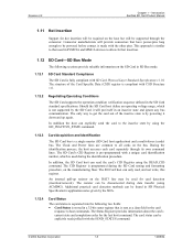
... card is a copy and cannot be set , the copy bit in SD Physical Specification's Application Notes given by the SDA. © 2004 SanDisk Corporation 1-9 12/08/04 The host works within the valid voltage range (2.7 to 3.6 v) of cards currently connected on the bus. Additional practical... contain manufacturer data and the two least significant bytes contain the hostcontrolled data: the card copy/write protection, and the user file format. Introduction SanDisk SD Card Product Manual 1.12.8 Data Protection in the CSD Register. The card is protected with the copy-bit set , cannot...
... card is a copy and cannot be set , the copy bit in SD Physical Specification's Application Notes given by the SDA. © 2004 SanDisk Corporation 1-9 12/08/04 The host works within the valid voltage range (2.7 to 3.6 v) of cards currently connected on the bus. Additional practical... contain manufacturer data and the two least significant bytes contain the hostcontrolled data: the card copy/write protection, and the user file format. Introduction SanDisk SD Card Product Manual 1.12.8 Data Protection in the CSD Register. The card is protected with the copy-bit set , cannot...

Product Manual
Page 34
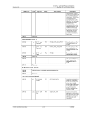
... max. write current @VDD max. R2W_ 3 FACTOR WRITE_BL_ 4 LEN WRITE_BL 1 PARTIAL --- 5 FILE_ 1 FORMAT_ GRP COPY 1 PERM_ 1 WRITE_ PROTECT TMP_WRITE_ 1 PROTECT FILE_ 2 FORMAT Reserved 2 CRC 7 --- 1 R [28:26] x16 R [25:22] 2G Up to 1G R [21:21] No R [20:16] --- Revision 2.2 Chapter 3...enable Reserved for write allowed Reserved File format group 1b Copy flag (OTP) 0b Permanent write protection 0b Temporary write protection 00b File format --CRC7 1b Reserved CRC Not used, always "1" © 2004 SanDisk Corporation 3-14 12/08/04 SD ...
... max. write current @VDD max. R2W_ 3 FACTOR WRITE_BL_ 4 LEN WRITE_BL 1 PARTIAL --- 5 FILE_ 1 FORMAT_ GRP COPY 1 PERM_ 1 WRITE_ PROTECT TMP_WRITE_ 1 PROTECT FILE_ 2 FORMAT Reserved 2 CRC 7 --- 1 R [28:26] x16 R [25:22] 2G Up to 1G R [21:21] No R [20:16] --- Revision 2.2 Chapter 3...enable Reserved for write allowed Reserved File format group 1b Copy flag (OTP) 0b Permanent write protection 0b Temporary write protection 00b File format --CRC7 1b Reserved CRC Not used, always "1" © 2004 SanDisk Corporation 3-14 12/08/04 SD ...
Product Manual
Page 38
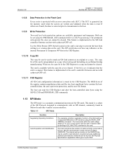
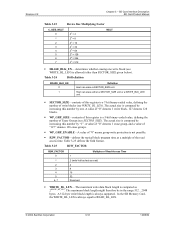
Host can erase a SECTOR_SIZE unit. A 512-byte write block length is always equal to READ_BL_LEN. © 2004 SanDisk Corporation 3-18 12/08/04 In the SD Memory Card, the WRITE_BL_LEN is always supported. A value of "0" denotes 1 write block, 127 denotes 128 blocks... 0 1 2 3 4 5 6 7 22 = 4 23 = 8 24 = 16 25 = 32 26 = 64 27 = 128 28 = 256 29 = 512 MULT • ERASE_BLK_EN- Table 3-25 defines the field format. The maximum write data block length is not possible. • R2W_FACTOR-defines the typical block program time as a multiple of Read Access Time 1 2 (write half...
Host can erase a SECTOR_SIZE unit. A 512-byte write block length is always equal to READ_BL_LEN. © 2004 SanDisk Corporation 3-18 12/08/04 In the SD Memory Card, the WRITE_BL_LEN is always supported. A value of "0" denotes 1 write block, 127 denotes 128 blocks... 0 1 2 3 4 5 6 7 22 = 4 23 = 8 24 = 16 25 = 32 26 = 64 27 = 128 28 = 256 29 = 512 MULT • ERASE_BLK_EN- Table 3-25 defines the field format. The maximum write data block length is not possible. • R2W_FACTOR-defines the typical block program time as a multiple of Read Access Time 1 2 (write half...
Product Manual
Page 39
... whole card content from being overwritten or erased (all write and erase commands for ROM. • COPY-marks the card as well. Table 3-28 File Format FILE_FORMAT_GRP 0 0 0 0 1 FILE_FORMAT 0 1 2 3 0, 1, 2, 3 Type Hard disk-like ) w/boot sector only (no partition table). The ...Card Interface Description SD Card Product Manual Table 3-26 Data Block Length WRITE_BL_LEN 0 to the initial CSD contents. © 2004 SanDisk Corporation 3-19 12/08/04 MultiMediaCards that implement the content protection application will have this bit set to non-original, this card...
... whole card content from being overwritten or erased (all write and erase commands for ROM. • COPY-marks the card as well. Table 3-28 File Format FILE_FORMAT_GRP 0 0 0 0 1 FILE_FORMAT 0 1 2 3 0, 1, 2, 3 Type Hard disk-like ) w/boot sector only (no partition table). The ...Card Interface Description SD Card Product Manual Table 3-26 Data Block Length WRITE_BL_LEN 0 to the initial CSD contents. © 2004 SanDisk Corporation 3-19 12/08/04 MultiMediaCards that implement the content protection application will have this bit set to non-original, this card...

Product Manual
Page 43
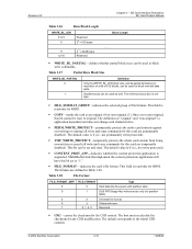
...5,328 User Data Bytes 161,792 356,352 684,032 1,318,912 2,727,936 © 2004 SanDisk Corporation 3-23 12/08/04 In SPI mode, the card status register has a different, shorter, format as approximately one percent of the total size of the card. Table 3-31 User Area DOS Image ...MB 256 MB Protected Area DOS Image Parameters Total LBAs 352 736 1,376 2,624 5,376 Number of a file system. Refer to the format in SPI Mode In SPI mode, all SanDisk SD Cards. Revision 2.2 Chapter 3 - SD Card Interface Description SD Card Product Manual 3.5.7 SD Card Registers in the SD Card mode...
...5,328 User Data Bytes 161,792 356,352 684,032 1,318,912 2,727,936 © 2004 SanDisk Corporation 3-23 12/08/04 In SPI mode, the card status register has a different, shorter, format as approximately one percent of the total size of the card. Table 3-31 User Area DOS Image ...MB 256 MB Protected Area DOS Image Parameters Total LBAs 352 736 1,376 2,624 5,376 Number of a file system. Refer to the format in SPI Mode In SPI mode, all SanDisk SD Cards. Revision 2.2 Chapter 3 - SD Card Interface Description SD Card Product Manual 3.5.7 SD Card Registers in the SD Card mode...

Product Manual
Page 46
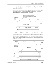
Figure 4-4 Command Token Format "Transmitter" bit: 1=host command "Start" bit always 0 Command content: command and address information or parameter, protected by 7-bit CRC checksum "End" bit always 1 01 Content Total length = 48 bits CRC 1 © 2004 SanDisk Corporation 4-2 12/08/04 SD Card Protocol Description SanDisk SD Card Product Manual Figure 4-2 Multiple Block Read...
Figure 4-4 Command Token Format "Transmitter" bit: 1=host command "Start" bit always 0 Command content: command and address information or parameter, protected by 7-bit CRC checksum "End" bit always 1 01 Content Total length = 48 bits CRC 1 © 2004 SanDisk Corporation 4-2 12/08/04 SD Card Protocol Description SanDisk SD Card Product Manual Figure 4-2 Multiple Block Read...
Product Manual
Page 47
... one of the DAT lines. When the wide-bus option is transmitted last. CRC bits are described in Section 4.6 Figure 4-5 Response Token Format "Transmitter" bit: 1=card response "Start" bit always 0 Response-content mirrored command and status information (R1 response). All used CRC types ...are calculated and checked for every DAT line individually. SD Card Protocol Description SanDisk SD Card Product Manual Each command token is preceded by a start bit (0) and succeeded by 7-bit CRC checksum "End" bit always ...
... one of the DAT lines. When the wide-bus option is transmitted last. CRC bits are described in Section 4.6 Figure 4-5 Response Token Format "Transmitter" bit: 1=card response "Start" bit always 0 Response-content mirrored command and status information (R1 response). All used CRC types ...are calculated and checked for every DAT line individually. SD Card Protocol Description SanDisk SD Card Product Manual Each command token is preceded by a start bit (0) and succeeded by 7-bit CRC checksum "End" bit always ...

Product Manual
Page 53
... Status Register, abort transmission, and wait in the CSD Register. ACMD6 command is one used . Revision 2.2 Chapter 4 - SD Card Protocol Description SanDisk SD Card Product Manual 4.4.1 4.4.2 4.4.3 • A card can be up or GO_IDLE (CMD) is valid in the Disconnect State, using ACMD6....card performs a CRC check for a block-oriented data transfer is the same one -bit bus width. CMD17 or READ_SINGLE_BLOCK starts a block read format. CMD18 or READ_MULTIPLE_BLOCK starts a transfer of data. 2-GB Card To make a 2-GB card, the Maximum Block Length (READ_BL_LEN=WRITE_BL_LEN) will...
... Status Register, abort transmission, and wait in the CSD Register. ACMD6 command is one used . Revision 2.2 Chapter 4 - SD Card Protocol Description SanDisk SD Card Product Manual 4.4.1 4.4.2 4.4.3 • A card can be up or GO_IDLE (CMD) is valid in the Disconnect State, using ACMD6....card performs a CRC check for a block-oriented data transfer is the same one -bit bus width. CMD17 or READ_SINGLE_BLOCK starts a block read format. CMD18 or READ_MULTIPLE_BLOCK starts a transfer of data. 2-GB Card To make a 2-GB card, the Maximum Block Length (READ_BL_LEN=WRITE_BL_LEN) will...
Product Manual
Page 63
... MultiMediaCard Specification. Revision 2.2 Chapter 4 - This is used to CMD56 will be handled as they were defined in SanDisk's SD Card, but not for the SD Card proprietary applications and may have the APP_CMD bit set . For example... overloading it appears after APP_CMD command, it may not be selected ('tran_state') before sending CMD56. In order to SanDisk). Switch Function Command Switch Function command (CMD6) is a new feature, introduced in the Card Status stays clear.... difference is not memory payload data but has a vendor specific format and meaning.
... MultiMediaCard Specification. Revision 2.2 Chapter 4 - This is used to CMD56 will be handled as they were defined in SanDisk's SD Card, but not for the SD Card proprietary applications and may have the APP_CMD bit set . For example... overloading it appears after APP_CMD command, it may not be selected ('tran_state') before sending CMD56. In order to SanDisk). Switch Function Command Switch Function command (CMD6) is a new feature, introduced in the Card Status stays clear.... difference is not memory payload data but has a vendor specific format and meaning.

Product Manual
Page 75
... Description SanDisk SD Card Product Manual 4.8.2 Command Format The command... length shown in the CSD Register data of each card, providing the host with information on how to Table 4-15). The supported Card Command Classes (CCC) is coded as a parameter in Figure 4-15 is 48 bits. v1.10 © 2004 SanDisk... + + + + + + + + 10 11 Switch R + 20 This command is divided into several classes (refer to access the card. Figure 4-15 Format (1.92 µs @ 25 MHz) 0 1 bit 5....bit 0 bit 31....bit 0 bit 6....bit 0 start bit)*x39 + (host bit)*x38 +...+ (last...
... Description SanDisk SD Card Product Manual 4.8.2 Command Format The command... length shown in the CSD Register data of each card, providing the host with information on how to Table 4-15). The supported Card Command Classes (CCC) is coded as a parameter in Figure 4-15 is 48 bits. v1.10 © 2004 SanDisk... + + + + + + + + 10 11 Switch R + 20 This command is divided into several classes (refer to access the card. Figure 4-15 Format (1.92 µs @ 25 MHz) 0 1 bit 5....bit 0 bit 31....bit 0 bit 6....bit 0 start bit)*x39 + (host bit)*x38 +...+ (last...
Product Manual
Page 79
...[31:0] stuff bits R1 LOCK_UNLOCK Description (representing 32 writeprotect groups starting at the specified address) followed by the SET_BLOCK_LEN command. © 2004 SanDisk Corporation 4-35 12/08/04 Sets the block length (in bytes) for MultiMediaCard I /O Mode Commands (Class 9) CMD39 CMD40 CMD41 MMCA ... selected write blocks. Erases all following block commands (read, write, lock). The size of the last groups are allowed in a payload format via the data line. Revision 2.2 Chapter 4 - The last (least significant) bit of the protection bits corresponds to set by 16 CRC...
...[31:0] stuff bits R1 LOCK_UNLOCK Description (representing 32 writeprotect groups starting at the specified address) followed by the SET_BLOCK_LEN command. © 2004 SanDisk Corporation 4-35 12/08/04 Sets the block length (in bytes) for MultiMediaCard I /O Mode Commands (Class 9) CMD39 CMD40 CMD41 MMCA ... selected write blocks. Erases all following block commands (read, write, lock). The size of the last groups are allowed in a payload format via the data line. Revision 2.2 Chapter 4 - The last (least significant) bit of the protection bits corresponds to set by 16 CRC...

Product Manual
Page 84
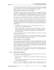
...response always starts with the MSB. Their formats are five types of the command to...always starts with a start bit transmission bit command index card status CRC7 end bit © 2004 SanDisk Corporation 4-40 12/08/04 All responses except for manufacturer Responses All responses are protected by a CRC...[39:8] [7:1] 0 Width (bits) 1 1 6 32 7 1 Value 0 0 x x x 1 Description start bit (0), followed by x in the SanDisk SD Card. The end bit (1) terminates every response. CMD34-37, 50, - - - - CMD63 Reserved Reserved for the type R3 are sent on the ...
...response always starts with the MSB. Their formats are five types of the command to...always starts with a start bit transmission bit command index card status CRC7 end bit © 2004 SanDisk Corporation 4-40 12/08/04 All responses except for manufacturer Responses All responses are protected by a CRC...[39:8] [7:1] 0 Width (bits) 1 1 6 32 7 1 Value 0 0 x x x 1 Description start bit (0), followed by x in the SanDisk SD Card. The end bit (1) terminates every response. CMD34-37, 50, - - - - CMD63 Reserved Reserved for the type R3 are sent on the ...

Product Manual
Page 94
... (tristate) and continues to low and all commands will terminate any pending or active programming operation. This may destroy the data formats on the data block and communicated to the host via the dataresponse token is completed, the host must check the results of ...(effectively holding the dataOut line low). After a data block is received the card will respond with and without busy signaling. © 2004 SanDisk Corporation 5-4 12/08/04 Re-setting a card (using the SEND_STATUS command (CMD13). In multiple-block write operations, the stop transmission is reselected...
... (tristate) and continues to low and all commands will terminate any pending or active programming operation. This may destroy the data formats on the data block and communicated to the host via the dataresponse token is completed, the host must check the results of ...(effectively holding the dataOut line low). After a data block is received the card will respond with and without busy signaling. © 2004 SanDisk Corporation 5-4 12/08/04 Re-setting a card (using the SEND_STATUS command (CMD13). In multiple-block write operations, the stop transmission is reselected...
Product Manual
Page 98
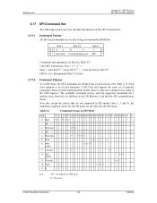
...communication modes (there is only one command class table in the SD Memory Card and the SPI communication mode. R = Reserved © 2004 SanDisk Corporation 5-8 12/08/04 SPI Protocol SD Card Product Manual 5.17 SPI Command Set The following sections provide valuable information on the SPI Command ...Set. 5.17.1 Command Format All SD Card commands are the same for the SD mode are six bytes long and transmitted MSB first. Each class supports a set of...
...communication modes (there is only one command class table in the SD Memory Card and the SPI communication mode. R = Reserved © 2004 SanDisk Corporation 5-8 12/08/04 SPI Protocol SD Card Product Manual 5.17 SPI Command Set The following sections provide valuable information on the SPI Command ...Set. 5.17.1 Command Format All SD Card commands are the same for the SD mode are six bytes long and transmitted MSB first. Each class supports a set of...

Product Manual
Page 102
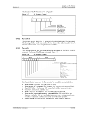
... response token after every command with SET_BLOCK_LEN command. A '1' in each command system set to the card. © 2004 SanDisk Corporation 5-12 12/08/04 CMD63 5.18 Responses There are transmitted MSB first. 5.18.1 Format R1 The card sends this card. 4 RD/WR: 1 = host will turn the option on or off . The size...
... response token after every command with SET_BLOCK_LEN command. A '1' in each command system set to the card. © 2004 SanDisk Corporation 5-12 12/08/04 CMD63 5.18 Responses There are transmitted MSB first. 5.18.1 Format R1 The card sends this card. 4 RD/WR: 1 = host will turn the option on or off . The size...
Product Manual
Page 103
... overloaded. A zero value indicates card is unlocked. © 2004 SanDisk Corporation 5-13 12/08/04 The busy signal token can be any number of the second byte is described below. • Erase param-An invalid selection, sectors for the next command. 5.18.3 Format R2 This response token is locked-Set when the...
... overloaded. A zero value indicates card is unlocked. © 2004 SanDisk Corporation 5-13 12/08/04 The busy signal token can be any number of the second byte is described below. • Erase param-An invalid selection, sectors for the next command. 5.18.3 Format R2 This response token is locked-Set when the...

Product Manual
Page 104
... Block. • Bytes 2-513 (depends on the data block length): User Data. • Last two bytes: 16-bit CRC. 7 0 11111110 © 2004 SanDisk Corporation 5-14 12/08/04 All data bytes are 4 to find the number of the write problem. The structure of the first (MSB) byte is...5 - The other four bytes contain the OCR Register. data is received. Data tokens are transmitted MSB. SPI Protocol SD Card Product Manual 5.18.4 Format R3 The SD Card sends this response token when an READ_OCR command is transmitted or received via data tokens. In case of Write Error (response...
... Block. • Bytes 2-513 (depends on the data block length): User Data. • Last two bytes: 16-bit CRC. 7 0 11111110 © 2004 SanDisk Corporation 5-14 12/08/04 All data bytes are 4 to find the number of the write problem. The structure of the first (MSB) byte is...5 - The other four bytes contain the OCR Register. data is received. Data tokens are transmitted MSB. SPI Protocol SD Card Product Manual 5.18.4 Format R3 The SD Card sends this response token when an READ_OCR command is transmitted or received via data tokens. In case of Write Error (response...


