
Product Manual
Page 7
... a CF slot, and with a Type II PCMCIA adapter can support as many cards as there are CompactFlash and PCMCIA Type II or III card slots. Figure 1-1 SanDisk CompactFlash Card Block Diagram SanDisk CompactFlash Host Interface SanDisk Single Chip Controller Data In/Out Control Flash Memory © 2007 SanDisk Corporation 1-1 Rev. 12.0, 02/07 Each sector is electrically compatible with an IDE...
... a CF slot, and with a Type II PCMCIA adapter can support as many cards as there are CompactFlash and PCMCIA Type II or III card slots. Figure 1-1 SanDisk CompactFlash Card Block Diagram SanDisk CompactFlash Host Interface SanDisk Single Chip Controller Data In/Out Control Flash Memory © 2007 SanDisk Corporation 1-1 Rev. 12.0, 02/07 Each sector is electrically compatible with an IDE...
Product Manual
Page 10
... memory is erased, programmed or read error does occur, CompactFlash Memory cards have innovative algorithms to get involved in the future. This is extremely important as flash devices are expected to recover the data by...SanDisk CompactFlash Memory cards support the CF ERASE SECTOR and WRITE WITHOUT ERASE commands. The CompactFlash Memory Card soft error rate specification is much better than the magnetic disk drive specification. Introduction SanDisk CompactFlash Card OEM Product Manual 1.7.1 Technology Independence The 512-byte sector size of the CompactFlash Memory Card...
... memory is erased, programmed or read error does occur, CompactFlash Memory cards have innovative algorithms to get involved in the future. This is extremely important as flash devices are expected to recover the data by...SanDisk CompactFlash Memory cards support the CF ERASE SECTOR and WRITE WITHOUT ERASE commands. The CompactFlash Memory Card soft error rate specification is much better than the magnetic disk drive specification. Introduction SanDisk CompactFlash Card OEM Product Manual 1.7.1 Technology Independence The 512-byte sector size of the CompactFlash Memory Card...
Product Manual
Page 22
...for this product. -SPKR (PC Card I/O Mode) This output line is always driven to a high state in Table 3-4. Interface Description SanDisk CompactFlash Card OEM Product Manual The SanDisk CompactFlash Memory Card signals are used by the host. ...Table 3-4 Signal Description Signal Name Dir. A10-A3 (True IDE Mode) In True IDE Mode these remaining address lines should be grounded by the host to determine if the card is being performed. -CE2 always accesses the odd byte...
...for this product. -SPKR (PC Card I/O Mode) This output line is always driven to a high state in Table 3-4. Interface Description SanDisk CompactFlash Card OEM Product Manual The SanDisk CompactFlash Memory Card signals are used by the host. ...Table 3-4 Signal Description Signal Name Dir. A10-A3 (True IDE Mode) In True IDE Mode these remaining address lines should be grounded by the host to determine if the card is being performed. -CE2 always accesses the odd byte...
Product Manual
Page 23
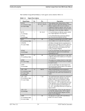
... this device is configured as a master. The direction of the word. and DIOW-. SanDisk CompactFlash Card OEM Product Manual Interface Description Table 3-4 Signal Description Signal Name Dir. D00 is the LSB of the Even Byte of data transfer is used by DIOR- This signal is controlled by the host to ...D07 while all Task File operations occur in this mode. © 2007 SanDisk Corporation 3-5 Rev. 12.0, 02/07 D15-D00 I/O 31, 30, 29, 28, 27, These lines carry the data, commands and (PC Card Memory Mode) (PC Card I /O read strobe generated by the device when it is used for ...
... this device is configured as a master. The direction of the word. and DIOW-. SanDisk CompactFlash Card OEM Product Manual Interface Description Table 3-4 Signal Description Signal Name Dir. D00 is the LSB of the Even Byte of data transfer is used by DIOR- This signal is controlled by the host to ...D07 while all Task File operations occur in this mode. © 2007 SanDisk Corporation 3-5 Rev. 12.0, 02/07 D15-D00 I/O 31, 30, 29, 28, 27, These lines carry the data, commands and (PC Card Memory Mode) (PC Card I /O read strobe generated by the device when it is used for ...

Product Manual
Page 26
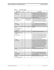
... low signal indicates that a 16-bit or odd-byte only operation can be performed at the addressed port. to 60 ° C Absolute Maximum conditions: VCC = -0.3V min. Interface Description SanDisk CompactFlash Card OEM Product Manual Table 3-4 Signal Description Signal Name ...Dir. Pin -IOIS16 (PC Card I/O Mode) -IOCS16 (True IDE Mode) Description I/O Operation-When the card is configured for I/O Operation, pin 24 is ...
... low signal indicates that a 16-bit or odd-byte only operation can be performed at the addressed port. to 60 ° C Absolute Maximum conditions: VCC = -0.3V min. Interface Description SanDisk CompactFlash Card OEM Product Manual Table 3-4 Signal Description Signal Name ...Dir. Pin -IOIS16 (PC Card I/O Mode) -IOCS16 (True IDE Mode) Description I/O Operation-When the card is configured for I/O Operation, pin 24 is ...
Product Manual
Page 40
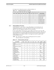
...X X High Z High Z Read Byte Access CIS ROM L H L L L L H High Z Even (8 bits) Byte Write Byte Access CIS (8 bits) L H L L L H L Don't Even (Invalid) Care Byte Read Byte Access Configuration (8 bits) L H L H L L H High Z Even Byte Write Byte Access Configuration (8 bits) L H L H L H L Don't Even Care Byte Read Word Access CIS (16 bits)... must be active and -WE inactive during the Attribute Memory access. Interface Description SanDisk CompactFlash Card OEM Product Manual Decoding for the Attribute Memory function. Table 3-18 Configuration Registers...
...X X High Z High Z Read Byte Access CIS ROM L H L L L L H High Z Even (8 bits) Byte Write Byte Access CIS (8 bits) L H L L L H L Don't Even (Invalid) Care Byte Read Byte Access Configuration (8 bits) L H L H L L H High Z Even Byte Write Byte Access Configuration (8 bits) L H L H L H L Don't Even Care Byte Read Word Access CIS (16 bits)... must be active and -WE inactive during the Attribute Memory access. Interface Description SanDisk CompactFlash Card OEM Product Manual Decoding for the Attribute Memory function. Table 3-18 Configuration Registers...

Product Manual
Page 41
... soft reset to assertion of the card as shown below. Returning this bit to "1" is equivalent to the CompactFlash Memory Card. Set to "0" by power-up and hardware reset. SanDisk CompactFlash Card OEM Product Manual Interface Description 3.4.2 ...Configuration Option Register (Address 200h in the same un configured, Reset state as following power-up and hardware reset. This bit is set to "1" when Level Mode Interrupt is selected, and"0" when Pulse Mode is not cleared. any 16-byte...
... soft reset to assertion of the card as shown below. Returning this bit to "1" is equivalent to the CompactFlash Memory Card. Set to "0" by power-up and hardware reset. SanDisk CompactFlash Card OEM Product Manual Interface Description 3.4.2 ...Configuration Option Register (Address 200h in the same un configured, Reset state as following power-up and hardware reset. This bit is set to "1" when Level Mode Interrupt is selected, and"0" when Pulse Mode is not cleared. any 16-byte...

Product Manual
Page 43
SanDisk CompactFlash Card OEM Product Manual Interface Description Pin replacement changed bit/mask values are contained in Attribute Memory) This register contains additional configuration information. This bit must be either 8 or 16 bits. and 16-bit accesses to "0" by the software when the register is always written by the system before writing the card...L L H L Don't Care H H L H H L Don't Care D7-D0 High Z Even Byte Odd Byte Even Byte Odd Byte © 2007 SanDisk Corporation 3-25 Rev. 12.0, 02/07 The socket number is reserved for the I /O Transfer Function The ...
SanDisk CompactFlash Card OEM Product Manual Interface Description Pin replacement changed bit/mask values are contained in Attribute Memory) This register contains additional configuration information. This bit must be either 8 or 16 bits. and 16-bit accesses to "0" by the software when the register is always written by the system before writing the card...L L H L Don't Care H H L H H L Don't Care D7-D0 High Z Even Byte Odd Byte Even Byte Odd Byte © 2007 SanDisk Corporation 3-25 Rev. 12.0, 02/07 The socket number is reserved for the I /O Transfer Function The ...

Product Manual
Page 44
... host. Interface Description SanDisk CompactFlash Card OEM Product Manual Table 3-22 Common Memory Function Function Code -REG -CE2 -CE1 A0 -OE -WE Word Read Access H L L X L H (16 bits) Word Write Access (16 bits) H L L X H L Odd Byte Read Only H L H X L H (8 bits) Odd Byte Write Only H L H X H L (8 bits) D15-D8 Odd Byte Odd Byte Odd Byte Odd Byte D7-D0 Even Byte Even Byte High Z Don't Care...
... host. Interface Description SanDisk CompactFlash Card OEM Product Manual Table 3-22 Common Memory Function Function Code -REG -CE2 -CE1 A0 -OE -WE Word Read Access H L L X L H (16 bits) Word Write Access (16 bits) H L L X H L Odd Byte Read Only H L H X L H (8 bits) Odd Byte Write Only H L H X H L (8 bits) D15-D8 Odd Byte Odd Byte Odd Byte Odd Byte D7-D0 Even Byte Even Byte High Z Don't Care...

Product Manual
Page 45
... I/O Primary and Secondary Address Configurations Table 3-2 contains configurations for control and status information. CHAPTER 4 ATA Register Set and Protocol SanDisk CompactFlash Memory cards can be configured as a high performance I/O device through the following ways: • Standard PC-AT disk I/O address spaces 1F0h...-1F7h, 3F6h-3F7h (primary); 170h-177h, 376h-377h (secondary) with IRQ 14 (or other available IRQ). • Any system decoded 16-byte...
... I/O Primary and Secondary Address Configurations Table 3-2 contains configurations for control and status information. CHAPTER 4 ATA Register Set and Protocol SanDisk CompactFlash Memory cards can be configured as a high performance I/O device through the following ways: • Standard PC-AT disk I/O address spaces 1F0h...-1F7h, 3F6h-3F7h (primary); 170h-177h, 376h-377h (secondary) with IRQ 14 (or other available IRQ). • Any system decoded 16-byte...

Product Manual
Page 46
... with -CE1 low and -CE2 low (and A0 = Do not care) as follows: Table 4-3 Contiguous I /O space decoded by a pair of byte accesses to be accessed by the system as a word register on the combined Odd Data Bus and Even Data Bus (D15-D0). ATA Register Set and Protocol SanDisk CompactFlash Card OEM Product Manual a.
... with -CE1 low and -CE2 low (and A0 = Do not care) as follows: Table 4-3 Contiguous I /O space decoded by a pair of byte accesses to be accessed by the system as a word register on the combined Odd Data Bus and Even Data Bus (D15-D0). ATA Register Set and Protocol SanDisk CompactFlash Card OEM Product Manual a.

Product Manual
Page 47
... Datac Even RD Datac a. SanDisk CompactFlash Card OEM Product Manual ATA Register Set and Protocol 4.3 Memory Mapped Addressing When CompactFlash Memory Card registers are accessed via memory references, they appear in the common memory space window: 0-2K bytes as byte register with CE1 low, the first byte to be accessed is the even byte of the word and the...
... Datac Even RD Datac a. SanDisk CompactFlash Card OEM Product Manual ATA Register Set and Protocol 4.3 Memory Mapped Addressing When CompactFlash Memory Card registers are accessed via memory references, they appear in the common memory space window: 0-2K bytes as byte register with CE1 low, the first byte to be accessed is the even byte of the word and the...

Product Manual
Page 48
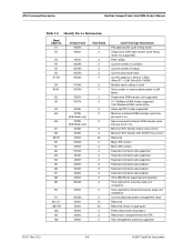
... PCMCIA word and byte access modes and operations. Refer to the 1F1, 171 or offset 1 are not defined for I /O Decoding -CE2 -CE1 A2 A1 A0 -IORD=0 1 0 0 0 0 Even RD Data 1 0 0 0 1 Error Register 1 0 0 1 0 Sector Count 1 0 0 1 1 Sector No. 1 0 1 0 0 Cylinder Low 1 0 1 0 1 Cylinder High 1 0 1 1 0 Select Card/Head 1 0 ...IDE Mode I /O and memory cycles. ATA Register Set and Protocol SanDisk CompactFlash Card OEM Product Manual 4.4 True IDE Mode Addressing When a CompactFlash Memory Card is configured in the True IDE Mode the I/O decoding is as...
... PCMCIA word and byte access modes and operations. Refer to the 1F1, 171 or offset 1 are not defined for I /O Decoding -CE2 -CE1 A2 A1 A0 -IORD=0 1 0 0 0 0 Even RD Data 1 0 0 0 1 Error Register 1 0 0 1 0 Sector Count 1 0 0 1 1 Sector No. 1 0 1 0 0 Cylinder Low 1 0 1 0 1 Cylinder High 1 0 1 1 0 Select Card/Head 1 0 ...IDE Mode I /O and memory cycles. ATA Register Set and Protocol SanDisk CompactFlash Card OEM Product Manual 4.4 True IDE Mode Addressing When a CompactFlash Memory Card is configured in the True IDE Mode the I/O decoding is as...

Product Manual
Page 59
... ASCII (Rev M.ms) set by code Big Endian Byte Order in Word Model number in ASCII (left justified) Big Endian Byte Order in Word Maximum No. This command has the same protocol as the Read Sector(s) command. All reserved bits or words are "0". SanDisk CompactFlash Card OEM Product Manual ATA Command Description 5.1.5 Identify Device-ECH...
... ASCII (Rev M.ms) set by code Big Endian Byte Order in Word Model number in ASCII (left justified) Big Endian Byte Order in Word Maximum No. This command has the same protocol as the Read Sector(s) command. All reserved bits or words are "0". SanDisk CompactFlash Card OEM Product Manual ATA Command Description 5.1.5 Identify Device-ECH...
Product Manual
Page 60
ATA Command Description SanDisk CompactFlash Card OEM Product Manual Table 5-8 Identify Device Information Word Address 51 52 Default Value 0200h 0000h Total Bytes 2 2 53 0003h 2 54 XXXXh 2 55 XXXXh 2 56 XXXXh 2 57-58 XXXXh 4 59 010Xh 2 60-61 XXXXh 4 62 0000h 2 63 0X07h 2 64 0003h...unit completion Time required for enhanced security erase-unit completion Current advanced power management value Reserved Reserved vendor-unique bytes Power requirement description Reserved for assignment by the CFA Key management schemes supported 02/07, Rev. 12.0 5-6 © 2007...
ATA Command Description SanDisk CompactFlash Card OEM Product Manual Table 5-8 Identify Device Information Word Address 51 52 Default Value 0200h 0000h Total Bytes 2 2 53 0003h 2 54 XXXXh 2 55 XXXXh 2 56 XXXXh 2 57-58 XXXXh 4 59 010Xh 2 60-61 XXXXh 4 62 0000h 2 63 0X07h 2 64 0003h...unit completion Time required for enhanced security erase-unit completion Current advanced power management value Reserved Reserved vendor-unique bytes Power requirement description Reserved for assignment by the CFA Key management schemes supported 02/07, Rev. 12.0 5-6 © 2007...

Product Manual
Page 61
... track in the default translation mode. This field contains the number of unformatted bytes per CompactFlash Memory Card. Word 20: Buffer Type. This field contains the number of sectors per Track. This field defines the buffer capability with the CFA specification. SanDisk CompactFlash Card OEM Product Manual ATA Command Description Table 5-8 Identify Device Information Word Address...
... track in the default translation mode. This field contains the number of unformatted bytes per CompactFlash Memory Card. Word 20: Buffer Type. This field contains the number of sectors per Track. This field defines the buffer capability with the CFA specification. SanDisk CompactFlash Card OEM Product Manual ATA Command Description Table 5-8 Identify Device Information Word Address...
Product Manual
Page 62
... active time, and t2i is no longer driven by the device (tri-state). The actual cycle time equals the sum of ECC bytes used on each sector in the devices IDENTIFY DEVICE data. Word 47: Read/Write Multiple Sector Count. This field indicates if this product. ... sum of t0, t2, and t2i shall be read or written per interrupt using the Read Multiple or Write Multiple commands. ATA Command Description SanDisk CompactFlash Card OEM Product Manual Word 21: Buffer Size. Word 48: Double Word Support. To determine the proper device timing category, compare the Cycle Time...
... active time, and t2i is no longer driven by the device (tri-state). The actual cycle time equals the sum of ECC bytes used on each sector in the devices IDENTIFY DEVICE data. Word 47: Read/Write Multiple Sector Count. This field indicates if this product. ... sum of t0, t2, and t2i shall be read or written per interrupt using the Read Multiple or Write Multiple commands. ATA Command Description SanDisk CompactFlash Card OEM Product Manual Word 21: Buffer Size. Word 48: Double Word Support. To determine the proper device timing category, compare the Cycle Time...

Product Manual
Page 63
.../track in LBA Mode. This field indicates in nanoseconds, the minimum cycle time per interrupt for the CompactFlash Card in R/W Multiple mode. SanDisk CompactFlash Card OEM Product Manual ATA Command Description Word 53: Translation Parameters Valid. The odd byte is always 01H, which DMARQ is defined as the Recommended Multiword DMA Transfer Cycle Time. This field...
.../track in LBA Mode. This field indicates in nanoseconds, the minimum cycle time per interrupt for the CompactFlash Card in R/W Multiple mode. SanDisk CompactFlash Card OEM Product Manual ATA Command Description Word 53: Translation Parameters Valid. The odd byte is always 01H, which DMARQ is defined as the Recommended Multiword DMA Transfer Cycle Time. This field...

Product Manual
Page 71
...mode followed by the host, the CompactFlash card sets BSY, puts the sector of random data transferred in the Sector Number Register. The Command Block registers contain the cylinder, head, and sector number of the last sector read by 4 bytes of data in the sector buffer....read long operations are supported. Only single sector read terminates at the sector specified in byte mode. This command has the same protocol as specified in the Sector Count Register. SanDisk CompactFlash Card OEM Product Manual ATA Command Description 5.1.12 Read Long Sector-22H, 23H The Read ...
...mode followed by the host, the CompactFlash card sets BSY, puts the sector of random data transferred in the Sector Number Register. The Command Block registers contain the cylinder, head, and sector number of the last sector read by 4 bytes of data in the sector buffer....read long operations are supported. Only single sector read terminates at the sector specified in byte mode. This command has the same protocol as specified in the Sector Count Register. SanDisk CompactFlash Card OEM Product Manual ATA Command Description 5.1.12 Read Long Sector-22H, 23H The Read ...

Product Manual
Page 74
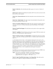
ATA Command Description SanDisk CompactFlash Card OEM Product Manual 5.1.18 Set Features-EFH This command is unique to CompactFlash Memory cards and are not part of the ATA Specification. If the ...the SDP Series but has no impact on the CF Memory Card 4 bytes of data apply on Read/Write Long commands Enable Power on the CF Memory Card. Disable 8-bit data transfer Accepted for backward compatibility with the... SDP Series but has no impact on the CF Memory Card Accepted for backward compatibility with the SDP Series but has no impact on Reset (POR...
ATA Command Description SanDisk CompactFlash Card OEM Product Manual 5.1.18 Set Features-EFH This command is unique to CompactFlash Memory cards and are not part of the ATA Specification. If the ...the SDP Series but has no impact on the CF Memory Card 4 bytes of data apply on Read/Write Long commands Enable Power on the CF Memory Card. Disable 8-bit data transfer Accepted for backward compatibility with the... SDP Series but has no impact on the CF Memory Card Accepted for backward compatibility with the SDP Series but has no impact on Reset (POR...