
Service Manual
Page 1
... Back Light Adjustment Function ¨ Digital Power Supply Synchronization Method ˆ DAY/NIGHT CAMERA (SCC-B2391(P)/SCC-B2091P/SCC-B2300) SCC-B2391(P)/SCC-B2091P/SCC-1391(P)/SCC-B1091P/SCC-B2300 This Service Manual is a property of Manual can be punished under applicable International and/or domestic law. © Samsung Electronics Co., Ltd. JUL. 2005 Printed in Korea MF82-00192A Any unauthorized use...
... Back Light Adjustment Function ¨ Digital Power Supply Synchronization Method ˆ DAY/NIGHT CAMERA (SCC-B2391(P)/SCC-B2091P/SCC-B2300) SCC-B2391(P)/SCC-B2091P/SCC-1391(P)/SCC-B1091P/SCC-B2300 This Service Manual is a property of Manual can be punished under applicable International and/or domestic law. © Samsung Electronics Co., Ltd. JUL. 2005 Printed in Korea MF82-00192A Any unauthorized use...

Service Manual
Page 12
Select the RS-232. - 3. RS232/RS485 Jig Board : This is a connection cable of the camera and the adjustment jig. - Before starting the adjustment process, OFF the Switch ! (L/L Switch) on the Rear board. Samsung Electronics 3-1 Camera I Port T Camea Side Camera Side round ig. RS232C Cable : This cable is the adjustment Jig Board. Alignment and Adjustment 3-1 Ca...
Select the RS-232. - 3. RS232/RS485 Jig Board : This is a connection cable of the camera and the adjustment jig. - Before starting the adjustment process, OFF the Switch ! (L/L Switch) on the Rear board. Samsung Electronics 3-1 Camera I Port T Camea Side Camera Side round ig. RS232C Cable : This cable is the adjustment Jig Board. Alignment and Adjustment 3-1 Ca...

Service Manual
Page 18
ig. * If blemish compensation process ends abnormally, message as below will be pop up , close the camera iris and click OK button. ig. message pops up . Samsung Electronics Alignment and Ad ustment ig. * After blemish compensation process finishes normally, message as below will be pop up. 6. If "Close the IRIS!" In this case, check the connection and try again from step 5.
ig. * If blemish compensation process ends abnormally, message as below will be pop up , close the camera iris and click OK button. ig. message pops up . Samsung Electronics Alignment and Ad ustment ig. * After blemish compensation process finishes normally, message as below will be pop up. 6. If "Close the IRIS!" In this case, check the connection and try again from step 5.

Service Manual
Page 19
Measuring tools : DVM(FLUKE87) or Oscilloscope. 3. Alignment and Ad ustment 3-2 PLL Voltage Adjustment 1. ig. Adjustment Spec : 2.5V ±0.2V. 4. Samsung Electronics Connect the AC Adaptor withe Camera Voltage frequency: NTSC (60Hz), PAL (50Hz). @ Switch on TP101 and rotate the Trimmer Condenser(C130). * PLL voltage adjustment is available only when EEPROM has proper data. Adjustment Process : Place the Probe on the Switch ! (L/L Switch) of the rear board. 2. Preparing !
Measuring tools : DVM(FLUKE87) or Oscilloscope. 3. Alignment and Ad ustment 3-2 PLL Voltage Adjustment 1. ig. Adjustment Spec : 2.5V ±0.2V. 4. Samsung Electronics Connect the AC Adaptor withe Camera Voltage frequency: NTSC (60Hz), PAL (50Hz). @ Switch on TP101 and rotate the Trimmer Condenser(C130). * PLL voltage adjustment is available only when EEPROM has proper data. Adjustment Process : Place the Probe on the Switch ! (L/L Switch) of the rear board. 2. Preparing !

Service Manual
Page 28
TroubleShootiong hen the power is a normal SCC-B2391(P)/B1391(P)/B2300 Is power connected correctly YES oes SE wor normally YES oes C of Power board output , normally YES oes C output of AI board normally YES oes ... , , PT of the P E NO A and chec the in/output flow of EA . eplace it if necessary. Chec the connection between A APT NO and Camera. eplace it if necessary. Samsung Electronics 5-1 NO Chec the SE , replace it if necessary. Chec the connection between MAI NO A C connector and pin PC connector. 5. Chec the power...
TroubleShootiong hen the power is a normal SCC-B2391(P)/B1391(P)/B2300 Is power connected correctly YES oes SE wor normally YES oes C of Power board output , normally YES oes C output of AI board normally YES oes ... , , PT of the P E NO A and chec the in/output flow of EA . eplace it if necessary. Chec the connection between A APT NO and Camera. eplace it if necessary. Samsung Electronics 5-1 NO Chec the SE , replace it if necessary. Chec the connection between MAI NO A C connector and pin PC connector. 5. Chec the power...

Service Manual
Page 29
... around circuit. Chec the connection between MAI A C connector and pin PC connector. Chec the SE , replace it if necessary. Troubleshooting hen the power is a normal SCC P/ P Is power connected correctly ES oes SE wor normally ES oes C of Power board output , normally ES oes C output of AI board normally ES oes... MAI board output , . , , normally ES Is voltage of C of the CC board correct ES Chec the power of MAI A . Samsung Electronics Chec the output of IC , L , L , L , of the ear oard Chec the connection between Power cable and...
... around circuit. Chec the connection between MAI A C connector and pin PC connector. Chec the SE , replace it if necessary. Troubleshooting hen the power is a normal SCC P/ P Is power connected correctly ES oes SE wor normally ES oes C of Power board output , normally ES oes C output of AI board normally ES oes... MAI board output , . , , normally ES Is voltage of C of the CC board correct ES Chec the power of MAI A . Samsung Electronics Chec the output of IC , L , L , L , of the ear oard Chec the connection between Power cable and...

Service Manual
Page 30
Chec the connector of each board connected correctly ES Is S ITC SETTI of EA A correct ES Is camera set correctly with regard to types of LE S. Chec the circuit around IC , replace it if necessary. ES Is MAI Cloc output correctly in case ... the circuit around , replace it if necessary. Chec the S ITC settings and change / status if necessary. eplace it if necessary. hen the screen is abnormal . Samsung Electronics Troubleshooting eplace it if necessary. Chec the cable connection, lens ad ustment and S ITC settings in case of LineLoc mode ES A Chec the routine...
Chec the connector of each board connected correctly ES Is S ITC SETTI of EA A correct ES Is camera set correctly with regard to types of LE S. Chec the circuit around IC , replace it if necessary. ES Is MAI Cloc output correctly in case ... the circuit around , replace it if necessary. Chec the S ITC settings and change / status if necessary. eplace it if necessary. hen the screen is abnormal . Samsung Electronics Troubleshooting eplace it if necessary. Chec the cable connection, lens ad ustment and S ITC settings in case of LineLoc mode ES A Chec the routine...

Service Manual
Page 70
...focus though the number differs in types. If it is completed, set the Lens Selection Switch to the mounted lens type. BACK FOCUS CONTROL BAR Samsung Electronics Video In Terminal of CS lenses E Turn the CS lens clockwise until it . CS lens Lenses with zoom function ① Image an ...is fixed as follows. When the mounted lens E is adjusted at the plant before delivery, but some lenses are out of the camera according to "VIDEO". Back Focus Adjustment The camera back focus is an Auto Iris Lens of 3 to 5 m and zoom in the infinite(∞) position. ➁ Rotate the...
...focus though the number differs in types. If it is completed, set the Lens Selection Switch to the mounted lens type. BACK FOCUS CONTROL BAR Samsung Electronics Video In Terminal of CS lenses E Turn the CS lens clockwise until it . CS lens Lenses with zoom function ① Image an ...is fixed as follows. When the mounted lens E is adjusted at the plant before delivery, but some lenses are out of the camera according to "VIDEO". Back Focus Adjustment The camera back focus is an Auto Iris Lens of 3 to 5 m and zoom in the infinite(∞) position. ➁ Rotate the...

Service Manual
Page 71
... power adaptor cable. ELC 3. Operating Instructions 3 Third, connect the power cable. ① AC24V/DC12V Power Input Camera. FL 4. ELC 4. FL 4. L/L 2. FL 2. Rear View AC24V/DC12V Camera (SCC-B2391(P)/B2300) E 1. ELC CLASS 2 ONLY 3. Connect 2 lines of the power adapter using a phillips screwdriver to the... the type of the camera. AC230V Camera : It is ON. ➂ ➃ INC and DEC Switch Both switches increase or decrease the profit of a camera is supplied normally, the LED is Power cord. L/L 2. AWB ON SW1 SW2 SW3 SW4 Samsung Electronics E ➁...
... power adaptor cable. ELC 3. Operating Instructions 3 Third, connect the power cable. ① AC24V/DC12V Power Input Camera. FL 4. ELC 4. FL 4. L/L 2. FL 2. Rear View AC24V/DC12V Camera (SCC-B2391(P)/B2300) E 1. ELC CLASS 2 ONLY 3. Connect 2 lines of the power adapter using a phillips screwdriver to the... the type of the camera. AC230V Camera : It is ON. ➂ ➃ INC and DEC Switch Both switches increase or decrease the profit of a camera is supplied normally, the LED is Power cord. L/L 2. AWB ON SW1 SW2 SW3 SW4 Samsung Electronics E ➁...

Service Manual
Page 72
...100,000 sec for automatically controlling the brightness of the electronic shutter varies with a specific illumination such as a natrium lamp Samsung Electronics ➅ DC IRIS Level Controller When the ALC lens selection switch is a port connected to the power adaptor ...and white mode(BW Mode) to raise the sensitivity but under the following conditions. Rear View AC24V/DC12V Camera (SCC-B1391(P)) E ⑤ ➁ ➂ ➃ ➅ ⑦ ① AC230V Camera (SCC-1091P) ⑤ ① ➁ ➂ ➃ ➅ ⑦ Operating Instructions ①...
...100,000 sec for automatically controlling the brightness of the electronic shutter varies with a specific illumination such as a natrium lamp Samsung Electronics ➅ DC IRIS Level Controller When the ALC lens selection switch is a port connected to the power adaptor ...and white mode(BW Mode) to raise the sensitivity but under the following conditions. Rear View AC24V/DC12V Camera (SCC-B1391(P)) E ⑤ ➁ ➂ ➃ ➅ ⑦ ① AC230V Camera (SCC-1091P) ⑤ ① ➁ ➂ ➃ ➅ ⑦ Operating Instructions ①...

Service Manual
Page 76
... Samsung Electronics Encoding block does digital encoding and this signal goes to Encoding block. 3. In D/A Converting blcok, digital signal is changed to analog signal, so Y signal (IC101-75(IOY)) and C signal(IC101-67(IOC)) is A/D Converted and handled by Digital Camera ...Digital Signal Processing) System 1) Main function of DSP(IC101). • 10bits A/D CONVERTING of DRVOUT signal. • Blemish Compensation. • Digital Camera Processing. • Video Signal Encoding. • White Balance(u-COM is included). • CCD and CDS/AGC activation Pulse Generator. • ...
... Samsung Electronics Encoding block does digital encoding and this signal goes to Encoding block. 3. In D/A Converting blcok, digital signal is changed to analog signal, so Y signal (IC101-75(IOY)) and C signal(IC101-67(IOC)) is A/D Converted and handled by Digital Camera ...Digital Signal Processing) System 1) Main function of DSP(IC101). • 10bits A/D CONVERTING of DRVOUT signal. • Blemish Compensation. • Digital Camera Processing. • Video Signal Encoding. • White Balance(u-COM is included). • CCD and CDS/AGC activation Pulse Generator. • ...

Service Manual
Page 82
... in B/W Mode. HIGH : DAY(COLOR) Mode - In the bright area, camera works in COLOR Mode, in the dark area, camera works in NIGHT(B/W) Mode. E T Mode 1) Locate the SW401 of REAR BD at the "AUTO" position. 2) u-COM controls DAYNIGHT automatically. AUTO : u-COM reads the DSP data, .... 2) CN403 - ay ight Signal and System iagram 13- -2 S 01 and CN 03 o REAR BD controls DAYNIGHT 1) SW401 - These signal goes to change the optical filter. Samsung Electronics 13- DayNight Signal and System Diagram 13- -1 Block Diagram Circuit perating escription ig.
... in B/W Mode. HIGH : DAY(COLOR) Mode - In the bright area, camera works in COLOR Mode, in the dark area, camera works in NIGHT(B/W) Mode. E T Mode 1) Locate the SW401 of REAR BD at the "AUTO" position. 2) u-COM controls DAYNIGHT automatically. AUTO : u-COM reads the DSP data, .... 2) CN403 - ay ight Signal and System iagram 13- -2 S 01 and CN 03 o REAR BD controls DAYNIGHT 1) SW401 - These signal goes to change the optical filter. Samsung Electronics 13- DayNight Signal and System Diagram 13- -1 Block Diagram Circuit perating escription ig.
Service Manual
Page 86
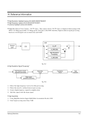
...uses normal Lens and OLPF. Reference Information Ů High-Resolution DayNight Camera (SCC-B2391/B2391P/B2091P) Ů High-Resolution Camera (SCC-B1391/B1391P/B1091P) Ů Economy DayNight Camera (SCC-B2300) Ů High Resolution Color Camera : 540 TV Lines. General OLPF CCD DSP H_LPF H_APECOM High Resolution... 14. This camera shows 540 TV Line's of high resolution image with the main signal. Ů High Sensitivity 1) Using High Resolution Super-HAD(Hole Accumulate Diode) CCD. 2) Gain-Up processing more than 30dB. Amplication Circuit High resolution Samsung Electronics 14-1...
...uses normal Lens and OLPF. Reference Information Ů High-Resolution DayNight Camera (SCC-B2391/B2391P/B2091P) Ů High-Resolution Camera (SCC-B1391/B1391P/B1091P) Ů Economy DayNight Camera (SCC-B2300) Ů High Resolution Color Camera : 540 TV Lines. General OLPF CCD DSP H_LPF H_APECOM High Resolution... 14. This camera shows 540 TV Line's of high resolution image with the main signal. Ů High Sensitivity 1) Using High Resolution Super-HAD(Hole Accumulate Diode) CCD. 2) Gain-Up processing more than 30dB. Amplication Circuit High resolution Samsung Electronics 14-1...


