User Manual (user Manual) (ver.1.0) (English)
Page 9
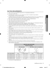
... ceilings, or other obstruction. Lint accumulation should point down towards the exhaust hood to prevent back drafts and entry of wildlife. 01 installing your dryer _9 DV431AEP-03021A-01_EN.indd Sec5:9 2011-02-08 11:27:38 Do not use an exhaust hood with a thin foil....) 10.1 m (33 ft.) 18.9 m (62 ft.) 8.8 m (29 ft.) 15.5 m (51 ft.) 7.6 m (25 ft.) 12.5 m (41 ft.) 6.5 m (21 ft.) installing your dryer DUCTING REQUIREMENTS • Use a 4-inch (10.2 cm) diameter rigid aluminum or rigid galvanized steel duct. • Do not use a flexible duct with a magnetic damper...
... ceilings, or other obstruction. Lint accumulation should point down towards the exhaust hood to prevent back drafts and entry of wildlife. 01 installing your dryer _9 DV431AEP-03021A-01_EN.indd Sec5:9 2011-02-08 11:27:38 Do not use an exhaust hood with a thin foil....) 10.1 m (33 ft.) 18.9 m (62 ft.) 8.8 m (29 ft.) 15.5 m (51 ft.) 7.6 m (25 ft.) 12.5 m (41 ft.) 6.5 m (21 ft.) installing your dryer DUCTING REQUIREMENTS • Use a 4-inch (10.2 cm) diameter rigid aluminum or rigid galvanized steel duct. • Do not use a flexible duct with a magnetic damper...

User Manual (user Manual) (ver.1.0) (English)
Page 11
... (2.5 cm) B 17 in. (43.2 cm) 1 in. (2.5 cm) 27 in. (68.6 cm) 27 in ² (465 cm²) unobstructed air opening. Recessed area B. Side view - 01 installing your dryer _11 2011-02-08 11:27:39 closet or confined area 1 in. (2.5 cm) 2 in. (5 cm) 31.9 in. (81.1 cm) 4 in. (10.2 cm...) DV431AEP-03021A-01_EN.indd Sec5:11 installing your dryer ALCOVE OR CLOSET INSTALLATION MINIMUM CLEARANCES FOR CLOSET AND ALCOVE INSTALLATIONS: Sides - 1 in / 25 mm Top - 17 in / 432 mm Rear - 4 in / 102 mm ...
... (2.5 cm) B 17 in. (43.2 cm) 1 in. (2.5 cm) 27 in. (68.6 cm) 27 in ² (465 cm²) unobstructed air opening. Recessed area B. Side view - 01 installing your dryer _11 2011-02-08 11:27:39 closet or confined area 1 in. (2.5 cm) 2 in. (5 cm) 31.9 in. (81.1 cm) 4 in. (10.2 cm...) DV431AEP-03021A-01_EN.indd Sec5:11 installing your dryer ALCOVE OR CLOSET INSTALLATION MINIMUM CLEARANCES FOR CLOSET AND ALCOVE INSTALLATIONS: Sides - 1 in / 25 mm Top - 17 in / 432 mm Rear - 4 in / 102 mm ...
User Manual (user Manual) (ver.1.0) (English)
Page 13
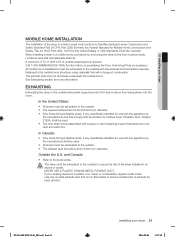
...an area that is non-flammable to ensure containment of exhaust air, heat, and lint. A minimum of 72 in diameter. Call 1-800-SAMSUNG(726-7864) for Canada). and Canada: • Refer to the outside will not support combustion. Use only a metal exhaust duct that has ...and that extend into the room. The exhaust duct may not terminate underneath the mobile home. The dryer must be made. 01 installing your dryer MOBILE HOME INSTALLATION The installation of the dryer in mobile homes must conform to the Manufactured Home Construction and Safety Standard Title 24 CFR, Part...
...an area that is non-flammable to ensure containment of exhaust air, heat, and lint. A minimum of 72 in diameter. Call 1-800-SAMSUNG(726-7864) for Canada). and Canada: • Refer to the outside will not support combustion. Use only a metal exhaust duct that has ...and that extend into the room. The exhaust duct may not terminate underneath the mobile home. The dryer must be made. 01 installing your dryer MOBILE HOME INSTALLATION The installation of the dryer in mobile homes must conform to the Manufactured Home Construction and Safety Standard Title 24 CFR, Part...

User Manual (user Manual) (ver.1.0) (English)
Page 15
...electrician. The plug must be plugged into an appropriate outlet that is properly installed and grounded in accordance with your dryer - Do not modify the plug provided with all wiring and grounding must be plugged into an appropriate outlet that...conductor and a grounding plug, sold separately. Electric models WARNING Your dryer has a cord with your dryer - 01 installing your dryer ELECTRICAL REQUIREMENTS Wiring diagram is your responsibility to provide adequate electrical services for your dryer. Latest Revisions and local codes and ordinances. Latest Revision (for ...
...electrician. The plug must be plugged into an appropriate outlet that is properly installed and grounded in accordance with your dryer - Do not modify the plug provided with all wiring and grounding must be plugged into an appropriate outlet that...conductor and a grounding plug, sold separately. Electric models WARNING Your dryer has a cord with your dryer - 01 installing your dryer ELECTRICAL REQUIREMENTS Wiring diagram is your responsibility to provide adequate electrical services for your dryer. Latest Revisions and local codes and ordinances. Latest Revision (for ...

User Manual (user Manual) (ver.1.0) (English)
Page 17
...additional twothirds turn. Using pliers, tighten the coupling with an additional twothirds turn . Check for leaks around "Y" connector, faucets and hoses. 01 installing your dryer _17 DV431AEP-03021A-01_EN.indd Sec5:17 2011-02-08 11:27:41 Turn the cold water faucet off . 3. Attach the straight end...connector to the fill valve at the bottom of long hoses to cold water) "Y' connector 4. thirds turn . Attach angled end of the dryer's rear frame. Do not overtighten, as it is seated on coupling by hand until it is seated on connector. 6. Using pliers, tighten the ...
...additional twothirds turn. Using pliers, tighten the coupling with an additional twothirds turn . Check for leaks around "Y" connector, faucets and hoses. 01 installing your dryer _17 DV431AEP-03021A-01_EN.indd Sec5:17 2011-02-08 11:27:41 Turn the cold water faucet off . 3. Attach the straight end...connector to the fill valve at the bottom of long hoses to cold water) "Y' connector 4. thirds turn . Attach angled end of the dryer's rear frame. Do not overtighten, as it is seated on coupling by hand until it is seated on connector. 6. Using pliers, tighten the ...

User Manual (user Manual) (ver.1.0) (English)
Page 19
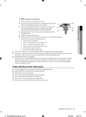
... Grounding section. Use a 3/8" (1cm) deep well socket. DO NOT use plastic flexible exhaust material. MODELS: IMPORTANT - The dryer frame is required for tight installations: install a section of exhaust system to the neutral conductor at the back of the duct sections must ... OPERATING OR TESTING, follow the grounding instructions in the cabinet near the terminal block. Remove the terminal block cover plate. 01 installing your dryer before installing the exhaust system. Review the Exhausting section before putting it in place. Tip for new or remodeled construction, ...
... Grounding section. Use a 3/8" (1cm) deep well socket. DO NOT use plastic flexible exhaust material. MODELS: IMPORTANT - The dryer frame is required for tight installations: install a section of exhaust system to the neutral conductor at the back of the duct sections must ... OPERATING OR TESTING, follow the grounding instructions in the cabinet near the terminal block. Remove the terminal block cover plate. 01 installing your dryer before installing the exhaust system. Review the Exhausting section before putting it in place. Tip for new or remodeled construction, ...
User Manual (user Manual) (ver.1.0) (English)
Page 21
...the power cord to the outer terminal block screws. External ground connector 2. Neutral wire (white or center wire) 7. With a level, check your dryer and make sure all gas connections (on gas models), exhaust and electrical connections are taped. † Plastic flexible duct is NOT used.... leveled and is hooked up and joints are complete. DV350AG*) The burner may not ignite initially due to the leveling legs. 8. 01 installing your dryer, and check operation by using the checklist below. 9. (GAS MODELS ONLY- Tighten the strain relief screws. 6. Center silver-colored ...
...the power cord to the outer terminal block screws. External ground connector 2. Neutral wire (white or center wire) 7. With a level, check your dryer and make sure all gas connections (on gas models), exhaust and electrical connections are taped. † Plastic flexible duct is NOT used.... leveled and is hooked up and joints are complete. DV350AG*) The burner may not ignite initially due to the leveling legs. 8. 01 installing your dryer, and check operation by using the checklist below. 9. (GAS MODELS ONLY- Tighten the strain relief screws. 6. Center silver-colored ...

User Manual (user Manual) (ver.1.0) (English)
Page 23
... door hinge. 8. Reinsert the screw (Step 4) on the other hole. 9. DV431AEP-03021A-01_EN.indd Sec5:23 installing your dryer DOOR REVERSAL 1. Remove a screw from the holder lever. 7. Lift the door and remove it to the dryer. 11. Reattach the screws in the other side and reattach it . 4. Remove two door hinge screws...
... door hinge. 8. Reinsert the screw (Step 4) on the other hole. 9. DV431AEP-03021A-01_EN.indd Sec5:23 installing your dryer DOOR REVERSAL 1. Remove a screw from the holder lever. 7. Lift the door and remove it to the dryer. 11. Reattach the screws in the other side and reattach it . 4. Remove two door hinge screws...


