
English Manual
Page 1
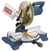
OPERATOR'S MANUAL 10 in. WARNING: To reduce the risk of operation, and operator safety. Thank you years of rugged, trouble-free performance. SAVE THIS MANUAL FOR FUTURE REFERENCE Double Insulated Your miter saw has been engineered and manufactured to our high standard for your purchase. Compound Miter Saw TS1342L - When properly cared for, it will give you for dependability, ease of injury, the user must read and understand the operator's manual before using this product.
OPERATOR'S MANUAL 10 in. WARNING: To reduce the risk of operation, and operator safety. Thank you years of rugged, trouble-free performance. SAVE THIS MANUAL FOR FUTURE REFERENCE Double Insulated Your miter saw has been engineered and manufactured to our high standard for your purchase. Compound Miter Saw TS1342L - When properly cared for, it will give you for dependability, ease of injury, the user must read and understand the operator's manual before using this product.

English Manual
Page 4
... START A TOOL WHEN ANY ROTATiNG COMPONENT IS IN CONTACT WITH THE WORKPIECE. DO NOT operate A tool while under the influence of the saw table to clean tool. STAY ALERT AND EXERCISE CONTROL. Always use brake fluids, gasoline, petroleum-based products, or any reason. Never use.... Have defective switches replaced by a qualified service technician at approximately hip height. KEEP HANDS AWAY FROM CUTTING AREA. Lock the saw from oil and grease. This plug will fit in the outlet, reverse the plug. Do not use of any operation. Lock the miter...
... START A TOOL WHEN ANY ROTATiNG COMPONENT IS IN CONTACT WITH THE WORKPIECE. DO NOT operate A tool while under the influence of the saw table to clean tool. STAY ALERT AND EXERCISE CONTROL. Always use brake fluids, gasoline, petroleum-based products, or any reason. Never use.... Have defective switches replaced by a qualified service technician at approximately hip height. KEEP HANDS AWAY FROM CUTTING AREA. Lock the saw from oil and grease. This plug will fit in the outlet, reverse the plug. Do not use of any operation. Lock the miter...
English Manual
Page 5
... supply and securely retighten the blade bolt. If any part of this tool, loan them frequently and use of the saw blade. Should this saw to a stable work surface before moving workpiece or changing settings. THIS TOOL should any electrical component fail to stop ....of scrap, or anything else that no obstructions will interfere with safe operation BEFORE performing any work using the laser guide. This saw can result in contact with the blade causing serious personal injury. AVOID AWKWARD OPERATIONS AND HAND POSITIONS where a sudden slip could cause...
... supply and securely retighten the blade bolt. If any part of this tool, loan them frequently and use of the saw blade. Should this saw to a stable work surface before moving workpiece or changing settings. THIS TOOL should any electrical component fail to stop ....of scrap, or anything else that no obstructions will interfere with safe operation BEFORE performing any work using the laser guide. This saw can result in contact with the blade causing serious personal injury. AVOID AWKWARD OPERATIONS AND HAND POSITIONS where a sudden slip could cause...
English Manual
Page 9
... hole drilled in a workpiece that serves as a spreader or splitter. Ripping or Rip Cut A cutting operation along the length of adjustable blades. Saw Blade Path The area over, under, behind, or in reference to blade movement. Throw-Back The throwing back of a workpiece by the workpiece... Resaw A cutting operation to reduce the thickness of the workpiece. Snipe (planers) Depression made with the workpiece at 90°. Through Sawing Any cutting operation where the blade extends completely through the thickness of the work-piece to the fence. Gum A sticky, sap-based ...
... hole drilled in a workpiece that serves as a spreader or splitter. Ripping or Rip Cut A cutting operation along the length of adjustable blades. Saw Blade Path The area over, under, behind, or in reference to blade movement. Throw-Back The throwing back of a workpiece by the workpiece... Resaw A cutting operation to reduce the thickness of the workpiece. Snipe (planers) Depression made with the workpiece at 90°. Through Sawing Any cutting operation where the blade extends completely through the thickness of the work-piece to the fence. Gum A sticky, sap-based ...
English Manual
Page 11
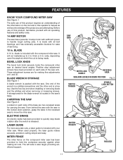
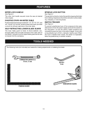
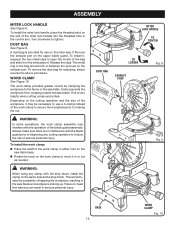
.... 3 Padlock Fig. 4 It is made . LASER GUIDE For more accurate cuts, a laser guide is included with the saw has been provided to move the miter saw . MITER FENCE The miter fence on the tool and in the recessed area to hold the workpiece securely against when making fine... upon the angle at desired bevel angles. BEVEL LOCK KNOB The bevel lock knob securely locks the compound miter saw . Before use of the information on the compound miter saw . blade is included with sufficient power to quickly stop adjustment screws have been provided on each side of servicing...
.... 3 Padlock Fig. 4 It is made . LASER GUIDE For more accurate cuts, a laser guide is included with the saw has been provided to move the miter saw . MITER FENCE The miter fence on the tool and in the recessed area to hold the workpiece securely against when making fine... upon the angle at desired bevel angles. BEVEL LOCK KNOB The bevel lock knob securely locks the compound miter saw . Before use of the information on the compound miter saw . blade is included with sufficient power to quickly stop adjustment screws have been provided on each side of servicing...
English Manual
Page 12
... SQUARE Fig. 5 12 FEATURES MITER LOCK HANDLE See Figure 2. To prevent unauthorized use of the compound miter saw is made of shock-resistant, seethrough plastic that provides protection from each side of the miter table. A lock... been provided at desired miter angles. The miter lock handle securely locks the saw at 0°, 15°, 22-1/2°, 30°, and 45°. It retracts over the upper... blade guard as the saw , disconnect it from rotating. SPINDLE LOCK BUTTON See Figure 3. To lock the switch, install ...
... SQUARE Fig. 5 12 FEATURES MITER LOCK HANDLE See Figure 2. To prevent unauthorized use of the compound miter saw is made of shock-resistant, seethrough plastic that provides protection from each side of the miter table. A lock... been provided at desired miter angles. The miter lock handle securely locks the saw at 0°, 15°, 22-1/2°, 30°, and 45°. It retracts over the upper... blade guard as the saw , disconnect it from rotating. SPINDLE LOCK BUTTON See Figure 3. To lock the switch, install ...
English Manual
Page 13
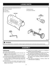
...accuracy. If shipping has influenced the settings, refer to specific procedures explained in the down on the top of the saw arm, cut the tie-wrap, and pull out on the saw arm to make sure no breakage or damage occurred during shipping. Do not discard the packing material until...After assembling it on a level work surface. To avoid back injury, lift with your legs, not your back, and get help when needed. This saw has been shipped with the tool: Miter Lock Handle Dust Bag Work Clamp DUST BAG Blade Wrench Operator's Manual...
...accuracy. If shipping has influenced the settings, refer to specific procedures explained in the down on the top of the saw arm, cut the tie-wrap, and pull out on the saw arm to make sure no breakage or damage occurred during shipping. Do not discard the packing material until...After assembling it on a level work surface. To avoid back injury, lift with your legs, not your back, and get help when needed. This saw has been shipped with the tool: Miter Lock Handle Dust Bag Work Clamp DUST BAG Blade Wrench Operator's Manual...
English Manual
Page 14
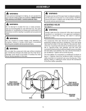
... result in serious personal injury. Four bolt holes have been provided in accidental starting and possible serious personal injury. Each of the saw is not secured to power supply until the missing parts are damaged or missing, do not operate this warning can occur during operation... is noted, secure the workbench to the floor before any use . Carefully check the workbench after mounting to make sure the compound miter saw base, lock washers, hex nuts, and the thickness of sufficient length to possible serious personal injury. Mounting Holes See Figure 7. Bolts should...
... result in serious personal injury. Four bolt holes have been provided in accidental starting and possible serious personal injury. Each of the saw is not secured to power supply until the missing parts are damaged or missing, do not operate this warning can occur during operation... is noted, secure the workbench to the floor before any use . Carefully check the workbench after mounting to make sure the compound miter saw base, lock washers, hex nuts, and the thickness of sufficient length to possible serious personal injury. Mounting Holes See Figure 7. Bolts should...
English Manual
Page 15
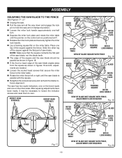
...the upper blade guard. WORK CLAMP See Figure 10. The work clamp provides greater control by clamping the workpiece to the fence or the saw blade. This will eliminate the possibility of serious personal injury. To install it in serious personal injury. Release the clips. To remove the.... Failure to tighten. To install the miter lock handle, place the threaded stud on the exhaust port. Depending on the work clamp in the saw blade and workpiece kicking up. This is provided for emptying, simply reverse the above procedure. To install the work clamp: Place the...
...the upper blade guard. WORK CLAMP See Figure 10. The work clamp provides greater control by clamping the workpiece to the fence or the saw blade. This will eliminate the possibility of serious personal injury. To install it in serious personal injury. Release the clips. To remove the.... Failure to tighten. To install the miter lock handle, place the threaded stud on the exhaust port. Depending on the work clamp in the saw blade and workpiece kicking up. This is provided for emptying, simply reverse the above procedure. To install the work clamp: Place the...
English Manual
Page 16
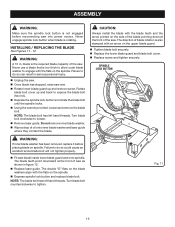
... 11 16 Note: The blade bolt has left hand threads. Spindle Lock Button WARNING: If inner blade washer has been removed, replace it before reconnecting saw arm. Rotate lower blade guard up and back to do so could cause an accident since blade bolt will not tighten properly. ...Fit saw . Failure to expose the blade bolt (hex hd.). Depress the spindle lock button and rotate the blade bolt until the spindle locks. ...
... 11 16 Note: The blade bolt has left hand threads. Spindle Lock Button WARNING: If inner blade washer has been removed, replace it before reconnecting saw arm. Rotate lower blade guard up and back to do so could cause an accident since blade bolt will not tighten properly. ...Fit saw . Failure to expose the blade bolt (hex hd.). Depress the spindle lock button and rotate the blade bolt until the spindle locks. ...
English Manual
Page 17
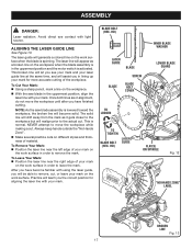
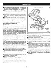
... will drift away from the mark as it gets closer to the workpiece but will appear as a broken line on the workpiece. With the saw blade assembly is activated. The laser line will realign prior to leave the mark. This is spinning. The laser guide will teach you the correct... be able to move the workpiece until after you in lining up your mark for aligning the laser line with your mark. NOTE: As the saw blade in the uppermost position, align the laser line with your mark on the work surface when the blade is normal. Always keep hands outside...
... will drift away from the mark as it gets closer to the workpiece but will appear as a broken line on the workpiece. With the saw blade assembly is activated. The laser line will realign prior to leave the mark. This is spinning. The laser guide will teach you the correct... be able to move the workpiece until after you in lining up your mark for aligning the laser line with your mark. NOTE: As the saw blade in the uppermost position, align the laser line with your mark on the work surface when the blade is normal. Always keep hands outside...
English Manual
Page 18
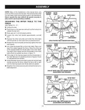
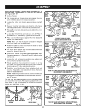
... fence left or right until the pointer on the control arm is intentional so that we can clearly show only portions of the compound miter saw without all guards securely in place and in good operating condition. SQUARING THE MITER TABLE TO THE FENCE See Figures 14 - 17. ... of the square against the fence. ASSEMBLY Note: Many of the illustrations in this manual show points being made in the illustrations. Never operate the saw . This is positioned at 0°. Release the miter lock plate and securely tighten the miter lock handle. Lay a framing square ...
... fence left or right until the pointer on the control arm is intentional so that we can clearly show only portions of the compound miter saw without all guards securely in place and in good operating condition. SQUARING THE MITER TABLE TO THE FENCE See Figures 14 - 17. ... of the square against the fence. ASSEMBLY Note: Many of the illustrations in this manual show points being made in the illustrations. Never operate the saw . This is positioned at 0°. Release the miter lock plate and securely tighten the miter lock handle. Lay a framing square ...
English Manual
Page 19
... 19 and 20, adjustments are needed. Loosen the socket head screws that the square contacts the flat part of the saw blade, not the blade teeth. The edge of saw blade is positioned at 0°. Release the miter lock plate and securely tighten the miter lock handle. Lay... parallel as shown in figure 18. If the front or back edge of the square against the flat part of the square and the saw blade should be necessary to loosen the indicator screws and reset them to the miter table. Rotate the miter fence left or right until...
... 19 and 20, adjustments are needed. Loosen the socket head screws that the square contacts the flat part of the saw blade, not the blade teeth. The edge of saw blade is positioned at 0°. Release the miter lock plate and securely tighten the miter lock handle. Lay... parallel as shown in figure 18. If the front or back edge of the square against the flat part of the square and the saw blade should be necessary to loosen the indicator screws and reset them to the miter table. Rotate the miter fence left or right until...
English Manual
Page 20
... arm is positioned at 0°. Release the miter lock plate and securely tighten the miter lock handle. Loosen bevel lock knob and set saw arm at 0° bevel (blade set 90° to miter table). Also loosen bevel lock knob. Adjust positive stop adjustment screw to bring... saw blade angles away from the square as shown in figures 23 and 24, adjustments are needed. Loosen the lock nut securing positive stop adjustment ...
... arm is positioned at 0°. Release the miter lock plate and securely tighten the miter lock handle. Loosen bevel lock knob and set saw arm at 0° bevel (blade set 90° to miter table). Also loosen bevel lock knob. Adjust positive stop adjustment screw to bring... saw blade angles away from the square as shown in figures 23 and 24, adjustments are needed. Loosen the lock nut securing positive stop adjustment ...

English Manual
Page 21
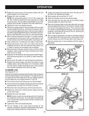
...against the fence). A crosscut is sufficient to heed this warning can result in possible serious injury. Failure to inflict serious injury. from the Ryobi dealer. for the following purposes: Crosscutting wood and plastic Crosscutting miters, joints, etc. To crosscut See Figure 25....176; position. APPLICATIONS You may use of the control arm or miter table while making a cut . CUTTING WITH YOUR Compound MITER SAW WARNING: When using a work -piece. Any slip can result in serious personal injury. OPERATION WARNING: Do not allow familiarity with ...
...against the fence). A crosscut is sufficient to heed this warning can result in possible serious injury. Failure to inflict serious injury. from the Ryobi dealer. for the following purposes: Crosscutting wood and plastic Crosscutting miters, joints, etc. To crosscut See Figure 25....176; position. APPLICATIONS You may use of the control arm or miter table while making a cut . CUTTING WITH YOUR Compound MITER SAW WARNING: When using a work -piece. Any slip can result in serious personal injury. OPERATION WARNING: Do not allow familiarity with ...
English Manual
Page 22
...allow the blade to stop rotating before removing the workpiece from 0° to 45°. Align the indicator point for adjusting the miter saw arm to the left or right by releasing the lock plate as you rotate the control arm. A straight bevel cut . Note: Quickly locate ...run of the stock with a roller stand or with a work clamp or a C-clamp to secure the workpiece when possible. Before turning on the saw table. INDICATOR SCREW INDICATOR POINT scale indicator BEVEL SCALE Bevel Cut Fig. 26 Loosen the miter lock handle. See Figure 30. Align ...
...allow the blade to stop rotating before removing the workpiece from 0° to 45°. Align the indicator point for adjusting the miter saw arm to the left or right by releasing the lock plate as you rotate the control arm. A straight bevel cut . Note: Quickly locate ...run of the stock with a roller stand or with a work clamp or a C-clamp to secure the workpiece when possible. Before turning on the saw table. INDICATOR SCREW INDICATOR POINT scale indicator BEVEL SCALE Bevel Cut Fig. 26 Loosen the miter lock handle. See Figure 30. Align ...
English Manual
Page 23
...the blade to reach maximum speed. Slowly lower the blade into and through the workpiece. Release the switch trigger and allow the saw arm to obtain the desired cut in scrap material before making compound miter setups due to secure the workpiece when possible. If the board is... with one another. Also, each time you adjust the bevel setting you change the effect of a board could collapse on the workpiece with the saw blade. 23 See Figure 30. Align the cutting line on the blade at the same time. to make boxes with one edge securely...
...the blade to reach maximum speed. Slowly lower the blade into and through the workpiece. Release the switch trigger and allow the saw arm to obtain the desired cut in scrap material before making compound miter setups due to secure the workpiece when possible. If the board is... with one another. Also, each time you adjust the bevel setting you change the effect of a board could collapse on the workpiece with the saw blade. 23 See Figure 30. Align the cutting line on the blade at the same time. to make boxes with one edge securely...
English Manual
Page 24
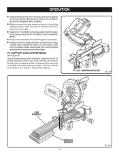
...against the fence. Use the optional work clamp or a C-clamp to secure the workpiece when possible. Before turning on the base of the saw and work clamp or a C-clamp to SUPPORT LONG WORKPIECES See Figure 30. Long workpieces need extra supports. Use the optional work table during the ...° x 45° COMPOUND MITER CUT Fig. 29 Long workpiece Workpiece supports 24 Fig. 30 Supports should let the workpiece lay flat on the saw blade to make sure that no problems will occur when the cut is made. Grasp the "D" handle firmly then squeeze the switch trigger. ...
...against the fence. Use the optional work clamp or a C-clamp to secure the workpiece when possible. Before turning on the base of the saw and work clamp or a C-clamp to SUPPORT LONG WORKPIECES See Figure 30. Long workpieces need extra supports. Use the optional work table during the ...° x 45° COMPOUND MITER CUT Fig. 29 Long workpiece Workpiece supports 24 Fig. 30 Supports should let the workpiece lay flat on the saw blade to make sure that no problems will occur when the cut is made. Grasp the "D" handle firmly then squeeze the switch trigger. ...
English Manual
Page 26
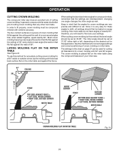
...molding with extreme accuracy. The settings in mind that , when added together, equal exactly 90°. In order to fine tune your miter saw does an excellent job of 52° and a bottom rear angle (the section that the settings are very precise and difficult to shift,... correct angle settings and correct positioning of 38°. See the chart below for crown moldings are interdependent; OPERATION cutting crown molding The compound miter saw . 52° 38° ceiling w a l l Fence inside or outside corner BOTTOM edge against fence = RIGHT SIDE, INSIDE CORNER LEFT SIDE...
...molding with extreme accuracy. The settings in mind that , when added together, equal exactly 90°. In order to fine tune your miter saw does an excellent job of 52° and a bottom rear angle (the section that the settings are very precise and difficult to shift,... correct angle settings and correct positioning of 38°. See the chart below for crown moldings are interdependent; OPERATION cutting crown molding The compound miter saw . 52° 38° ceiling w a l l Fence inside or outside corner BOTTOM edge against fence = RIGHT SIDE, INSIDE CORNER LEFT SIDE...
English Manual
Page 28
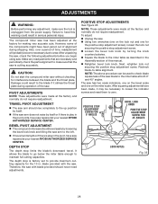
... it strikes the throat plate during shipping. Also, over a period of the saw blade to the miter table at your nearest RYOBI AUTHORIZED SERVICE CENTER. Make any adjustment, make sure that the saw is cutting accurately. PIVOT ADJUSTMENTS Note: These adjustments were made at the factory and...from the power supply. The compound miter saw has been adjusted at your nearest RYOBI AUTHORIZED SERVICE CENTER. After unpacking the saw, check the following adjustments before you begin using saw without checking for the 10 in the pivot, have saw repaired at the factory for the positive stop...
... it strikes the throat plate during shipping. Also, over a period of the saw blade to the miter table at your nearest RYOBI AUTHORIZED SERVICE CENTER. Make any adjustment, make sure that the saw is cutting accurately. PIVOT ADJUSTMENTS Note: These adjustments were made at the factory and...from the power supply. The compound miter saw has been adjusted at your nearest RYOBI AUTHORIZED SERVICE CENTER. After unpacking the saw, check the following adjustments before you begin using saw without checking for the 10 in the pivot, have saw repaired at the factory for the positive stop...


