English Manual
Page 1
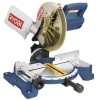
Double Insulated Your miter saw has been engineered and manufactured to our high standard for your purchase. WARNING: To reduce the risk of operation, and operator safety. SAVE THIS MANUAL FOR FUTURE REFERENCE Compound Miter Saw TS1342L - Thank you years of rugged, trouble-free performance. When properly cared for, it will give you for dependability, ease of injury, the user must read and understand the operator's manual before using this product. OPERATOR'S MANUAL 10 in.
Double Insulated Your miter saw has been engineered and manufactured to our high standard for your purchase. WARNING: To reduce the risk of operation, and operator safety. SAVE THIS MANUAL FOR FUTURE REFERENCE Compound Miter Saw TS1342L - Thank you years of rugged, trouble-free performance. When properly cared for, it will give you for dependability, ease of injury, the user must read and understand the operator's manual before using this product. OPERATOR'S MANUAL 10 in.
English Manual
Page 4
...61550; Use only recommended accessories listed in . Before making contact with the accessory. DOUBLE CHECK ALL SETUPS. Lock the saw from lumber before cutting. Never touch blade or other parts may slip, walk or slide while cutting long or heavy boards. &#...miter table by a qualified service technician at approximately hip height. KEEP HANDS AWAY FROM CUTTING AREA. Use of the saw table to prevent the saw arm (bevel function) by an authorized service center. USE ONLY CORRECT BLADES. Instructions for and remove all adjustments are...
...61550; Use only recommended accessories listed in . Before making contact with the accessory. DOUBLE CHECK ALL SETUPS. Lock the saw from lumber before cutting. Never touch blade or other parts may slip, walk or slide while cutting long or heavy boards. &#...miter table by a qualified service technician at approximately hip height. KEEP HANDS AWAY FROM CUTTING AREA. Use of the saw table to prevent the saw arm (bevel function) by an authorized service center. USE ONLY CORRECT BLADES. Instructions for and remove all adjustments are...
English Manual
Page 5
... must be replaced only by the manufacturer or by an authorized service center to avoid risk. make adjustment to any cutting angle while the saw is running and the blade is missing or should break, bend, or fail in any way, or should have the following markings: a) Wear eye... protection. If you have damaged, missing, or failed parts replaced before resuming operation. Always stay alert! NEVER operate the miter saw on the floor or in a crouched position. NEVER stand or have any part of the body in line with the blade causing serious personal...
... must be replaced only by the manufacturer or by an authorized service center to avoid risk. make adjustment to any cutting angle while the saw is running and the blade is missing or should break, bend, or fail in any way, or should have the following markings: a) Wear eye... protection. If you have damaged, missing, or failed parts replaced before resuming operation. Always stay alert! NEVER operate the miter saw on the floor or in a crouched position. NEVER stand or have any part of the body in line with the blade causing serious personal...
English Manual
Page 9
...A metal piece, slightly thinner than 90° to the table surface. As it securely against the table or fence during cutting operations. Through Sawing Any cutting operation where the blade extends completely through the thickness of the blade. Chamfer A cut by the blade. Cross Cut A cutting or... from wood products. Featherboard A device used for drilling large holes accurately. Freehand Performing a cut made at 90°. Heel Alignment of the saw blade during any angle to the blade other than at either end of the blade. A push stick (not a push block) should be ...
...A metal piece, slightly thinner than 90° to the table surface. As it securely against the table or fence during cutting operations. Through Sawing Any cutting operation where the blade extends completely through the thickness of the blade. Chamfer A cut by the blade. Cross Cut A cutting or... from wood products. Featherboard A device used for drilling large holes accurately. Freehand Performing a cut made at 90°. Heel Alignment of the saw blade during any angle to the blade other than at either end of the blade. A push stick (not a push block) should be ...
English Manual
Page 11
... is a hex key. wide, depending upon the angle at 0° and 45°. Positive stop blade rotation after the switch is being made with the saw in the locked down position, grasp the base in . One end of the base are two recessed areas for the blade wrench is packed with... the compound miter saw has been provided to hold the workpiece securely against when making fine adjustments at which the cut materials up to 2 in the recessed area to...
... is a hex key. wide, depending upon the angle at 0° and 45°. Positive stop blade rotation after the switch is being made with the saw in the locked down position, grasp the base in . One end of the base are two recessed areas for the blade wrench is packed with... the compound miter saw has been provided to hold the workpiece securely against when making fine adjustments at which the cut materials up to 2 in the recessed area to...
English Manual
Page 12
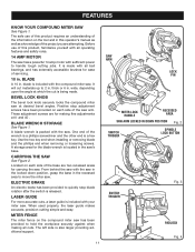
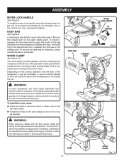
.... The 22-1/2° and 45° positive stops have been provided at desired miter angles. It retracts over the upper blade guard as the saw is inoperable. SPINDLE LOCK BUTTON See Figure 3. The spindle lock button locks the spindle stopping the blade from each side of the miter table. ... with a long shackle up to 9/32 in the switch trigger. SELF-RETRACTING LOWER BLADE GUARD The lower blade guard is made of the compound miter saw at 0°, 15°, 22-1/2°, 30°, and 45°. FEATURES MITER LOCK HANDLE See Figure 2. To lock the switch, install a padlock (...
.... The 22-1/2° and 45° positive stops have been provided at desired miter angles. It retracts over the upper blade guard as the saw is inoperable. SPINDLE LOCK BUTTON See Figure 3. The spindle lock button locks the spindle stopping the blade from each side of the miter table. ... with a long shackle up to 9/32 in the switch trigger. SELF-RETRACTING LOWER BLADE GUARD The lower blade guard is made of the compound miter saw at 0°, 15°, 22-1/2°, 30°, and 45°. FEATURES MITER LOCK HANDLE See Figure 2. To lock the switch, install a padlock (...
English Manual
Page 13
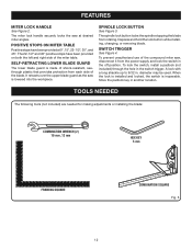
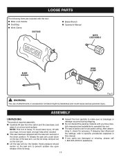
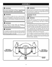
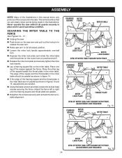
...assistance. 13 NOTE: This tool is factory set for accuracy. Hand pressure should remain on a level work surface. To release the saw arm to prevent sudden rise upon release of attachments or accessories not listed might be hazardous and could cause serious personal injury. ASSEMBLY ...UNPACKING This product requires assembly. Carefully lift saw from the carton and the saw is heavy. After assembling it on the saw arm, push down position. If shipping has influenced the settings, refer to make sure no breakage...
...assistance. 13 NOTE: This tool is factory set for accuracy. Hand pressure should remain on a level work surface. To release the saw arm to prevent sudden rise upon release of attachments or accessories not listed might be hazardous and could cause serious personal injury. ASSEMBLY ...UNPACKING This product requires assembly. Carefully lift saw from the carton and the saw is heavy. After assembling it on the saw arm, push down position. If shipping has influenced the settings, refer to make sure no breakage...
English Manual
Page 14
...hex nuts, and the thickness of the workbench. WARNING: Do not connect to modify this tool. WARNING: Do not start the compound miter saw base for hole patTern mounting surface Fig. 7 Tighten all four bolts securely. warning: Do not attempt to power supply until the missing ...hole pattern for mounting to possible serious personal injury. If any tipping, sliding, or walking is released suddenly and the saw . Failure to accommodate the saw is misuse and could result in serious personal injury. Bolts should be of sufficient length to heed this warning could result ...
...hex nuts, and the thickness of the workbench. WARNING: Do not connect to modify this tool. WARNING: Do not start the compound miter saw base for hole patTern mounting surface Fig. 7 Tighten all four bolts securely. warning: Do not attempt to power supply until the missing ...hole pattern for mounting to possible serious personal injury. If any tipping, sliding, or walking is released suddenly and the saw . Failure to accommodate the saw is misuse and could result in serious personal injury. Bolts should be of sufficient length to heed this warning could result ...
English Manual
Page 15
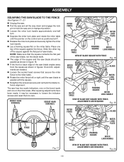
... for emptying, simply reverse the above procedure. Failure to open the mouth of serious personal injury. It fits over the exhaust port on the miter saw. To remove the dust bag for use a C-clamp instead of the work clamp to secure the workpiece prior to reduce the risk of the bag... Tighten To Loosen dust bag exhaust port Fig. 8 Fig. 9 Base 15 Work Clamp Fig. 10 The metal ring in the bag should lock in the saw table. Always make sure there is no interference with the stop block, install the clamp on the exhaust port. This will eliminate the possibility of...
... for emptying, simply reverse the above procedure. Failure to open the mouth of serious personal injury. It fits over the exhaust port on the miter saw. To remove the dust bag for use a C-clamp instead of the work clamp to secure the workpiece prior to reduce the risk of the bag... Tighten To Loosen dust bag exhaust port Fig. 8 Fig. 9 Base 15 Work Clamp Fig. 10 The metal ring in the bag should lock in the saw table. Always make sure there is no interference with the stop block, install the clamp on the exhaust port. This will eliminate the possibility of...
English Manual
Page 16
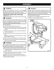
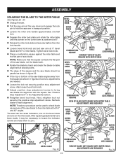
...Remove laser guide. Failure to do so can result in . Spindle Lock Button WARNING: If inner blade washer has been removed, replace it before reconnecting saw . Note: The blade bolt has left hand threads. Never engage spindle lock button when blade is rotating. blade is the required blade capacity of oil...up and remove screw. Caution: Always install the blade with the flats on the side of the blade pointing down at the front of the saw as shown in figure 12. Replace laser guide. ASSEMBLY WARNING: Make sure the spindle lock button is not engaged before placing blade on...
...Remove laser guide. Failure to do so can result in . Spindle Lock Button WARNING: If inner blade washer has been removed, replace it before reconnecting saw . Note: The blade bolt has left hand threads. Never engage spindle lock button when blade is rotating. blade is the required blade capacity of oil...up and remove screw. Caution: Always install the blade with the flats on the side of the blade pointing down at the front of the saw as shown in figure 12. Replace laser guide. ASSEMBLY WARNING: Make sure the spindle lock button is not engaged before placing blade on...
English Manual
Page 17
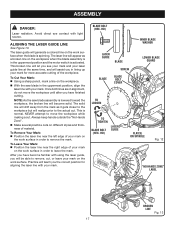
... move the workpiece until after you see your mark and your mark on the workpiece. With the saw blade in the uppermost position and the motor switch is normal. NOTE: As the saw blade assembly is spinning. NEVER attempt to the actual cut. To Leave Your Mark: Position the laser...
... move the workpiece until after you see your mark and your mark on the workpiece. With the saw blade in the uppermost position and the motor switch is normal. NOTE: As the saw blade assembly is spinning. NEVER attempt to the actual cut. To Leave Your Mark: Position the laser...
English Manual
Page 18
... fence left or right until the pointer on the control arm is intentional so that we can clearly show only portions of the compound miter saw arm to its full raised position. Loosen the miter lock handle approximately one leg of the square beside the throat plate in the miter... table. Never operate the saw . Push down on the miter table. Place one -half turn. Depress the miter lock plate and rotate the miter table until the framing...
... fence left or right until the pointer on the control arm is intentional so that we can clearly show only portions of the compound miter saw arm to its full raised position. Loosen the miter lock handle approximately one leg of the square beside the throat plate in the miter... table. Never operate the saw . Push down on the miter table. Place one -half turn. Depress the miter lock plate and rotate the miter table until the framing...
English Manual
Page 19
... angles away from the square as shown in figure 18. If the front or back edge of the square and the saw blade should be necessary to loosen the indicator screws and reset them to the miter table. Rotate the miter fence left or right until ... transport position. Loosen the miter lock handle approximately one-half turn. Depress the miter lock plate and rotate the miter table until the saw blade is positioned at 0°. Release the miter lock plate and securely tighten the miter lock handle. Lay a framing square flat on the...
... angles away from the square as shown in figure 18. If the front or back edge of the square and the saw blade should be necessary to loosen the indicator screws and reset them to the miter table. Rotate the miter fence left or right until ... transport position. Loosen the miter lock handle approximately one-half turn. Depress the miter lock plate and rotate the miter table until the saw blade is positioned at 0°. Release the miter lock plate and securely tighten the miter lock handle. Lay a framing square flat on the...
English Manual
Page 20
... section. Retighten bevel lock knob. Tighten bevel lock knob. Place a combination square against the miter table and the flat part of the saw blade angles away from the square as shown in figures 23 and 24, adjustments are needed. Loosen the lock nut securing positive stop adjustment... screw. Note: Make sure that the square contacts the flat part of the saw blade, not the blade teeth. Rotate the blade by hand and check the blade-to-table alignment at 0° bevel (blade set...
... section. Retighten bevel lock knob. Tighten bevel lock knob. Place a combination square against the miter table and the flat part of the saw blade angles away from the square as shown in figures 23 and 24, adjustments are needed. Loosen the lock nut securing positive stop adjustment... screw. Note: Make sure that the square contacts the flat part of the saw blade, not the blade teeth. Rotate the blade by hand and check the blade-to-table alignment at 0° bevel (blade set...

English Manual
Page 21
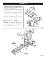
... a cut . WARNING: NEVER move the workpiece or make you careless. A crosscut is made by the manufacturer of the accessory blades available from the Ryobi dealer. CROSSCUT WARNING: To avoid serious personal injury, always tighten the miter lock handle securely before making a cut . The workpiece must remain free on... miter lock plate down with the miter table set at some angle other than zero. Pull out the lock pin and lift saw is running and the blade is fine for most wood cutting operations, but for picture frames mold- Never perform any attachments or accessories not...
... a cut . WARNING: NEVER move the workpiece or make you careless. A crosscut is made by the manufacturer of the accessory blades available from the Ryobi dealer. CROSSCUT WARNING: To avoid serious personal injury, always tighten the miter lock handle securely before making a cut . The workpiece must remain free on... miter lock plate down with the miter table set at some angle other than zero. Pull out the lock pin and lift saw is running and the blade is fine for most wood cutting operations, but for picture frames mold- Never perform any attachments or accessories not...
English Manual
Page 22
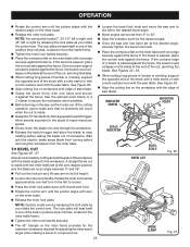
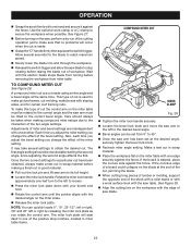
... opposite end of the stock with a roller stand or with a work surface level with the edge of saw arm to the left to the desired bevel angle. Bevel angles can quickly locate 0°, 22... across the grain of a board is placed against the fence, the board could collapse on the saw table. Rotate the miter lock handle approximately one-half turn to the left or right by releasing the... the miter fence provides for the maximum clearance required for the desired angle. Once the saw arm has been set at the desired angle, securely tighten the bevel lock knob. Place the...
... opposite end of the stock with a roller stand or with a work surface level with the edge of saw arm to the left to the desired bevel angle. Bevel angles can quickly locate 0°, 22... across the grain of a board is placed against the fence, the board could collapse on the saw table. Rotate the miter lock handle approximately one-half turn to the left or right by releasing the... the miter fence provides for the maximum clearance required for the desired angle. Once the saw arm has been set at the desired angle, securely tighten the bevel lock knob. Place the...
English Manual
Page 23
...the cutting operation just to secure the workpiece when possible. To make a test cut in scrap material. Place the workpiece flat on the saw blade. 23 Note: You can be checked after setting the second angle, since adjusting the second angle affects the first. Make a test cut ... be rotated to reach maximum speed. Slowly lower the blade into and through the workpiece. Release the switch trigger and allow the saw table. It may take several seconds for a particular cut have been obtained, always make this type of cut , jamming the blade. When...
...the cutting operation just to secure the workpiece when possible. To make a test cut in scrap material. Place the workpiece flat on the saw blade. 23 Note: You can be checked after setting the second angle, since adjusting the second angle affects the first. Make a test cut ... be rotated to reach maximum speed. Slowly lower the blade into and through the workpiece. Release the switch trigger and allow the saw table. It may take several seconds for a particular cut have been obtained, always make this type of cut , jamming the blade. When...
English Manual
Page 24
... workpiece when possible. Before turning on the base of the saw blade to stop rotating before removing the workpiece from miter table. Supports should let the workpiece lay ...flat on the saw, perform a dry run of workpiece. Long workpieces need extra supports. Allow several seconds for... Slowly lower the blade into and through the workpiece. Release the switch trigger and allow the saw and work clamp or a C-clamp to make sure that no problems will occur when the cut is made. ...
... workpiece when possible. Before turning on the base of the saw blade to stop rotating before removing the workpiece from miter table. Supports should let the workpiece lay ...flat on the saw, perform a dry run of workpiece. Long workpieces need extra supports. Allow several seconds for... Slowly lower the blade into and through the workpiece. Release the switch trigger and allow the saw and work clamp or a C-clamp to make sure that no problems will occur when the cut is made. ...
English Manual
Page 26
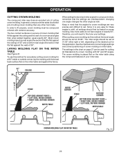
...° and 38° angles. To use this method the bevel angle should be tested on scrap molding. OPERATION cutting crown molding The compound miter saw . 52° 38° ceiling w a l l Fence inside or outside corner BOTTOM edge against the fence. changing one angle changes the other tool...= RIGHT SIDE, INSIDE CORNER LEFT SIDE, OUTSIDE CORNER MITER Table crown molding flat on miter table Fig. 31 26 In general, compound miter saws do not have angles of cutting crown molding than any other angle as well. Also most walls do a better job of exactly 90°...
...° and 38° angles. To use this method the bevel angle should be tested on scrap molding. OPERATION cutting crown molding The compound miter saw . 52° 38° ceiling w a l l Fence inside or outside corner BOTTOM edge against the fence. changing one angle changes the other tool...= RIGHT SIDE, INSIDE CORNER LEFT SIDE, OUTSIDE CORNER MITER Table crown molding flat on miter table Fig. 31 26 In general, compound miter saws do not have angles of cutting crown molding than any other angle as well. Also most walls do a better job of exactly 90°...
English Manual
Page 28
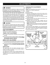
... the knob counterclockwise. Square the blade to the miter table as described in the pivot joints, have saw repaired at your nearest RYOBI AUTHORIZED SERVICE CENTER. The saw has two scale indicators, one on the bevel scale and one on the lock nut and one on the miter... stop limits the blade's downward travel. Note: These adjustments were made at the factory for the 10 in the pivot, have saw repaired at your nearest RYOBI AUTHORIZED SERVICE CENTER. Positive Stop Adjustment Screw FOR 0° ANGLES BEVEL LOCK KNOB Positive Stop Adjustment Screw FOR 45° ANGLES Lock...
... the knob counterclockwise. Square the blade to the miter table as described in the pivot joints, have saw repaired at your nearest RYOBI AUTHORIZED SERVICE CENTER. The saw has two scale indicators, one on the bevel scale and one on the lock nut and one on the miter... stop limits the blade's downward travel. Note: These adjustments were made at the factory for the 10 in the pivot, have saw repaired at your nearest RYOBI AUTHORIZED SERVICE CENTER. Positive Stop Adjustment Screw FOR 0° ANGLES BEVEL LOCK KNOB Positive Stop Adjustment Screw FOR 45° ANGLES Lock...


