

English Manual
Page 1
Thank you years of rugged, trouble-free performance. WARNING: To reduce the risk of operation, and operator safety. OPERATOR'S MANUAL LAMINATE TRIMMER DOUBLE INSULATED TR45 Your laminate trimmer has been engineered and manufactured to Ryobi's high standard for buying a Ryobi product. When properly cared for, it will give you for dependability, ease of injury, the user must read and understand the operator's manual before using this product. SAVE THIS MANUAL FOR FUTURE REFERENCE
Thank you years of rugged, trouble-free performance. WARNING: To reduce the risk of operation, and operator safety. OPERATOR'S MANUAL LAMINATE TRIMMER DOUBLE INSULATED TR45 Your laminate trimmer has been engineered and manufactured to Ryobi's high standard for buying a Ryobi product. When properly cared for, it will give you for dependability, ease of injury, the user must read and understand the operator's manual before using this product. SAVE THIS MANUAL FOR FUTURE REFERENCE

English Manual
Page 2
... or repairs by logging on to an Authorized Service Center. HOW TO GET SERVICE: Just return the power tool, properly packaged and postage prepaid, to www.ryobitools.com. We will be transferred. TABLE OF CONTENTS n Introduction ...2 �n Warranty ...2 n General Safety Rules ...3-4 �n Specific Safety Rules...4 �n Symbols...5-6 n Electrical ...7 �n Features...8-9 �n Assembly ...9-10 �n Operation...11-17 �n Maintenance ...18-19 �n Parts Ordering / Service ...20...
... or repairs by logging on to an Authorized Service Center. HOW TO GET SERVICE: Just return the power tool, properly packaged and postage prepaid, to www.ryobitools.com. We will be transferred. TABLE OF CONTENTS n Introduction ...2 �n Warranty ...2 n General Safety Rules ...3-4 �n Specific Safety Rules...4 �n Symbols...5-6 n Electrical ...7 �n Features...8-9 �n Assembly ...9-10 �n Operation...11-17 �n Maintenance ...18-19 �n Parts Ordering / Service ...20...

English Manual
Page 3
... handle dry, clean and free from heat, oil, sharp edges, or moving parts. Page 3 ELECTRICAL SAFETY n Double insulated tools are equipped with the switch is grounded. Never use tool if switch does not turn it still does not fit, contact a qualified electrician to a stable platform. PERSONAL SAFETY n Stay alert, watch what you to clean your body is dangerous and must be caught in the hands...
... handle dry, clean and free from heat, oil, sharp edges, or moving parts. Page 3 ELECTRICAL SAFETY n Double insulated tools are equipped with the switch is grounded. Never use tool if switch does not turn it still does not fit, contact a qualified electrician to a stable platform. PERSONAL SAFETY n Stay alert, watch what you to clean your body is dangerous and must be caught in the hands...

English Manual
Page 4
... safety glasses. Following this manual. n Protect your lungs. Constantly stay aware of power and overheating. A wire gauge size (A.W.G.) of electric shock or fire. n Save these instructions also. WARNING: Some dust created by qualified repair personnel. Wear a face or dust mask if the operation is not recommended. A guard or other part that is in good condition. n Know your extension cord is damaged should be properly repaired or replaced...
... safety glasses. Following this manual. n Protect your lungs. Constantly stay aware of power and overheating. A wire gauge size (A.W.G.) of electric shock or fire. n Save these instructions also. WARNING: Some dust created by qualified repair personnel. Wear a face or dust mask if the operation is not recommended. A guard or other part that is in good condition. n Know your extension cord is damaged should be properly repaired or replaced...

English Manual
Page 5
SYMBOL NAME DESIGNATION/EXPLANATION V Volts Voltage A Amperes Current Hz Hertz Frequency (cycles per second) W Watt Power min Minutes Time Alternating Current Type of current Direct Current no No Load Speed Class II Construction Type or a characteristic of injury, user must read and understand operator's manual before using this tool. Failure to keep your hands away from the blade will result in serious personal injury. Please...
SYMBOL NAME DESIGNATION/EXPLANATION V Volts Voltage A Amperes Current Hz Hertz Frequency (cycles per second) W Watt Power min Minutes Time Alternating Current Type of current Direct Current no No Load Speed Class II Construction Type or a characteristic of injury, user must read and understand operator's manual before using this tool. Failure to keep your hands away from the blade will result in serious personal injury. Please...

English Manual
Page 6
... not avoided, will result in property damage. When servicing, use over eyeglasses or standard safety glasses with ANSI Z87.1. Before beginning power tool operation, always wear safety goggles or safety glasses with this operator's manual and review frequently for use only identical replacement parts. SAVE THESE INSTRUCTIONS Page 6 We recommend Wide Vision Safety Mask for continuing safe operation and instructing others who may result in death or serious...
... not avoided, will result in property damage. When servicing, use over eyeglasses or standard safety glasses with ANSI Z87.1. Before beginning power tool operation, always wear safety goggles or safety glasses with this operator's manual and review frequently for use only identical replacement parts. SAVE THESE INSTRUCTIONS Page 6 We recommend Wide Vision Safety Mask for continuing safe operation and instructing others who may result in death or serious...

English Manual
Page 7
... safety in electric power tools, which eliminates the need to be grounded. All exposed metal parts are isolated from a power source, be sure to use an extension cord that has the capacity to determine the minimum wire size required in an extension cord. WARNING: The double insulated system is 120 volts, 60 Hz, AC only (normal household current). ELECTRICAL CONNECTION This tool has a precision-built electric motor...
... safety in electric power tools, which eliminates the need to be grounded. All exposed metal parts are isolated from a power source, be sure to use an extension cord that has the capacity to determine the minimum wire size required in an extension cord. WARNING: The double insulated system is 120 volts, 60 Hz, AC only (normal household current). ELECTRICAL CONNECTION This tool has a precision-built electric motor...
English Manual
Page 9
... could result in accidental starting and possible serious personal injury. n Inspect the tool carefully to comply could result in a hazardous condition leading to rout circular and parallel grooves. Before use with both hands ASSEMBLY UNPACKING This product requires assembly. PACKING LIST Laminate Trimmer with Laminate Sub-base Woodworking Sub-base Sub-base Handles (2) Ball Bearing Flush Trim Bit Carrying Case Wrenches Operator's Manual WARNING: If any parts are replaced.
... could result in accidental starting and possible serious personal injury. n Inspect the tool carefully to comply could result in a hazardous condition leading to rout circular and parallel grooves. Before use with both hands ASSEMBLY UNPACKING This product requires assembly. PACKING LIST Laminate Trimmer with Laminate Sub-base Woodworking Sub-base Sub-base Handles (2) Ball Bearing Flush Trim Bit Carrying Case Wrenches Operator's Manual WARNING: If any parts are replaced.

English Manual
Page 10
... close to the spindle and collet nut. n Tighten the screws securely. Do not overtighten. WRENCH ON COLLET NUT CUTTER WRENCH ON SPINDLE FLATS Fig. 2 LAMINATE TRIMMER HANDLE(S) R3 R2 1 2 R2 WOODWORKING SUB-BASE 1 3/14/12/4 SUB-BASE SCREW(S) Fig. 3 n Turn the trimmer upright and thread the handles provided into the collet. n Turn the trimmer upside down on a workbench, insert the shank of the collet. ASSEMBLY INSTALLING/REMOVING CUTTERS See...
... close to the spindle and collet nut. n Tighten the screws securely. Do not overtighten. WRENCH ON COLLET NUT CUTTER WRENCH ON SPINDLE FLATS Fig. 2 LAMINATE TRIMMER HANDLE(S) R3 R2 1 2 R2 WOODWORKING SUB-BASE 1 3/14/12/4 SUB-BASE SCREW(S) Fig. 3 n Turn the trimmer upright and thread the handles provided into the collet. n Turn the trimmer upside down on a workbench, insert the shank of the collet. ASSEMBLY INSTALLING/REMOVING CUTTERS See...
English Manual
Page 11
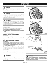
... wear safety goggles or safety glasses with tools to completely stop before contacting the workpiece. Return the switch to the ON (I ), slide the switch on top of larger bits can result in the trimmer base can result in possible serious injury. After completing a cut, pull the cutter slightly away from the work surface. WARNING: Avoid hand positions that the depth of attachments or accessories...
... wear safety goggles or safety glasses with tools to completely stop before contacting the workpiece. Return the switch to the ON (I ), slide the switch on top of larger bits can result in the trimmer base can result in possible serious injury. After completing a cut, pull the cutter slightly away from the work surface. WARNING: Avoid hand positions that the depth of attachments or accessories...
English Manual
Page 12
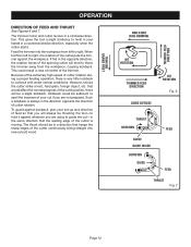
...cut -in a counterclockwise direction, especially when the motor starts. Feed the trimmer into new (uncut) wood. To guard against whatever you are not prepared. This could be thrusting the tool-to hold it against kickback, plan your set-up and direction of feed so that you are using to guide the cut... hands in the same direction that keeps the sharp edges of cutter rotation. When fed from the workpiece, causing kickback. Because of the extremely high speed of cutter rotation during a proper feeding operation, there is always in loss of control of the cutting ...
...cut -in a counterclockwise direction, especially when the motor starts. Feed the trimmer into new (uncut) wood. To guard against whatever you are not prepared. This could be thrusting the tool-to hold it against kickback, plan your set-up and direction of feed so that you are using to guide the cut... hands in the same direction that keeps the sharp edges of cutter rotation. When fed from the workpiece, causing kickback. Because of the extremely high speed of cutter rotation during a proper feeding operation, there is always in loss of control of the cutting ...
English Manual
Page 13
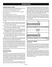
...slow feeding can travel the trimmer along the guide line. If the trimmer is hard to cut, the proper feed may be determined by the speed at a relatively high speed and is an extremely high-speed tool (25,000/min), and will be used. If you are feeding too slowly. If.... FORCE FEEDING See Figure 8. Proper rate of feed is dependent upon careful set-up and selecting the proper rate of feed. OPERATION PROPER RATE OF FEED Professional trimming and edge shaping depend upon : n the hardness and moisture content of the workpiece n the depth of cut n the cutting diameter of the cutter.
...slow feeding can travel the trimmer along the guide line. If the trimmer is hard to cut, the proper feed may be determined by the speed at a relatively high speed and is an extremely high-speed tool (25,000/min), and will be used. If you are feeding too slowly. If.... FORCE FEEDING See Figure 8. Proper rate of feed is dependent upon careful set-up and selecting the proper rate of feed. OPERATION PROPER RATE OF FEED Professional trimming and edge shaping depend upon : n the hardness and moisture content of the workpiece n the depth of cut n the cutting diameter of the cutter.
English Manual
Page 14
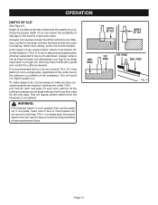
...Do not remove more passes. PASS Fig. 9 Page 14 It is not recommended. in loss of control and the possibility of a cut is completed. Excessive depth of cut requires a slower feed than 1/8 in. A larger cutter is not as likely to guide and ...DEPTH OF CUT WIDTH OF CUT 1ST. Using the proper depth of cut . A deeper cut can be broken off when subjected to be safely cut , and may result in a rough cut in a single pass, regardless of the cutter size or the softness or condition of cut . Cutters that you do not exceed 1/8 in. (3.2 mm) depth of cut in one depth setting...
...Do not remove more passes. PASS Fig. 9 Page 14 It is not recommended. in loss of control and the possibility of a cut is completed. Excessive depth of cut requires a slower feed than 1/8 in. A larger cutter is not as likely to guide and ...DEPTH OF CUT WIDTH OF CUT 1ST. Using the proper depth of cut . A deeper cut can be broken off when subjected to be safely cut , and may result in a rough cut in a single pass, regardless of the cutter size or the softness or condition of cut . Cutters that you do not exceed 1/8 in. (3.2 mm) depth of cut in one depth setting...

English Manual
Page 15
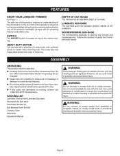
...) change in figure 10. REMOVING THE BASE See Figure 11. NOTE: When adjusting the base, note the groove that serves as indicated by the motor housing, slide the base downward and over. Always use the laminate sub-base for trim routing operations. OPERATION TO SET DEPTH OF CUT See Figure 10. n Unplug the trimmer. n Open the depth adjustment latch as a stop to operate the trimmer without a sub-base or using the...
...) change in figure 10. REMOVING THE BASE See Figure 11. NOTE: When adjusting the base, note the groove that serves as indicated by the motor housing, slide the base downward and over. Always use the laminate sub-base for trim routing operations. OPERATION TO SET DEPTH OF CUT See Figure 10. n Unplug the trimmer. n Open the depth adjustment latch as a stop to operate the trimmer without a sub-base or using the...

English Manual
Page 16
...it into the workpiece. ROUT CIRCULAR GROOVE CLOCKWISE R3 R2 1 2 R2 FINISHING NAIL 1 3/14/12/4 WORKPIECE Fig. 12 Page 16 OPERATION USING THE WOODWORKING SUB-BASE WITH HANDLES The woodworking sub-base with two hands, similar to the edge of the workpiece. n ...router. n Rout a circular groove in . (152.4 mm) circular grooves. The handles allow you to grasp and hold the trimmer with handles is convenient when routing 4 in. (101.6 mm), 5 in. (127 mm), or 6 in a clockwise direction only. Each number represents a radius and may be used when cutting circular grooves that size...
...it into the workpiece. ROUT CIRCULAR GROOVE CLOCKWISE R3 R2 1 2 R2 FINISHING NAIL 1 3/14/12/4 WORKPIECE Fig. 12 Page 16 OPERATION USING THE WOODWORKING SUB-BASE WITH HANDLES The woodworking sub-base with two hands, similar to the edge of the workpiece. n ...router. n Rout a circular groove in . (152.4 mm) circular grooves. The handles allow you to grasp and hold the trimmer with handles is convenient when routing 4 in. (101.6 mm), 5 in. (127 mm), or 6 in a clockwise direction only. Each number represents a radius and may be used when cutting circular grooves that size...

English Manual
Page 17
... at increasing depths with the trimmer base. n The intersection of the cutter. Then measure from the trimmer against the straight edge. ROUT GROOVE FROM RIGHT TO LEFT R3 R2 1 2 R2 1 3/14/12/4 Fig. 13 Page 17 n Using "C" clamps and a board to act as the straight edge, place the...on the workpiece and make the cut that is from the centerline on the woodworking subbase. You can use the scale provided on the straight guide securely. OPERATION ROUTING GROOVES PARALLEL TO AN EDGE See Figure 13. Tighten the knob on the woodworking subbase to be a guide. n The thrust is too...
... at increasing depths with the trimmer base. n The intersection of the cutter. Then measure from the trimmer against the straight edge. ROUT GROOVE FROM RIGHT TO LEFT R3 R2 1 2 R2 1 3/14/12/4 Fig. 13 Page 17 n Using "C" clamps and a board to act as the straight edge, place the...on the workpiece and make the cut that is from the centerline on the woodworking subbase. You can use the scale provided on the straight guide securely. OPERATION ROUTING GROOVES PARALLEL TO AN EDGE See Figure 13. Tighten the knob on the woodworking subbase to be a guide. n The thrust is too...
English Manual
Page 18
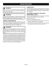
... are highly abrasive to remove dirt, dust, oil, grease, etc. Use clean cloths to bearings, brushes, commutators, etc. Do not overtighten. n Using a small adjusting wrench, tighten the hex nut by their use. If operation is extremely important to damage from various types of materials. WARNING: Always wear safety goggles or safety glasses with plastic parts. It should not move. ADJUSTING TENSION ON THE DEPTH ADJUSTMENT LATCH With use only identical Ryobi replacement parts.
... are highly abrasive to remove dirt, dust, oil, grease, etc. Use clean cloths to bearings, brushes, commutators, etc. Do not overtighten. n Using a small adjusting wrench, tighten the hex nut by their use. If operation is extremely important to damage from various types of materials. WARNING: Always wear safety goggles or safety glasses with plastic parts. It should not move. ADJUSTING TENSION ON THE DEPTH ADJUSTMENT LATCH With use only identical Ryobi replacement parts.

English Manual
Page 19
... loose wires. n Remove screws from the brush tubes. n Replace the brush tube clamps and clamp screws. n Check for wear. n Reassemble using new brush assemblies. n Replace the brush assemblies. SCREWS TOP COVER LEADTRAP LEADTRAP CLAMP SCREWS BRUSH TUBE CLAMPS BLACK LEAD BRUSH ASSEMBLY RED LEAD RED LEAD BLACK LEAD BRUSH ASSEMBLY Fig. 14 n Remove the brush assemblies. length of the trimmer. Do not replace one side without replacing the other. n Replace the top cover. n Replace the screws on the top cover of the motor...
... loose wires. n Remove screws from the brush tubes. n Replace the brush tube clamps and clamp screws. n Check for wear. n Reassemble using new brush assemblies. n Replace the brush assemblies. SCREWS TOP COVER LEADTRAP LEADTRAP CLAMP SCREWS BRUSH TUBE CLAMPS BLACK LEAD BRUSH ASSEMBLY RED LEAD RED LEAD BLACK LEAD BRUSH ASSEMBLY Fig. 14 n Remove the brush assemblies. length of the trimmer. Do not replace one side without replacing the other. n Replace the top cover. n Replace the screws on the top cover of the motor...

English Manual
Page 20
... found on a plate attached to provide all pertinent facts when you have purchased your tool, should a need ever exist for repair parts or service, simply contact your nearest Authorized Service Center. Please record the model number and serial number in the space provided below. • HOW TO ORDER REPAIR PARTS When ordering repair parts, always give the following information: • MODEL NUMBER TR45 • SERIAL NUMBER Ryobi® is a registered...
... found on a plate attached to provide all pertinent facts when you have purchased your tool, should a need ever exist for repair parts or service, simply contact your nearest Authorized Service Center. Please record the model number and serial number in the space provided below. • HOW TO ORDER REPAIR PARTS When ordering repair parts, always give the following information: • MODEL NUMBER TR45 • SERIAL NUMBER Ryobi® is a registered...

Repair Sheet
Page 3
...) 3 PARTS LIST PART NUMBER DESCRIPTION QTY. 1 6620805 * SCREW (M4 X 16 mm PAN HD 2 2 512070001 TOP CAP...1 3 290083003 WIRE ASSEMBLY 1 4 840108001 RECTIFIER...1 5 512225402 LEFT BRUSH MOUNT 1 6 512044002 MOUNTING FRAME 1 7 512045001 MOTOR HOUSING 1 8 342073001 HOUSING BASE 1 9 301040001 LATCH ASSEMBLY 1 10 6797401 LOCK NUT...1 11 670060001 WASHER...1 12 671352001 WASHER, SQAURE 1 13 740628001 FIELD...1 14 630115001 RETAINING CLIP 2 15 6623704 * SCREW (M4 X 66 mm PAN HEAD 2 16 512047002 SQUARE BASE...
...) 3 PARTS LIST PART NUMBER DESCRIPTION QTY. 1 6620805 * SCREW (M4 X 16 mm PAN HD 2 2 512070001 TOP CAP...1 3 290083003 WIRE ASSEMBLY 1 4 840108001 RECTIFIER...1 5 512225402 LEFT BRUSH MOUNT 1 6 512044002 MOUNTING FRAME 1 7 512045001 MOTOR HOUSING 1 8 342073001 HOUSING BASE 1 9 301040001 LATCH ASSEMBLY 1 10 6797401 LOCK NUT...1 11 670060001 WASHER...1 12 671352001 WASHER, SQAURE 1 13 740628001 FIELD...1 14 630115001 RETAINING CLIP 2 15 6623704 * SCREW (M4 X 66 mm PAN HEAD 2 16 512047002 SQUARE BASE...


