

Starter Guide
Page 1
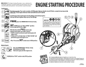
... throttle trigger. Pull the starter grip until the engine runs. Allow the engine to run for 10 seconds, then set the choke lever to the RUN position. To stop the engine: To stop position " ". Please call our Customer Service Department for starting. ADDENDUM 30cc Starting Instructions WARNING: This Addendum is not a substitute for Starting and Stopping in the Operation section of injury, user must read and understand operator's manual before using...
... throttle trigger. Pull the starter grip until the engine runs. Allow the engine to run for 10 seconds, then set the choke lever to the RUN position. To stop the engine: To stop position " ". Please call our Customer Service Department for starting. ADDENDUM 30cc Starting Instructions WARNING: This Addendum is not a substitute for Starting and Stopping in the Operation section of injury, user must read and understand operator's manual before using...
Engine Starting Procedure
Page 1
... the PRIMER BULB 10 times slowly. 4 SET CHOKE lever to RUN. Set choke lever to " FULL CHOKE " position. For any fuel spillage. Troubleshooting tips are also available in this product. SET 6 RUN After 10 seconds, choke lever to "HALF CHOKE" and 6 pull starter grip until engine runs. ENGINE STARTING PROCEDURE Cold Engine: 1 First time use E15 or E85 fuel (or fuel containing greater than 10% ethanol) in your product, call the Ryobi® Help Line! It is not a substitute for reading the operator's manual...
... the PRIMER BULB 10 times slowly. 4 SET CHOKE lever to RUN. Set choke lever to " FULL CHOKE " position. For any fuel spillage. Troubleshooting tips are also available in this product. SET 6 RUN After 10 seconds, choke lever to "HALF CHOKE" and 6 pull starter grip until engine runs. ENGINE STARTING PROCEDURE Cold Engine: 1 First time use E15 or E85 fuel (or fuel containing greater than 10% ethanol) in your product, call the Ryobi® Help Line! It is not a substitute for reading the operator's manual...
User Manual
Page 3
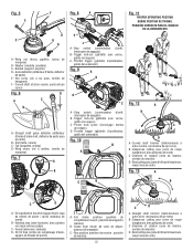
...) B - SET TO RUN C A - Primer bulb (poire d'amorçage, bomba de cebado) D - PULL UNTIL UNIT STARTS 6. Choke lever (levier de volet de départ, palanca del anegador) C - Straight shaft trimmer (taille-bordures à arbre droit, recortadora de eje recto) B - Direction of rotation (sens de rotation, sentido de rotación) D - SET TO FULL CHOKE 3. PULL UNTIL UNIT STARTS 6. PULL UNTIL UNIT ATTEMPTS TO START (MAX 4X) (DO NOT PULL THROTTLE TRIGGER) 4. SET...
...) B - SET TO RUN C A - Primer bulb (poire d'amorçage, bomba de cebado) D - PULL UNTIL UNIT STARTS 6. Choke lever (levier de volet de départ, palanca del anegador) C - Straight shaft trimmer (taille-bordures à arbre droit, recortadora de eje recto) B - Direction of rotation (sens de rotation, sentido de rotación) D - SET TO FULL CHOKE 3. PULL UNTIL UNIT STARTS 6. PULL UNTIL UNIT ATTEMPTS TO START (MAX 4X) (DO NOT PULL THROTTLE TRIGGER) 4. SET...

User Manual
Page 7
... you experience any adjustments or repairs except for early morning or late afternoon hours when temperatures are approached, stop the engine and remove the spark plug wire before starting engine. Replace any damaged parts before using this unit. Do not start or operate the engine in a confined space, building, near open windows, or in a container approved for loose fasteners, fuel leaks, etc. When operating the unit...
... you experience any adjustments or repairs except for early morning or late afternoon hours when temperatures are approached, stop the engine and remove the spark plug wire before starting engine. Replace any damaged parts before using this unit. Do not start or operate the engine in a confined space, building, near open windows, or in a container approved for loose fasteners, fuel leaks, etc. When operating the unit...

User Manual
Page 8
... set down. Never cut with a clutch, be appropriate to vibration. For such use blades, flailing devices, wire, or rope. English When the unit is properly installed and securely fastened. Keep string head below waist level. Make sure fasteners are properly and securely attached. Never use , it may be sure the cutting attachment stops turning when the engine idles. Use only the manufacturer's replacement line in any other occasional users for prolonged use...
... set down. Never cut with a clutch, be appropriate to vibration. For such use blades, flailing devices, wire, or rope. English When the unit is properly installed and securely fastened. Keep string head below waist level. Make sure fasteners are properly and securely attached. Never use , it may be sure the cutting attachment stops turning when the engine idles. Use only the manufacturer's replacement line in any other occasional users for prolonged use...

User Manual
Page 10
... installation. PACKING LIST C430 Trimmer Assembly Front Handle Curved Shaft Grass Deflector Bottle of 4-Cycle Lubricant Paper Funnel Hanger Cap Operator's Manual S430 Trimmer Assembly Front Handle Straight Shaft Grass Deflector Bottle of the information on the tool and in . FEATURES PRODUCT SPECIFICATIONS Weight - (without fuel) C430...10.7 lbs. WARNING: Do not use of this product requires an understanding of 4-Cycle Lubricant Paper Funnel Hanger Cap Operator's Manual 6 - KNOW YOUR STRING TRIMMER See Figure 1. n If any parts...
... installation. PACKING LIST C430 Trimmer Assembly Front Handle Curved Shaft Grass Deflector Bottle of 4-Cycle Lubricant Paper Funnel Hanger Cap Operator's Manual S430 Trimmer Assembly Front Handle Straight Shaft Grass Deflector Bottle of the information on the tool and in . FEATURES PRODUCT SPECIFICATIONS Weight - (without fuel) C430...10.7 lbs. WARNING: Do not use of this product requires an understanding of 4-Cycle Lubricant Paper Funnel Hanger Cap Operator's Manual 6 - KNOW YOUR STRING TRIMMER See Figure 1. n If any parts...

User Manual
Page 11
... line cut-off blade on the coupler of the power head shaft and remove the end cap from the front handle. Install the front handle onto the top side of a coupler device. Stop the engine and disconnect the spark plug wire. Loosen the knob on the grass deflector is fully tightened before operating equipment; C430 See Figure 5. Remove hex screw, washer, and wing nut from the spark plug when assembling parts...
... line cut-off blade on the coupler of the power head shaft and remove the end cap from the front handle. Install the front handle onto the top side of a coupler device. Stop the engine and disconnect the spark plug wire. Loosen the knob on the grass deflector is fully tightened before operating equipment; C430 See Figure 5. Remove hex screw, washer, and wing nut from the spark plug when assembling parts...
User Manual
Page 12
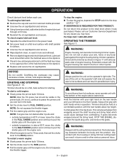
...; Remove the wing screw from a new engine after first use of this product. WARNING: Do not use of an oxygenated fuel containing more than 10% ethanol) in serious personal injury. FUELING AND REFUELING THE TRIMMER WARNING: Gasoline and its vapors are not. Avoid spillage. Prior to as E10) is shipped with Ryobi 4-cycle 20W50 engine lubricant. A spark arrestor may be emitted from the grass...
...; Remove the wing screw from a new engine after first use of this product. WARNING: Do not use of an oxygenated fuel containing more than 10% ethanol) in serious personal injury. FUELING AND REFUELING THE TRIMMER WARNING: Gasoline and its vapors are not. Avoid spillage. Prior to as E10) is shipped with Ryobi 4-cycle 20W50 engine lubricant. A spark arrestor may be emitted from the grass...
User Manual
Page 13
... the string head, STOP THE ENGINE, disconnect the spark plug wire, and remove the grass. WARNING: Engine housing can result in operation. NOTE: After the 7th press, fuel should fall within the hatched area on the front handle. To restart a warm engine: Slowly press the primer bulb 10 times. Set the choke lever to surface. Unscrew the oil cap/dipstick and remove. Wipe dipstick clean; Any contact with all body parts...
... the string head, STOP THE ENGINE, disconnect the spark plug wire, and remove the grass. WARNING: Engine housing can result in operation. NOTE: After the 7th press, fuel should fall within the hatched area on the front handle. To restart a warm engine: Slowly press the primer bulb 10 times. Set the choke lever to surface. Unscrew the oil cap/dipstick and remove. Wipe dipstick clean; Any contact with all body parts...

User Manual
Page 14
...; Run engine at the operator. The straight shaft trimmer cuts when passing the unit from left to left. do the cutting; Advance the line whenever you may wear line rapidly. Avoid trees and shrubs. To advance the cutting line manually: Stop the engine and disconnect the spark plug wire. Push the knob in illustration. Use the tip of line to do not force string head into uncut grass...
...; Run engine at the operator. The straight shaft trimmer cuts when passing the unit from left to left. do the cutting; Advance the line whenever you may wear line rapidly. Avoid trees and shrubs. To advance the cutting line manually: Stop the engine and disconnect the spark plug wire. Push the knob in illustration. Use the tip of line to do not force string head into uncut grass...
User Manual
Page 15
... engine and disconnect the spark plug wire. Rotate the spool clockwise as described in serious personal injury or property damage. long. Pull the line from the drive shaft. Insert the new spool into the string head. GENERAL MAINTENANCE Avoid using solvents when cleaning plastic parts. of the spool. Rotate the spool clockwise to Line Replacement later in objects being thrown into the eyelet on the string trimmer housing. MAINTENANCE WARNING: When servicing, use...
... engine and disconnect the spark plug wire. Rotate the spool clockwise as described in serious personal injury or property damage. long. Pull the line from the drive shaft. Insert the new spool into the string head. GENERAL MAINTENANCE Avoid using solvents when cleaning plastic parts. of the spool. Rotate the spool clockwise to Line Replacement later in objects being thrown into the eyelet on the string trimmer housing. MAINTENANCE WARNING: When servicing, use...

User Manual
Page 16
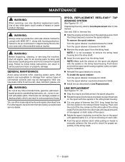
... the cutting attachment turning at idle. WARNING: Do not change the engine lubricant: Stop the engine and disconnect the spark plug wire. NOTICE: Be careful not to follow these instructions could result in serious personal injury. MAINTENANCE IDLE SPEED ADJUSTMENT See Figure 20. NOTE: If the foam filter element is still warm but not hot. FUEL CAP, TANK, AND LINES WARNING: Check for adjustment and discontinue use until the repair is hot. electrode gap. CHANGING ENGINE...
... the cutting attachment turning at idle. WARNING: Do not change the engine lubricant: Stop the engine and disconnect the spark plug wire. NOTICE: Be careful not to follow these instructions could result in serious personal injury. MAINTENANCE IDLE SPEED ADJUSTMENT See Figure 20. NOTE: If the foam filter element is still warm but not hot. FUEL CAP, TANK, AND LINES WARNING: Check for adjustment and discontinue use until the repair is hot. electrode gap. CHANGING ENGINE...
User Manual
Page 17
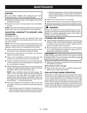
... specification before proceeding. Remove the screw from the rocker arm cover. HIGH ALTITUDE ENGINE OPERATION Please have an authorized service center restore high altitude modified engines to children. Remove engine cover and set aside. Position camshaft by all engine parts are qualified to an authorized service center. Stop the engine and disconnect the spark plug wire. Remove the cover and set aside. Using a Torx screwdriver, remove the screw from the top engine cover. WARNING: Ensure all engine cover...
... specification before proceeding. Remove the screw from the rocker arm cover. HIGH ALTITUDE ENGINE OPERATION Please have an authorized service center restore high altitude modified engines to children. Remove engine cover and set aside. Position camshaft by all engine parts are qualified to an authorized service center. Stop the engine and disconnect the spark plug wire. Remove the cover and set aside. Using a Torx screwdriver, remove the screw from the top engine cover. WARNING: Ensure all engine cover...

User Manual
Page 18
... your product, call the Ryobi® Help Line! CALL US FIRST For any questions about operating or maintaining your complete satisfaction. 14 - MAINTENANCE MAINTENANCE SCHEDULE Maintenance Part Inspect For Damage Before Each Use Clean Every 5 Hours Replace Every 25 Hours or Yearly Replace Every 50 Hours * AIR FILTER ASSY includes: Filter X * CARBURETOR ASSY * FUEL TANK ASSY includes: Fuel Lines X Fuel Cap X Fuel Filter...X * IGNITION ASSY includes: Spark Plug...X * NOTICE: THE USE OF EMISSION CONTROL COMPONENTS OTHER THAN THOSE...
... your product, call the Ryobi® Help Line! CALL US FIRST For any questions about operating or maintaining your complete satisfaction. 14 - MAINTENANCE MAINTENANCE SCHEDULE Maintenance Part Inspect For Damage Before Each Use Clean Every 5 Hours Replace Every 25 Hours or Yearly Replace Every 50 Hours * AIR FILTER ASSY includes: Filter X * CARBURETOR ASSY * FUEL TANK ASSY includes: Fuel Lines X Fuel Cap X Fuel Filter...X * IGNITION ASSY includes: Spark Plug...X * NOTICE: THE USE OF EMISSION CONTROL COMPONENTS OTHER THAN THOSE...

User Manual
Page 19
... Push primer bulb until the engine starts and runs. Contact a servicing dealer. speed. Pull lines while alternately pressing down position. No fuel. NOTE: Depending on and releasing spool retainer. Spark plug fouled. Refer to starting. Check engine lubricant and add if necessary prior to Cleaning the Air Filter earlier in this manual. SOLUTION Clean or replace spark plug. Set the choke lever to increase idle erates but will not idle needs adjustment. speed and emits excessive smoke Spark arrestor screen is worn too short. Clean air filter. Idle speed screw on...
... Push primer bulb until the engine starts and runs. Contact a servicing dealer. speed. Pull lines while alternately pressing down position. No fuel. NOTE: Depending on and releasing spool retainer. Spark plug fouled. Refer to starting. Check engine lubricant and add if necessary prior to Cleaning the Air Filter earlier in this manual. SOLUTION Clean or replace spark plug. Set the choke lever to increase idle erates but will not idle needs adjustment. speed and emits excessive smoke Spark arrestor screen is worn too short. Clean air filter. Idle speed screw on...

User Manual
Page 20
housing and string head Operating trimmer at full throttle. 16 - damaged. Cut tall grass from the top down to turn POSSIBLE CAUSE SOLUTION Screw threads are dirty or Clean threads and lubricate with grease - English Operate trimmer at part throttle. PROBLEM Spool retainer hard to prevent wrapping. TROUBLESHOOTING IF THESE SOLUTIONS DO NOT SOLVE THE PROBLEM CONTACT YOUR AUTHORIZED SERVICE DEALER. provement, replace the spool retainer. if no im- Grass wraps around driveshaft Cutting tall grass at ground level.
housing and string head Operating trimmer at full throttle. 16 - damaged. Cut tall grass from the top down to turn POSSIBLE CAUSE SOLUTION Screw threads are dirty or Clean threads and lubricate with grease - English Operate trimmer at part throttle. PROBLEM Spool retainer hard to prevent wrapping. TROUBLESHOOTING IF THESE SOLUTIONS DO NOT SOLVE THE PROBLEM CONTACT YOUR AUTHORIZED SERVICE DEALER. provement, replace the spool retainer. if no im- Grass wraps around driveshaft Cutting tall grass at ground level.

User Manual
Page 21
... by an authorized service center for warranty work must be cause for any product previously manufactured. Tune-ups - Bump Knobs, Outer Spools, Cutting Lines, Inner Reels, Starter Pulleys, Starter Ropes, Drive Belts, Tines, Felt Washers, Hitch Pins, Mulching Blades, Blower Fans, Blower and Vacuum Tubes, Vacuum Bag and Straps, Guide Bars, Saw Chains, Blades Techtronic Industries North America, Inc., reserves the right to change or improve the design of any RYOBI® brand...
... by an authorized service center for warranty work must be cause for any product previously manufactured. Tune-ups - Bump Knobs, Outer Spools, Cutting Lines, Inner Reels, Starter Pulleys, Starter Ropes, Drive Belts, Tines, Felt Washers, Hitch Pins, Mulching Blades, Blower Fans, Blower and Vacuum Tubes, Vacuum Bag and Straps, Guide Bars, Saw Chains, Blades Techtronic Industries North America, Inc., reserves the right to change or improve the design of any RYOBI® brand...

User Manual 2
Page 3
... Air Filter Cover 1 940734067 Starting Label 1 22 940971028 Oil Hang Tag 1 23 518548001 Bottom Cover 1 24 T660619001 Screw (#6-19 x 1/2 in ., T25 Torx Pan Hd. Key Nos. 36-39 1 Not Shown: 990000203 Operator's Manual 8-26-13 (Rev:02) * Standard Hardware Item - NUMBER DESCRIPTION QTY 660563002 Screw (M4 x 20 mm, T20 Torx Pan Hd 4 120950026 Control Handle Assembly 1 760700002 Switch (Momentary Contact 1 638431001 Strap Hanger 1 518695002 Trigger Lock 1 678818001 Spring...
... Air Filter Cover 1 940734067 Starting Label 1 22 940971028 Oil Hang Tag 1 23 518548001 Bottom Cover 1 24 T660619001 Screw (#6-19 x 1/2 in ., T25 Torx Pan Hd. Key Nos. 36-39 1 Not Shown: 990000203 Operator's Manual 8-26-13 (Rev:02) * Standard Hardware Item - NUMBER DESCRIPTION QTY 660563002 Screw (M4 x 20 mm, T20 Torx Pan Hd 4 120950026 Control Handle Assembly 1 760700002 Switch (Momentary Contact 1 638431001 Strap Hanger 1 518695002 Trigger Lock 1 678818001 Spring...

User Manual 2
Page 5
... 518924003 Oil Pan 1 42 570709002 Oil Pan Gasket 1 43 300759005 Fuel Filter 1 44 310816006 Fuel Cap 1 45 310585012 Fuel Tank w/Cap (Inc. Key Nos. 43-44 1 46 660970002 Shoulder Screw (M4 x 14 mm, T25 Torx Truss Hd 2 47 526450001 Throttle Cable Guide 1 48 660970008 Shoulder Screw (M4 x 19 mm, T25 Torx Truss Hd 1 5 Hd.).......1 678343001 Lock Washer (ID5.1 x OD9 x 1.3t 3 309324001 Muffler Assembly 1 901702002 Muffler Gasket 1 660780002 Screw (M4...
... 518924003 Oil Pan 1 42 570709002 Oil Pan Gasket 1 43 300759005 Fuel Filter 1 44 310816006 Fuel Cap 1 45 310585012 Fuel Tank w/Cap (Inc. Key Nos. 43-44 1 46 660970002 Shoulder Screw (M4 x 14 mm, T25 Torx Truss Hd 2 47 526450001 Throttle Cable Guide 1 48 660970008 Shoulder Screw (M4 x 19 mm, T25 Torx Truss Hd 1 5 Hd.).......1 678343001 Lock Washer (ID5.1 x OD9 x 1.3t 3 309324001 Muffler Assembly 1 901702002 Muffler Gasket 1 660780002 Screw (M4...

User Manual 2
Page 6
...Easy String Cutting Head Assembly (Inc. Key Nos. 8-12 1 KEY PART NO. NUMBER DESCRIPTION QTY 1 940726013 Expand-it Label 1 Warning Decal 1 Straight Shaft Assembly 1 Screw (10-24 x 5/8 in 1 Clamp 1 Spacer 1 Screw (1/4-20 x 1-1/4 in., Hex Hd 1 Gear Head 1 Flanged Washer 1 Stringhead Adapter w/Shaft 1 Spool Retainer (Red 1 Hanger Cap 1 Wing Screw (1/4-20 x 1-1/4 in 1 Grass Deflector Assembly 1 Main Housing 1 Compression Spring 1 Cutting Line 1 Cover-Spool 1 Spool 1 Reel Easy String Cutting Head Assembly (Inc. 15-19).....1 6 Ryobi 30cc String Trimmers Model Numbers...
...Easy String Cutting Head Assembly (Inc. Key Nos. 8-12 1 KEY PART NO. NUMBER DESCRIPTION QTY 1 940726013 Expand-it Label 1 Warning Decal 1 Straight Shaft Assembly 1 Screw (10-24 x 5/8 in 1 Clamp 1 Spacer 1 Screw (1/4-20 x 1-1/4 in., Hex Hd 1 Gear Head 1 Flanged Washer 1 Stringhead Adapter w/Shaft 1 Spool Retainer (Red 1 Hanger Cap 1 Wing Screw (1/4-20 x 1-1/4 in 1 Grass Deflector Assembly 1 Main Housing 1 Compression Spring 1 Cutting Line 1 Cover-Spool 1 Spool 1 Reel Easy String Cutting Head Assembly (Inc. 15-19).....1 6 Ryobi 30cc String Trimmers Model Numbers...


