Operation Manual
Page 3
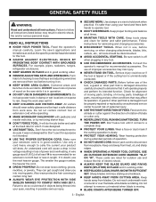
... use , before turning it was not designed for lubricating and changing accessories. DISCONNECT TOOLS. Check for alignment of moving parts, binding of moving parts, breakage of electric shock. ALWAYS KEEP THE BLADE GUARD AND RIVING KNIFE (SPLITTER) IN PLACE and in electric shock,... sure switch is damaged must be carefully checked to avoid risk of power and overheating. Before further use and reduce the risk of parts, mounting and any tool. USE RECOMMENDED ACCESSORIES. These cords are removed from receptacle. Sharp blades minimize stalling and kickback. ...
... use , before turning it was not designed for lubricating and changing accessories. DISCONNECT TOOLS. Check for alignment of moving parts, binding of moving parts, breakage of electric shock. ALWAYS KEEP THE BLADE GUARD AND RIVING KNIFE (SPLITTER) IN PLACE and in electric shock,... sure switch is damaged must be carefully checked to avoid risk of power and overheating. Before further use and reduce the risk of parts, mounting and any tool. USE RECOMMENDED ACCESSORIES. These cords are removed from receptacle. Sharp blades minimize stalling and kickback. ...
Operation Manual
Page 4
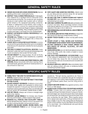
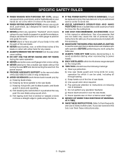
...not making contact with or without yellow stripes is equipped with incorrect size holes. When ripping narrow stock, always use only identical replacement parts. If tool is the equipment-grounding conductor. Watch what you are included with the accessory. DOUBLE CHECK ALL SETUPS. ...in ripping or cross cutting. Use a featherboard and push blocks for safe use brake fluids, gasoline, petroleum-based products, or any other moving parts during use. NEVER START A TOOL WHEN ANY ROTATING COMPONENT IS IN CONTACT WITH THE WORKPIECE. DO NOT OPERATE A ...
...not making contact with or without yellow stripes is equipped with incorrect size holes. When ripping narrow stock, always use only identical replacement parts. If tool is the equipment-grounding conductor. Watch what you are included with the accessory. DOUBLE CHECK ALL SETUPS. ...in ripping or cross cutting. Use a featherboard and push blocks for safe use brake fluids, gasoline, petroleum-based products, or any other moving parts during use. NEVER START A TOOL WHEN ANY ROTATING COMPONENT IS IN CONTACT WITH THE WORKPIECE. DO NOT OPERATE A ...
Operation Manual
Page 5
... markings: a) Wear eye protection. c) Keeping riving knife, anti-kickback pawls, and blade guard in this tool, loan them frequently and use either hand for any part of your body in line with either the rip fence or miter gauge to position and guide the work that are included with the accessory...
... markings: a) Wear eye protection. c) Keeping riving knife, anti-kickback pawls, and blade guard in this tool, loan them frequently and use either hand for any part of your body in line with either the rip fence or miter gauge to position and guide the work that are included with the accessory...
Operation Manual
Page 8
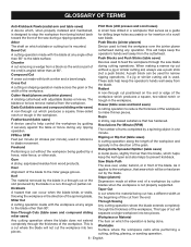
... done. Through Sawing Any cutting operation where the blade extends completely through the thickness of the cut removing a wedge from a block so the end (or part of the workpiece. Worktable Surface where the workpiece rests while performing a cutting, drilling, planing, or sanding operation. 8 - English Cross Cut A cutting or shaping operation made...
... done. Through Sawing Any cutting operation where the blade extends completely through the thickness of the cut removing a wedge from a block so the end (or part of the workpiece. Worktable Surface where the workpiece rests while performing a cutting, drilling, planing, or sanding operation. 8 - English Cross Cut A cutting or shaping operation made...
Operation Manual
Page 13
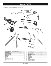
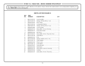
LOOSE PARTS The following items are included with anti-kickback pawls 1 B. Handle Assembly 1 D. Hex Key (5 mm 1 L. Lock Nut (M5 4 N. Stand Leg 4 Q. Open End Wrench 1 13 - Blade Guard with your table saw: I . Screw 1 H. Lock Screw (M5 4 M. English Handle End Cap 1 E. Sliding Table Assembly 1 J. Closed End Wrench 1 T. Indicator 1 G. Rip indicator end cap 1 I J H K FG A R ON B E C D L P P M Q S T A. Wheel 2 S. Lock Nut 2 P. Flat Washer (8 mm 4 O. Crosspiece 1 R. Rip Fence 1 F. Miter Gauge 1 C. Screw 1 Fig. 5 K.
LOOSE PARTS The following items are included with anti-kickback pawls 1 B. Handle Assembly 1 D. Hex Key (5 mm 1 L. Lock Nut (M5 4 N. Stand Leg 4 Q. Open End Wrench 1 13 - Blade Guard with your table saw: I . Screw 1 H. Lock Screw (M5 4 M. English Handle End Cap 1 E. Sliding Table Assembly 1 J. Closed End Wrench 1 T. Indicator 1 G. Rip indicator end cap 1 I J H K FG A R ON B E C D L P P M Q S T A. Wheel 2 S. Lock Nut 2 P. Flat Washer (8 mm 4 O. Crosspiece 1 R. Rip Fence 1 F. Miter Gauge 1 C. Screw 1 Fig. 5 K.

Operation Manual
Page 14
... not operate this leg stand with your legs, not your product when you have been improperly assembled could result in back injury. Locate the following parts: Stand leg 4 Hex nut (5 mm 4 Hex bolt (5 mm 4 Lock nut (8 mm 2 Crosspiece 1 NOTE: During shipping, the foam block between ..., refer to specific procedures explained in . Ignoring these precautions can occur during shipping. Do not discard the packing material until the parts are replaced. After assembling it . WARNING: Do not lift the saw without help when needed. NOTE: This tool is factory set for ...
... not operate this leg stand with your legs, not your product when you have been improperly assembled could result in back injury. Locate the following parts: Stand leg 4 Hex nut (5 mm 4 Hex bolt (5 mm 4 Lock nut (8 mm 2 Crosspiece 1 NOTE: During shipping, the foam block between ..., refer to specific procedures explained in . Ignoring these precautions can occur during shipping. Do not discard the packing material until the parts are replaced. After assembling it . WARNING: Do not lift the saw without help when needed. NOTE: This tool is factory set for ...

Operation Manual
Page 15
... up. Cut the zip tie that holds the support brackets together. Fold out the stand. Insert the with the holes in the lower part of the four 5 mm hex bolts through all legs with a lock nut. LEG PIVOT NUT PLATE INNER STAND SUPPORT BRACKET LATCH INNER STAND SUPPORT BRACKET...
... up. Cut the zip tie that holds the support brackets together. Fold out the stand. Insert the with the holes in the lower part of the four 5 mm hex bolts through all legs with a lock nut. LEG PIVOT NUT PLATE INNER STAND SUPPORT BRACKET LATCH INNER STAND SUPPORT BRACKET...

Operation Manual
Page 21
BLADE GUARD WARNING: Replace the blade guard if the anti-kickback pawls are part of the way. Unplug the saw. Raise the saw . They should only be used for different blade widths. If the blade guard is ...
BLADE GUARD WARNING: Replace the blade guard if the anti-kickback pawls are part of the way. Unplug the saw. Raise the saw . They should only be used for different blade widths. If the blade guard is ...

Operation Manual
Page 42
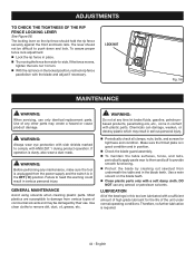
... indicator to be parallel. The edge of the saw blade should not require setting during assembly. NOTE: Make sure that the square contacts the flat part of the square and the saw blade, not the blade teeth. Lock the bevel locking lever. Tighten the adjustment screw. Check ...continue to adjust if needed. If needed . The adjustment screws must be parallel. English NOTE: Make sure that the square contacts the flat part of the saw have been set at the factory and, unless damaged in shipping, should be below the saw blade, not the blade teeth. ...
... indicator to be parallel. The edge of the saw blade should not require setting during assembly. NOTE: Make sure that the square contacts the flat part of the square and the saw blade, not the blade teeth. Lock the bevel locking lever. Tighten the adjustment screw. Check ...continue to adjust if needed. If needed . The adjustment screws must be parallel. English NOTE: Make sure that the square contacts the flat part of the saw have been set at the factory and, unless damaged in shipping, should be below the saw blade, not the blade teeth. ...
Operation Manual
Page 44
...Always wear eye protection with side shields marked to provide smooth functioning. Protect the blade by their use only identical replacement parts. Use a resin solvent on the rip fence should not be damaged by cleaning out sawdust from various types of commercial solvents and... may create a hazard or cause product damage. GENERAL MAINTENANCE Avoid using solvents when cleaning plastic parts. Therefore, no further lubrication is in the locked position, recheck rip fence parallelism with ANSI Z87.1 during product operation. English ...
...Always wear eye protection with side shields marked to provide smooth functioning. Protect the blade by their use only identical replacement parts. Use a resin solvent on the rip fence should not be damaged by cleaning out sawdust from various types of commercial solvents and... may create a hazard or cause product damage. GENERAL MAINTENANCE Avoid using solvents when cleaning plastic parts. Therefore, no further lubrication is in the locked position, recheck rip fence parallelism with ANSI Z87.1 during product operation. English ...

Parts Diagram
Page 3
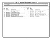
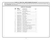
...PART NO. NUMBER DESCRIPTION QTY 1 089240015704 Throat Plate Assembly (Inc. Key Nos. 5 and 43 1 43 089240016903 Stand Instruction Label 1 44 089240016085 Rear Support 1 45 089037011019 Rear Rod 2 46 089110101146 Screw w/Washer (1/4-20 x 1/2 in . Key Nos. 2 and 6-8 1 2 089240015100 Screw (M4 x 70 mm, Button Soc. MODEL NUMBER RTS22... Nut (M6 4 41 089037011027 Screw (M6 x 25 mm 4 42 089240016040 Extension Table Assembly (Inc. RYOBI 10 in. Soc. Hd 2 18 089110101024 Screw w/Washer (M6 x 12 mm, Hex. Soc. Hd...
...PART NO. NUMBER DESCRIPTION QTY 1 089240015704 Throat Plate Assembly (Inc. Key Nos. 5 and 43 1 43 089240016903 Stand Instruction Label 1 44 089240016085 Rear Support 1 45 089037011019 Rear Rod 2 46 089110101146 Screw w/Washer (1/4-20 x 1/2 in . Key Nos. 2 and 6-8 1 2 089240015100 Screw (M4 x 70 mm, Button Soc. MODEL NUMBER RTS22... Nut (M6 4 41 089037011027 Screw (M6 x 25 mm 4 42 089240016040 Extension Table Assembly (Inc. RYOBI 10 in. Soc. Hd 2 18 089110101024 Screw w/Washer (M6 x 12 mm, Hex. Soc. Hd...
Parts Diagram
Page 5
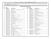
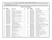
...RTS22/RTS22T The model number will be found on a label attached to the cabinet. Hd 1 16 089037007034 Hex Nut (3/8-16 2 17 089037007033 Block 1 18 089037011047 Washer (OD13 x ID6.5 x 0.5t 1 19 089037007029 C-Ring 1 20 080015001458 Spring Pin (D8 x 90 mm 1 44 089240015207 Blade (10 in . NUMBER DESCRIPTION QTY KEY PART...089037007018 Screw (M6 x 15 mm, Hex Soc. RYOBI 10 in. NUMBER DESCRIPTION QTY 1 089240015112 Screw (M6 x 8 mm, Special Hex. PARTS LIST FOR FIGURE B KEY PART NO. Hd 2 50 089037007023 Riving Knife Base 1...
...RTS22/RTS22T The model number will be found on a label attached to the cabinet. Hd 1 16 089037007034 Hex Nut (3/8-16 2 17 089037007033 Block 1 18 089037011047 Washer (OD13 x ID6.5 x 0.5t 1 19 089037007029 C-Ring 1 20 080015001458 Spring Pin (D8 x 90 mm 1 44 089240015207 Blade (10 in . NUMBER DESCRIPTION QTY KEY PART...089037007018 Screw (M6 x 15 mm, Hex Soc. RYOBI 10 in. NUMBER DESCRIPTION QTY 1 089240015112 Screw (M6 x 8 mm, Special Hex. PARTS LIST FOR FIGURE B KEY PART NO. Hd 2 50 089037007023 Riving Knife Base 1...
Parts Diagram
Page 6
...correspondence regarding your 10 in ., Hex Flange Hd.)..........1 67 089240015089 Lock Nut (M4 1 6 NUMBER DESCRIPTION QTY KEY PART NO. TABLE SAW or when ordering parts. Key Nos. 56-61 1 56 089037007912 Outer Guard Warning Label 1 57 089037007908 Warning Label (Upper Barrier 1 ...E 1 66 080015001446 Screw (1/4-20 x 3/4 in . NUMBER DESCRIPTION QTY 55 089240015144 Blade Guard Assembly w/AKP (Inc. TABLE SAW - PARTS LIST FOR FIGURE B KEY PART NO. MODEL NUMBER RTS22/RTS22T The model number will be found on a label attached to the cabinet...
...correspondence regarding your 10 in ., Hex Flange Hd.)..........1 67 089240015089 Lock Nut (M4 1 6 NUMBER DESCRIPTION QTY KEY PART NO. TABLE SAW or when ordering parts. Key Nos. 56-61 1 56 089037007912 Outer Guard Warning Label 1 57 089037007908 Warning Label (Upper Barrier 1 ...E 1 66 080015001446 Screw (1/4-20 x 3/4 in . NUMBER DESCRIPTION QTY 55 089240015144 Blade Guard Assembly w/AKP (Inc. TABLE SAW - PARTS LIST FOR FIGURE B KEY PART NO. MODEL NUMBER RTS22/RTS22T The model number will be found on a label attached to the cabinet...
Parts Diagram
Page 8
...PART NO. Key No. 50, RTS22)..... 1 Dust Chute Assy. (Inc. Key No. 50, RTS22T)... 1 Dust Chute Door 1 Screw (M4 x 10 mm, Truss Hd 1 Data Label (RTS22 1 Data Label (RTS22T 1 Screw (M4 x 5 mm, Truss Hd 1 Lock Nut (M4 1 Screw (M4 x 10 mm, Truss Hd 2 Screw (M6 x 30 mm, Truss Soc. RYOBI...M4 x 12 mm, Round Hd 3 Reinforcement Plate 1 Front Panel Assembly (Inc. TABLE SAW - MODEL NUMBER RTS22/RTS22T The model number will be found on a label attached to the cabinet. NUMBER DESCRIPTION QTY KEY PART NO. Cap Hd 1 Clamp Plate Assembly 1 Wire Lock 1 Lock Nut (M6 1 8 Key No. 44...
...PART NO. Key No. 50, RTS22)..... 1 Dust Chute Assy. (Inc. Key No. 50, RTS22T)... 1 Dust Chute Door 1 Screw (M4 x 10 mm, Truss Hd 1 Data Label (RTS22 1 Data Label (RTS22T 1 Screw (M4 x 5 mm, Truss Hd 1 Lock Nut (M4 1 Screw (M4 x 10 mm, Truss Hd 2 Screw (M6 x 30 mm, Truss Soc. RYOBI...M4 x 12 mm, Round Hd 3 Reinforcement Plate 1 Front Panel Assembly (Inc. TABLE SAW - MODEL NUMBER RTS22/RTS22T The model number will be found on a label attached to the cabinet. NUMBER DESCRIPTION QTY KEY PART NO. Cap Hd 1 Clamp Plate Assembly 1 Wire Lock 1 Lock Nut (M6 1 8 Key No. 44...
Parts Diagram
Page 10
... SAW - Always mention the model number in all correspondence regarding your 10 in . PARTS LIST FOR FIGURE D KEY PART NO. Hd 2 11 089110101120 Fence Block 1 12 089240015159 Rod 1 13 089110101108 Washer ... x 8.5 mm, Flat Hd 2 20 089240015168 Indicator 1 21 089240015197 Screw (M4 x 10 mm, Truss Hd 1 10 MODEL NUMBER RTS22/RTS22T The model number will be found on a label attached to the cabinet. NUMBER DESCRIPTION QTY 1 089110101101 Lock Nut (M6 1 2... Holder 1 9 089240015162 Rip Fence 1 10 089110101107 Screw (M6 x 15 mm, Truss Soc. RYOBI 10 in .
... SAW - Always mention the model number in all correspondence regarding your 10 in . PARTS LIST FOR FIGURE D KEY PART NO. Hd 2 11 089110101120 Fence Block 1 12 089240015159 Rod 1 13 089110101108 Washer ... x 8.5 mm, Flat Hd 2 20 089240015168 Indicator 1 21 089240015197 Screw (M4 x 10 mm, Truss Hd 1 10 MODEL NUMBER RTS22/RTS22T The model number will be found on a label attached to the cabinet. NUMBER DESCRIPTION QTY 1 089110101101 Lock Nut (M6 1 2... Holder 1 9 089240015162 Rip Fence 1 10 089110101107 Screw (M6 x 15 mm, Truss Soc. RYOBI 10 in .
Parts Diagram
Page 11
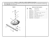
RYOBI 10 in . MODEL NUMBER RTS22/RTS22T The model number will be found on a label attached to the cabinet. TABLE SAW or when ordering parts. Hd 1 4 089037007078 Screw (M4 X 14.8 MM 1 5 089040002706 Miter Gauge 1 6 080015001475 Nylon Washer (OD16 x ID6.5 x 2t ...2 11 Always mention the model number in all correspondence regarding your 10 in . TABLE SAW - FIGURE E 9 8 7 6 5 PARTS LIST FOR FIGURE E KEY PART NO. NUMBER DESCRIPTION QTY 1 089240015177 Miter Gauge Rod 1 2 080015001563 Pointer 1 3 080015001662 Screw (3/16-24 x 1/4 in., Round.
RYOBI 10 in . MODEL NUMBER RTS22/RTS22T The model number will be found on a label attached to the cabinet. TABLE SAW or when ordering parts. Hd 1 4 089037007078 Screw (M4 X 14.8 MM 1 5 089040002706 Miter Gauge 1 6 080015001475 Nylon Washer (OD16 x ID6.5 x 2t ...2 11 Always mention the model number in all correspondence regarding your 10 in . TABLE SAW - FIGURE E 9 8 7 6 5 PARTS LIST FOR FIGURE E KEY PART NO. NUMBER DESCRIPTION QTY 1 089240015177 Miter Gauge Rod 1 2 080015001563 Pointer 1 3 080015001662 Screw (3/16-24 x 1/4 in., Round.
Parts Diagram
Page 12
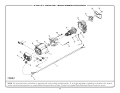
TABLE SAW - RYOBI 10 in. To avoid the possibility of the double insulated system. Contact your nearest Ryobi Authorized Service Center. MODEL NUMBER RTS22/RTS22T 20 21 19 18 7 8 11 3 14 13 12 10 9 87 6 1 1 2 4 15 17 17 16 14 FIGURE F 5 NOTE: The assembly shown represents an important part of alteration or damage to the system, service should be performed by your nearest Ryobi Authorized Service Center for service. 12
TABLE SAW - RYOBI 10 in. To avoid the possibility of the double insulated system. Contact your nearest Ryobi Authorized Service Center. MODEL NUMBER RTS22/RTS22T 20 21 19 18 7 8 11 3 14 13 12 10 9 87 6 1 1 2 4 15 17 17 16 14 FIGURE F 5 NOTE: The assembly shown represents an important part of alteration or damage to the system, service should be performed by your nearest Ryobi Authorized Service Center for service. 12
Parts Diagram
Page 13
... Assembly 1 20 089240015139 Gear Box Cover 1 21 089110101012 Lock Nut (M5 1 13 PARTS LIST FOR FIGURE F KEY PART NO. TABLE SAW or when ordering parts. Hd 2 2 089110101081 Wire Clamp 1 3 089037011050 Screw w/Washer (M5 x 35 mm, Round. RYOBI 10 in. MODEL NUMBER RTS22/RTS22T The model number will be found on a label attached to the cabinet.
... Assembly 1 20 089240015139 Gear Box Cover 1 21 089110101012 Lock Nut (M5 1 13 PARTS LIST FOR FIGURE F KEY PART NO. TABLE SAW or when ordering parts. Hd 2 2 089110101081 Wire Clamp 1 3 089037011050 Screw w/Washer (M5 x 35 mm, Round. RYOBI 10 in. MODEL NUMBER RTS22/RTS22T The model number will be found on a label attached to the cabinet.
Parts Diagram
Page 14
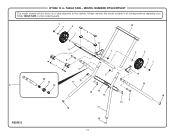
MODEL NUMBER RTS22/RTS22T The model number will be found on a label attached to the cabinet. TABLE SAW or when ordering parts. 1 2 3 10 4 2 5 12 11 1 2 3 6 8 7 9 2 1 1 13 20 15 21 17 9 22 19 16 14 15 18 8 16 18 17 FIGURE G 18 14 TABLE SAW - Always mention the model number in all correspondence regarding your 10 in . RYOBI 10 in .
MODEL NUMBER RTS22/RTS22T The model number will be found on a label attached to the cabinet. TABLE SAW or when ordering parts. 1 2 3 10 4 2 5 12 11 1 2 3 6 8 7 9 2 1 1 13 20 15 21 17 9 22 19 16 14 15 18 8 16 18 17 FIGURE G 18 14 TABLE SAW - Always mention the model number in all correspondence regarding your 10 in . RYOBI 10 in .

Parts Diagram
Page 15
... 1 Not Shown: 089240016702 Complete Stand Assembly (Inc. TABLE SAW or when ordering parts. RYOBI 10 in . PARTS LIST FOR FIGURE G KEY PART NO. NUMBER DESCRIPTION QTY 1 000999130010 Lock Nut (M8 4 2 089240016095 Washer (OD16 x ID8 x 2t 4 3 089240016096 6 in . TABLE SAW - MODEL NUMBER RTS22/RTS22T The model number will be found on a label attached to the cabinet...
... 1 Not Shown: 089240016702 Complete Stand Assembly (Inc. TABLE SAW or when ordering parts. RYOBI 10 in . PARTS LIST FOR FIGURE G KEY PART NO. NUMBER DESCRIPTION QTY 1 000999130010 Lock Nut (M8 4 2 089240016095 Washer (OD16 x ID8 x 2t 4 3 089240016096 6 in . TABLE SAW - MODEL NUMBER RTS22/RTS22T The model number will be found on a label attached to the cabinet...


