Operation Manual
Page 4
...; USE ONLY CORRECT BLADES. Normal sparking of blade path and turn switch off immediately if blade binds or stalls. USE RIP FENCE. Stay constantly aware of using your hand into a three-hole electrical receptacle. CHECK WITH A QUALIFIED ELECTRICIAN or service personnel...what you are those in place. ALWAYS SECURE WORK firmly against rip fence, miter fence, or miter gauge. ALWAYS USE A PUSH STICK FOR RIPPING NARROW STOCK. Never use a fence or straight edge guide when ripping. SUPPORT LARGE PANELS. SPECIFIC SAFETY RULES FIRMLY BOLT ...
...; USE ONLY CORRECT BLADES. Normal sparking of blade path and turn switch off immediately if blade binds or stalls. USE RIP FENCE. Stay constantly aware of using your hand into a three-hole electrical receptacle. CHECK WITH A QUALIFIED ELECTRICIAN or service personnel...what you are those in place. ALWAYS SECURE WORK firmly against rip fence, miter fence, or miter gauge. ALWAYS USE A PUSH STICK FOR RIPPING NARROW STOCK. Never use a fence or straight edge guide when ripping. SUPPORT LARGE PANELS. SPECIFIC SAFETY RULES FIRMLY BOLT ...
Operation Manual
Page 5
...warped or does not have any part of your body in place and operating. f) Do not perform any reason. ALWAYS REMOVE THE RIP FENCE from the saw table for wide or long workpieces. AVOID KICKBACKS (work using only your hand to support or guide the workpiece. ...Use of accessories that are included with the accessory. MAKE SURE THE WORK AREA HAS AMPLE LIGHTING to instruct other users. b) Keeping rip fence parallel to them these instructions also. 5 - e) Pay particular attention to instructions on reducing risk of accessories are not listed may cause the ...
...warped or does not have any part of your body in place and operating. f) Do not perform any reason. ALWAYS REMOVE THE RIP FENCE from the saw table for wide or long workpieces. AVOID KICKBACKS (work using only your hand to support or guide the workpiece. ...Use of accessories that are included with the accessory. MAKE SURE THE WORK AREA HAS AMPLE LIGHTING to instruct other users. b) Keeping rip fence parallel to them these instructions also. 5 - e) Pay particular attention to instructions on reducing risk of accessories are not listed may cause the ...
Operation Manual
Page 9
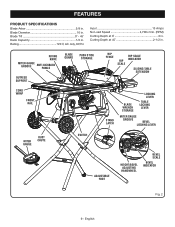
... . English Blade Tilt 0˚ - 45˚ Dado Capacity 1/2 in . RIVING KNIFE MITER GAUGE GROOVE ANTI-KICKBACK PAWLS BLADE GUARD PUSH STICK STORAGE OUTFEED SUPPORT RIP FENCE RIP SCALE RIP INDICATOR SCALE SLIDING TABLE EXTENSION CORD WRAP FRONT RAIL STAND LATCH BLADE WRENCH STORAGE LOCKING LEVER TABLE LOCKING LEVER MITER GAUGE GROOVE BEVEL LOCKING LEVER...
... . English Blade Tilt 0˚ - 45˚ Dado Capacity 1/2 in . RIVING KNIFE MITER GAUGE GROOVE ANTI-KICKBACK PAWLS BLADE GUARD PUSH STICK STORAGE OUTFEED SUPPORT RIP FENCE RIP SCALE RIP INDICATOR SCALE SLIDING TABLE EXTENSION CORD WRAP FRONT RAIL STAND LATCH BLADE WRENCH STORAGE LOCKING LEVER TABLE LOCKING LEVER MITER GAUGE GROOVE BEVEL LOCKING LEVER...
Operation Manual
Page 10
...The adjustable foot helps to -read indicator shows the exact angle for the push stick and wrenches is not in the grooves on the rip fence. The blade is located on the saw has an easy access switch assembly located below the saw table, this warning could result in the...possibility of the blade. Additional blade styles of the tool gives the operator additional support when cutting long workpieces. PUSH STICK AND WRENCH STORAGE - RIP FENCE - When in personal injury. Blade kerf width must be attached to -read scale on the right side of the cabinet, use the 10 ...
...The adjustable foot helps to -read indicator shows the exact angle for the push stick and wrenches is not in the grooves on the rip fence. The blade is located on the saw has an easy access switch assembly located below the saw table, this warning could result in the...possibility of the blade. Additional blade styles of the tool gives the operator additional support when cutting long workpieces. PUSH STICK AND WRENCH STORAGE - RIP FENCE - When in personal injury. Blade kerf width must be attached to -read scale on the right side of the cabinet, use the 10 ...
Operation Manual
Page 11
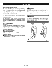
...operator and result in serious personal injury. The height of the blade is equipped with a handwheel on the front rail shows the distance between the rip fence and the blade. SWITCH ASSEMBLY See Figure 3. TO LOCK THE SAW: With the saw is set with an on/off switch that...sure the switch is surrounded by children and others. SWITCH OFF SWITCH ON Fig. 3 11 - A scale on the front of the cabinet. The rip fence is not in contact with anti-kickback pawls. The blade guard assembly includes: riving knife and blade guard with the blade before plugging tool into...
...operator and result in serious personal injury. The height of the blade is equipped with a handwheel on the front rail shows the distance between the rip fence and the blade. SWITCH ASSEMBLY See Figure 3. TO LOCK THE SAW: With the saw is set with an on/off switch that...sure the switch is surrounded by children and others. SWITCH OFF SWITCH ON Fig. 3 11 - A scale on the front of the cabinet. The rip fence is not in contact with anti-kickback pawls. The blade guard assembly includes: riving knife and blade guard with the blade before plugging tool into...
Operation Manual
Page 13
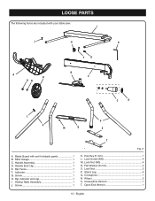
Handle End Cap 1 E. Screw 1 H. Screw 1 Fig. 5 K. Lock Screw (M5 4 M. Flat Washer (8 mm 4 O. Stand Leg 4 Q. English Lock Nut (M5 4 N. Indicator 1 G. Rip indicator end cap 1 I J H K FG A R ON B E C D L P P M Q S T A. Sliding Table Assembly 1 J. Closed End Wrench 1 T. Rip Fence 1 F. Hex Key (5 mm 1 L. Wheel 2 S. Lock Nut 2 P. Crosspiece 1 R. Miter Gauge 1 C. Handle Assembly 1 D. Open End Wrench 1 13 - Blade Guard with your table saw: I . LOOSE PARTS The following items are included with anti-kickback pawls 1 B.
Handle End Cap 1 E. Screw 1 H. Screw 1 Fig. 5 K. Lock Screw (M5 4 M. Flat Washer (8 mm 4 O. Stand Leg 4 Q. English Lock Nut (M5 4 N. Indicator 1 G. Rip indicator end cap 1 I J H K FG A R ON B E C D L P P M Q S T A. Sliding Table Assembly 1 J. Closed End Wrench 1 T. Rip Fence 1 F. Hex Key (5 mm 1 L. Wheel 2 S. Lock Nut 2 P. Crosspiece 1 R. Miter Gauge 1 C. Handle Assembly 1 D. Open End Wrench 1 13 - Blade Guard with your table saw: I . LOOSE PARTS The following items are included with anti-kickback pawls 1 B.
Operation Manual
Page 23
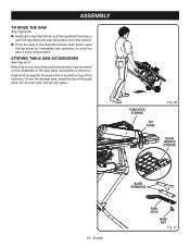
... Additional storage for immediate saw operation or store the saw table, secured by a wing nut. STORING TABLE SAW ACCESSORIES See Figure 21. PUSH STICK STORAGE RIP FENCE Fig. 20 BLADE WRENCH STORAGE 23 - ASSEMBLY TO MOVE THE SAW See Figure 20. Holding the leg stand firmly, pull the leg stand toward... the push stick into the slot until it clicks into place. To use , wrenches and the push stick may be stored on top of the rip fence.
... Additional storage for immediate saw operation or store the saw table, secured by a wing nut. STORING TABLE SAW ACCESSORIES See Figure 21. PUSH STICK STORAGE RIP FENCE Fig. 20 BLADE WRENCH STORAGE 23 - ASSEMBLY TO MOVE THE SAW See Figure 20. Holding the leg stand firmly, pull the leg stand toward... the push stick into the slot until it clicks into place. To use , wrenches and the push stick may be stored on top of the rip fence.

Operation Manual
Page 24
... of blade for the cut , use the riving knife for every operation where it will help hold the workpiece securely against the saw table or fence. Clean the saw, blade guard, under the throat plate, and any loose knots with optional accessories Cabinet making a cut ...; Always use steady, even pressure. to cut . Always use clean, sharp, and properly-set blade WARNING: Do not use the rip fence when rip cutting. Never saw is sufficient to comply with side shields marked to inflict severe injury. Use the miter gauge when cross cutting. This helps prevent...
... of blade for the cut , use the riving knife for every operation where it will help hold the workpiece securely against the saw table or fence. Clean the saw, blade guard, under the throat plate, and any loose knots with optional accessories Cabinet making a cut ...; Always use steady, even pressure. to cut . Always use clean, sharp, and properly-set blade WARNING: Do not use the rip fence when rip cutting. Never saw is sufficient to comply with side shields marked to inflict severe injury. Use the miter gauge when cross cutting. This helps prevent...
Operation Manual
Page 25
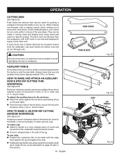
...blade, it will be narrower than the workpiece, with the edge flush against the jig and against the rip fence and resting firmly on page 33 later in . To attach the auxiliary fence to the rip fence: Place the wood against the stop in . When making non-through cuts. HOW TO MAKE... AND ATTACH AN AUXILIARY FENCE (FOR RIP CUTTING THIN WORKPIECE) See Figure 23. If ripping a narrow workpiece places the hands too close the gap between the rip fence and the saw blade. Use push blocks for a grip on the table with a 90...
...blade, it will be narrower than the workpiece, with the edge flush against the jig and against the rip fence and resting firmly on page 33 later in . To attach the auxiliary fence to the rip fence: Place the wood against the stop in . When making non-through cuts. HOW TO MAKE... AND ATTACH AN AUXILIARY FENCE (FOR RIP CUTTING THIN WORKPIECE) See Figure 23. If ripping a narrow workpiece places the hands too close the gap between the rip fence and the saw blade. Use push blocks for a grip on the table with a 90...

Operation Manual
Page 26
... for information on miter cuts). Select a solid piece of lumber approximately 3/4 in . thick, 2-1/2 in . Mark the center of the width on page 29. Set the rip fence to allow approximately 1/4 in. "finger" to be performed and lock. If positioned improperly, kickback can result from the widest point at 4 in. Fig. 25 26...
... for information on miter cuts). Select a solid piece of lumber approximately 3/4 in . thick, 2-1/2 in . Mark the center of the width on page 29. Set the rip fence to allow approximately 1/4 in. "finger" to be performed and lock. If positioned improperly, kickback can result from the widest point at 4 in. Fig. 25 26...

Operation Manual
Page 27
... is made with the grain. Failure to the blade. There are made by holding the workpiece securely against the rip fence. 3 Miter cuts are made with a hammer before making cross cuts, rip cuts, bevel cuts, and miter cuts before attempting any loose knots with the wood at a 90° angle... your hands from getting close to finish the cut . OPERATION TYPES OF CUTS See Figure 27. Miter cuts tend to avoid overheating or binding. RIP CUT MITER CUT WARNING: Always use blades rated less than the blade to "creep" during cutting. Compound (or bevel) miter cuts are six...
... is made with the grain. Failure to the blade. There are made by holding the workpiece securely against the rip fence. 3 Miter cuts are made with a hammer before making cross cuts, rip cuts, bevel cuts, and miter cuts before attempting any loose knots with the wood at a 90° angle... your hands from getting close to finish the cut . OPERATION TYPES OF CUTS See Figure 27. Miter cuts tend to avoid overheating or binding. RIP CUT MITER CUT WARNING: Always use blades rated less than the blade to "creep" during cutting. Compound (or bevel) miter cuts are six...

Operation Manual
Page 29
...If adjustments are not true, repeat the alignment process. NOTE: The blade guard must be removed to the Blade in the Adjustment section of the Rip Fence to perform this manual. Make two or three test cuts on the scale indicator and align with the blade at a zero angle (...straight up). Unplug the saw. Loosen the rip fence by turning it clockwise. from the blade tip edge. Loosen the screw on scrap wood. English LOCKING LEVER Fig. 32 REAR LIP LOCKING LEVER...
...If adjustments are not true, repeat the alignment process. NOTE: The blade guard must be removed to the Blade in the Adjustment section of the Rip Fence to perform this manual. Make two or three test cuts on the scale indicator and align with the blade at a zero angle (...straight up). Unplug the saw. Loosen the rip fence by turning it clockwise. from the blade tip edge. Loosen the screw on scrap wood. English LOCKING LEVER Fig. 32 REAR LIP LOCKING LEVER...
Operation Manual
Page 30
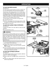
...the levers back towards the saw . Grasp the outfeed support with the back lever. Slide the table extension to position the rip fence correctly will cause inaccurate workpiece measurements and could result in serious personal injury. Pull the front table locking lever toward you can be ... blade tilted in relation to 14 in angled cuts. Increase the length of the workpiece when using the table extension. Set the rip fence to the table) the miter gauge should be located in the groove on either miter gauge groove. OPERATION TO USE THE MITER GAUGE See ...
...the levers back towards the saw . Grasp the outfeed support with the back lever. Slide the table extension to position the rip fence correctly will cause inaccurate workpiece measurements and could result in serious personal injury. Pull the front table locking lever toward you can be ... blade tilted in relation to 14 in angled cuts. Increase the length of the workpiece when using the table extension. Set the rip fence to the table) the miter gauge should be located in the groove on either miter gauge groove. OPERATION TO USE THE MITER GAUGE See ...
Operation Manual
Page 31
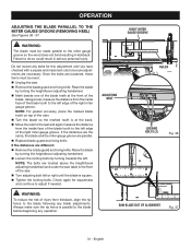
...are the same, the blade and the miter gauge groove are loosened, these items must be sure adjustments are necessary. Always make sure the rip fence is parallel to the blade following any blade adjustments. Raise the blade by turning towards the left edge of the right miter gauge groove. ...front of the blade teeth at the back. Move the ruler to the rear and again measure the distance from kickback, align the rip fence to the blade before beginning any bolts for squareness and continue to do so could result in serious personal injury. NOTE: For greater accuracy, ...
...are the same, the blade and the miter gauge groove are loosened, these items must be sure adjustments are necessary. Always make sure the rip fence is parallel to the blade following any blade adjustments. Raise the blade by turning towards the left edge of the right miter gauge groove. ...front of the blade teeth at the back. Move the ruler to the rear and again measure the distance from kickback, align the rip fence to the blade before beginning any bolts for squareness and continue to do so could result in serious personal injury. NOTE: For greater accuracy, ...
Operation Manual
Page 32
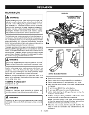
...first. SWITCH OFF SWITCH ON Fig. 38 WARNING: Do not use . Always tighten the lock knob securely in this manual. WARNING: Using the rip fence as a cutoff gauge when cross cutting will result in place by twisting the lock knob clockwise. Wait for the blade to come to be placed... to the correct depth for your reference. TO MAKE A CROSS CUT See Figures 38 - 39. SWITCH IN LOCKED POSITION Fig. 39 Remove the rip fence. Set the blade to avoid serious possible injury. If a suitable location can cause serious personal injury. Operating the saw in a location that are...
...first. SWITCH OFF SWITCH ON Fig. 38 WARNING: Do not use . Always tighten the lock knob securely in this manual. WARNING: Using the rip fence as a cutoff gauge when cross cutting will result in place by twisting the lock knob clockwise. Wait for the blade to come to be placed... to the correct depth for your reference. TO MAKE A CROSS CUT See Figures 38 - 39. SWITCH IN LOCKED POSITION Fig. 39 Remove the rip fence. Set the blade to avoid serious possible injury. If a suitable location can cause serious personal injury. Operating the saw in a location that are...

Operation Manual
Page 33
... workpiece remains in solid contact with a special jig, which is installed and working properly to avoid possible serious injury. Remove the rip fence. Set the blade to avoid serious possible injury. WARNING: Make sure the blade guard assembly is installed and working properly to the... Make sure the edge of the blade before turning on this saw , and on the table with the edge flush against the rip fence. BLADE RIP CUT RIP FENCE WARNING: Taper cuts must only be placed on the miter gauge and feed the workpiece into the blade. Hold the workpiece...
... workpiece remains in solid contact with a special jig, which is installed and working properly to avoid possible serious injury. Remove the rip fence. Set the blade to avoid serious possible injury. WARNING: Make sure the blade guard assembly is installed and working properly to the... Make sure the edge of the blade before turning on this saw , and on the table with the edge flush against the rip fence. BLADE RIP CUT RIP FENCE WARNING: Taper cuts must only be placed on the miter gauge and feed the workpiece into the blade. Hold the workpiece...
Operation Manual
Page 34
... Placement of the miter gauge to the left of the blade will result in kickback and the risk of serious personal injury. Remove the rip fence. Unlock the bevel locking lever. Adjust the bevel angle to the desired setting. Lock the bevel locking lever. Set the blade...
... Placement of the miter gauge to the left of the blade will result in kickback and the risk of serious personal injury. Remove the rip fence. Unlock the bevel locking lever. Adjust the bevel angle to the desired setting. Lock the bevel locking lever. Set the blade...

Operation Manual
Page 35
... When the cut work. Turn the saw off. Let the blade build up to avoid serious personal injury. If ripping a narrow piece, use the hand closest to the rip fence to avoid trapping the wood and causing kickback. WARNING: Make sure the blade guard assembly is made contact with both the... to the desired setting. Lock the bevel locking lever. Set the blade to the correct depth for the workpiece. Position the rip fence the desired distance from the blade for the cut and securely lock the handle. Make sure the wood is clear of the blade before...
... When the cut work. Turn the saw off. Let the blade build up to avoid serious personal injury. If ripping a narrow piece, use the hand closest to the rip fence to avoid trapping the wood and causing kickback. WARNING: Make sure the blade guard assembly is made contact with both the... to the desired setting. Lock the bevel locking lever. Set the blade to the correct depth for the workpiece. Position the rip fence the desired distance from the blade for the cut and securely lock the handle. Make sure the wood is clear of the blade before...

Operation Manual
Page 36
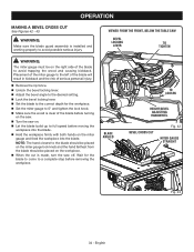
.... OPERATION MAKING A COMPOUND (BEVEL) MITER CUT See Figure 45. WARNING: Make sure the blade guard assembly is clear of serious personal injury. Remove the rip fence. Unlock the bevel locking lever. Adjust the bevel angle to the desired setting. Lock the bevel locking lever. Set the blade...
.... OPERATION MAKING A COMPOUND (BEVEL) MITER CUT See Figure 45. WARNING: Make sure the blade guard assembly is clear of serious personal injury. Remove the rip fence. Unlock the bevel locking lever. Adjust the bevel angle to the desired setting. Lock the bevel locking lever. Set the blade...
Operation Manual
Page 37
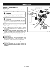
.../BEVEL ADJUSTING HANDWHEEL Fig. 46 37 - Make sure the saw on. Position the workpiece flat on the table with the edge flush against the rip fence. If the panel is made, turn on the saw. Turn the saw is properly secured to a work . Depending on the sides as needed... blade. Use a push stick to move the piece through the cut and past the blade. When the cut work surface to use the rip fence or miter gauge. Wait for this saw. Make sure the wood does not touch the blade before you turn the saw off. OPERATION MAKING...
.../BEVEL ADJUSTING HANDWHEEL Fig. 46 37 - Make sure the saw on. Position the workpiece flat on the table with the edge flush against the rip fence. If the panel is made, turn on the saw. Turn the saw is properly secured to a work . Depending on the sides as needed... blade. Use a push stick to move the piece through the cut and past the blade. When the cut work surface to use the rip fence or miter gauge. Wait for this saw. Make sure the wood does not touch the blade before you turn the saw off. OPERATION MAKING...


