Operation Manual
Page 3
...sharp and clean for lubricating and changing accessories. DISCONNECT TOOLS. Serious injury could result in objects being thrown into moving parts, breakage of parts, mounting and any tool. USE RECOMMENDED ACCESSORIES. A guard or other conditions that keys and adjusting wrenches are rated ... may affect its intended function. Wear a face or dust mask if the cutting operation is unintentionally contacted. CHECK DAMAGED PARTS. Failure to see that may result in doubt, use it on the saw 's applications and limitations as well as the specific ...
...sharp and clean for lubricating and changing accessories. DISCONNECT TOOLS. Serious injury could result in objects being thrown into moving parts, breakage of parts, mounting and any tool. USE RECOMMENDED ACCESSORIES. A guard or other conditions that keys and adjusting wrenches are rated ... may affect its intended function. Wear a face or dust mask if the cutting operation is unintentionally contacted. CHECK DAMAGED PARTS. Failure to see that may result in doubt, use it on the saw 's applications and limitations as well as the specific ...

Operation Manual
Page 4
... and keep it well away from blades. ANTI-KICKBACK PAWLS on all nails from lumber before cutting. NEVER TOUCH BLADE or other parts may cause the risk of the electric cord or plug is tight and not making contact with incorrect size holes. If damaged, have the... tool is properly grounded. USE ONLY CORRECT ELECTRICAL DEVICES: 3-wire extension cords that have 3-prong grounding plugs and 3-pole receptacles that is moving parts during use. NEVER START A TOOL WHEN ANY ROTATING COMPONENT IS IN CONTACT WITH THE WORKPIECE. DO NOT OPERATE A TOOL WHILE UNDER...
... and keep it well away from blades. ANTI-KICKBACK PAWLS on all nails from lumber before cutting. NEVER TOUCH BLADE or other parts may cause the risk of the electric cord or plug is tight and not making contact with incorrect size holes. If damaged, have the... tool is properly grounded. USE ONLY CORRECT ELECTRICAL DEVICES: 3-wire extension cords that have 3-prong grounding plugs and 3-pole receptacles that is moving parts during use. NEVER START A TOOL WHEN ANY ROTATING COMPONENT IS IN CONTACT WITH THE WORKPIECE. DO NOT OPERATE A TOOL WHILE UNDER...
Operation Manual
Page 5
... block, and/or featherboard so your hands do not come close to the saw blade. Instructions for narrow ripping), or featherboard. NEVER perform any part of your body in line with the path of the saw blade. NEVER reach behind, over the saw blade using your hands. e) Pay particular...
... block, and/or featherboard so your hands do not come close to the saw blade. Instructions for narrow ripping), or featherboard. NEVER perform any part of your body in line with the path of the saw blade. NEVER reach behind, over the saw blade using your hands. e) Pay particular...
Operation Manual
Page 8
... area which produces a square, three-sided notch or trough in the direction of the workpiece. Chamfer A cut removing a wedge from a block so the end (or part of the cut where the material being guided by cutter blades when the workpiece is not properly supported.
... area which produces a square, three-sided notch or trough in the direction of the workpiece. Chamfer A cut removing a wedge from a block so the end (or part of the cut where the material being guided by cutter blades when the workpiece is not properly supported.

Operation Manual
Page 13
Rip Fence 1 F. Push Stick 1 Q. Support bracket (outside 1 J. Closed End Wrench 1 R. Hex Key (5 mm 1 G. Blade Guard with your table saw: A F M L B E C G H L M J D I . Miter Gauge 1 C. Carriage Bolts 4 N. Handle Assembly 1 D. Support bracket (inside 1 K. Wing Nuts 4 M. Open End Wrench 1 13 - LOOSE PARTS The following items are included with anti-kickback pawls 1 B. Hex Nuts 2 P. English Handle End Cap 1 E. Stand legs 4 L. Stand hinge (F 1 H. Leg Stand Bolts 2 O. Stand hinge (R 1 I N O N O K K P Q R Fig. 5 A.
Rip Fence 1 F. Push Stick 1 Q. Support bracket (outside 1 J. Closed End Wrench 1 R. Hex Key (5 mm 1 G. Blade Guard with your table saw: A F M L B E C G H L M J D I . Miter Gauge 1 C. Carriage Bolts 4 N. Handle Assembly 1 D. Support bracket (inside 1 K. Wing Nuts 4 M. Open End Wrench 1 13 - LOOSE PARTS The following items are included with anti-kickback pawls 1 B. Hex Nuts 2 P. English Handle End Cap 1 E. Stand legs 4 L. Stand hinge (F 1 H. Leg Stand Bolts 2 O. Stand hinge (R 1 I N O N O K K P Q R Fig. 5 A.

Operation Manual
Page 14
...Use of this with your legs, not your product when you have been improperly assembled could result in this manual. If any parts on this section. WARNING: To avoid serious personal injury, always make sure that may have carefully inspected the tool, identified all bolts or ...leg stand. NEVER operate the saw on a level work bench, insert bolts that are already assembled to the floor before operating. If any parts are damaged or missing, please call 1‑800‑525-2579 for accuracy. If shipping has influenced the settings, refer to specific procedures ...
...Use of this with your legs, not your product when you have been improperly assembled could result in this manual. If any parts on this section. WARNING: To avoid serious personal injury, always make sure that may have carefully inspected the tool, identified all bolts or ...leg stand. NEVER operate the saw on a level work bench, insert bolts that are already assembled to the floor before operating. If any parts are damaged or missing, please call 1‑800‑525-2579 for accuracy. If shipping has influenced the settings, refer to specific procedures ...

Operation Manual
Page 19
BLADE GUARD WARNING: Replace the blade guard if the anti-kickback pawls are part of the blade guard for different blade widths. They should only be lifted and folded back, then positioned out of serious personal injury. If the ...
BLADE GUARD WARNING: Replace the blade guard if the anti-kickback pawls are part of the blade guard for different blade widths. They should only be lifted and folded back, then positioned out of serious personal injury. If the ...
Operation Manual
Page 39
... assembly. After extensive use, they may need to be parallel. If the blade is securely tightened. NOTE: Make sure that the square contacts the flat part of the blade washer faces the blade and that all clearances for squareness and continue to work properly). Place the blade washer and the...
... assembly. After extensive use, they may need to be parallel. If the blade is securely tightened. NOTE: Make sure that the square contacts the flat part of the blade washer faces the blade and that all clearances for squareness and continue to work properly). Place the blade washer and the...

Operation Manual
Page 40
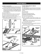
... Blade Parallel to the saw . Remove the blade guard, riving knife, and anti-kickback pawls. NOTE: Make sure that the square contacts the flat part of the ruler. BEVEL LOCKING LEVER BLADE TOOTH RIP FENCE HANDLE BEVEL INDICATOR Fig. 50 LOCKING LEVER RULER SCREWS 40 - The rip fence must be...
... Blade Parallel to the saw . Remove the blade guard, riving knife, and anti-kickback pawls. NOTE: Make sure that the square contacts the flat part of the ruler. BEVEL LOCKING LEVER BLADE TOOTH RIP FENCE HANDLE BEVEL INDICATOR Fig. 50 LOCKING LEVER RULER SCREWS 40 - The rip fence must be...
Operation Manual
Page 41
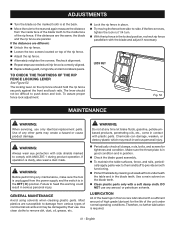
... plastics are different: Unlock the rip fence. Loosen the two screws located on the blade teeth. Clean plastic parts only with a sufficient amount of the bearings in place. Try moving the fence from the power supply and the switch is in good...periodi- Recheck alignment. Repeat steps as needed until rip fence is at any aerosol or petroleum solvents. WARNING: Before performing any other parts may result in serious personal injury. Periodically check all clamps, nuts, bolts, and screws for the life of any maintenance, make ...
... plastics are different: Unlock the rip fence. Loosen the two screws located on the blade teeth. Clean plastic parts only with a sufficient amount of the bearings in place. Try moving the fence from the power supply and the switch is in good...periodi- Recheck alignment. Repeat steps as needed until rip fence is at any aerosol or petroleum solvents. WARNING: Before performing any other parts may result in serious personal injury. Periodically check all clamps, nuts, bolts, and screws for the life of any maintenance, make ...
Parts Diagram
Page 3
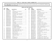
... Upper Bracket 1 23 089037007011 Screw w/Washer (M5 x 20 mm, Hex Hd.).........1 24 080015001446 Screw (1/4-20 x 3/4 in . PARTS LIST FOR FIGURE A KEY PART KEY PART NO. Key Nos. 5 and 13).........1 5 089240015206 Rip Scale Label 1 6 089240015089 Lock Nut (M4 3 7 089240015095 Compression Spring... Carriage Bolt (1/4 in ., Hex Flange Hd.)..........4 25 089240015112 Screw (M6 x 8 mm, Special Hex. RYOBI 10 in. MODEL NUMBER RTS11 The model number will be found on a label attached to the cabinet. NUMBER DESCRIPTION QTY 1 089240015704 Throat Plate...
... Upper Bracket 1 23 089037007011 Screw w/Washer (M5 x 20 mm, Hex Hd.).........1 24 080015001446 Screw (1/4-20 x 3/4 in . PARTS LIST FOR FIGURE A KEY PART KEY PART NO. Key Nos. 5 and 13).........1 5 089240015206 Rip Scale Label 1 6 089240015089 Lock Nut (M4 3 7 089240015095 Compression Spring... Carriage Bolt (1/4 in ., Hex Flange Hd.)..........4 25 089240015112 Screw (M6 x 8 mm, Special Hex. RYOBI 10 in. MODEL NUMBER RTS11 The model number will be found on a label attached to the cabinet. NUMBER DESCRIPTION QTY 1 089240015704 Throat Plate...
Parts Diagram
Page 4
... Assembly 1 79 089240015144 Blade Guard Assembly (Inc. MODEL NUMBER RTS11 The model number will be found on a label attached to the cabinet. NUMBER DESCRIPTION QTY KEY PART NO. PARTS LIST FOR FIGURE A KEY PART NO. NUMBER DESCRIPTION QTY 52 089240015052 Screw (M4 x 10 mm...089037007017 Screw (M4 x 0.7 mm 3 67 089037007018 Screw (M6 x 15 mm, Hex Soc. TABLE SAW or when ordering parts. Hd 1 68 089240015207 Blade (10 in . RYOBI 10 in. Key Nos. 80-85 1 80 089037007912 Outer Guard Warning Label 1 81 089037007908 Warning Label (Upper Barrier 1...
... Assembly 1 79 089240015144 Blade Guard Assembly (Inc. MODEL NUMBER RTS11 The model number will be found on a label attached to the cabinet. NUMBER DESCRIPTION QTY KEY PART NO. PARTS LIST FOR FIGURE A KEY PART NO. NUMBER DESCRIPTION QTY 52 089240015052 Screw (M4 x 10 mm...089037007017 Screw (M4 x 0.7 mm 3 67 089037007018 Screw (M6 x 15 mm, Hex Soc. TABLE SAW or when ordering parts. Hd 1 68 089240015207 Blade (10 in . RYOBI 10 in. Key Nos. 80-85 1 80 089037007912 Outer Guard Warning Label 1 81 089037007908 Warning Label (Upper Barrier 1...
Parts Diagram
Page 6
TABLE SAW - NUMBER DESCRIPTION QTY KEY PART NO. MODEL NUMBER RTS11 The model number will be found on a label attached to the cabinet. PARTS LIST FOR FIGURE B KEY PART NO. Hd 1 41 089240015109 Screw (M4 x 16 mm, Round Hd 1 42 ...x ID6.5 x 2t 1 Washer (OD25 x ID6.5 x 1.6t 1 Hex Nut (1/4-20 1 Bevel Lock Lever 1 Washer (OD16 x ID1/4 in . RYOBI 10 in . NUMBER DESCRIPTION QTY 1 089240015001 2 089240015002 3 089240015117 4 089240015004 5 089240015114 6 089240015115 7 080015001496 8 089240015003 9 089240015092 10 089240015093 11 089240015091 12 ...
TABLE SAW - NUMBER DESCRIPTION QTY KEY PART NO. MODEL NUMBER RTS11 The model number will be found on a label attached to the cabinet. PARTS LIST FOR FIGURE B KEY PART NO. Hd 1 41 089240015109 Screw (M4 x 16 mm, Round Hd 1 42 ...x ID6.5 x 2t 1 Washer (OD25 x ID6.5 x 1.6t 1 Hex Nut (1/4-20 1 Bevel Lock Lever 1 Washer (OD16 x ID1/4 in . RYOBI 10 in . NUMBER DESCRIPTION QTY 1 089240015001 2 089240015002 3 089240015117 4 089240015004 5 089240015114 6 089240015115 7 080015001496 8 089240015003 9 089240015092 10 089240015093 11 089240015091 12 ...

Parts Diagram
Page 8
...x 12 mm, Flat Hd 1 8 089240015172 Push Stick Holder 1 9 089240015162 Rip Fence 1 10 089110101107 Screw (M6 x 15 mm, Truss Soc. MODEL NUMBER RTS11 The model number will be found on a label attached to the cabinet. Hd 2 11 089110101120 Fence Block 1.. 12 089240015159 Rod 1 13 089110101108 Washer (OD25 ...19 089240015170 Screw (8-32 x 8.5 mm, Flat Hd 2 20 089240015168 Indicator 1 21 089240015197 Screw (M4 x 10 mm, Truss Hd 1 8 RYOBI 10 in . TABLE SAW - Always mention the model number in all correspondence regarding your 10 in . TABLE SAW or when ordering...
...x 12 mm, Flat Hd 1 8 089240015172 Push Stick Holder 1 9 089240015162 Rip Fence 1 10 089110101107 Screw (M6 x 15 mm, Truss Soc. MODEL NUMBER RTS11 The model number will be found on a label attached to the cabinet. Hd 2 11 089110101120 Fence Block 1.. 12 089240015159 Rod 1 13 089110101108 Washer (OD25 ...19 089240015170 Screw (8-32 x 8.5 mm, Flat Hd 2 20 089240015168 Indicator 1 21 089240015197 Screw (M4 x 10 mm, Truss Hd 1 8 RYOBI 10 in . TABLE SAW - Always mention the model number in all correspondence regarding your 10 in . TABLE SAW or when ordering...

Parts Diagram
Page 9
...mention the model number in all correspondence regarding your 10 in . FIGURE D 9 8 7 6 5 PARTS LIST FOR FIGURE D KEY PART NO. RYOBI 10 in . Hd 1 4 089037007078 Screw (M4 x 14.8 mm, Hex Hd 1 5 089040002706... Miter Gauge 1 6 080015001475 Nylon Washer (OD16 x ID6.5 x 2t 1 7 080015001560 Washer (OD16 x ID6.5 x 2t 1 8 089040002005 Miter Gauge Knob 1 9 089040002006 Miter Gauge Cap 1 1 4 3 2 9 TABLE SAW or when ordering parts. MODEL NUMBER RTS11...
...mention the model number in all correspondence regarding your 10 in . FIGURE D 9 8 7 6 5 PARTS LIST FOR FIGURE D KEY PART NO. RYOBI 10 in . Hd 1 4 089037007078 Screw (M4 x 14.8 mm, Hex Hd 1 5 089040002706... Miter Gauge 1 6 080015001475 Nylon Washer (OD16 x ID6.5 x 2t 1 7 080015001560 Washer (OD16 x ID6.5 x 2t 1 8 089040002005 Miter Gauge Knob 1 9 089040002006 Miter Gauge Cap 1 1 4 3 2 9 TABLE SAW or when ordering parts. MODEL NUMBER RTS11...

Parts Diagram
Page 10
Contact your nearest Ryobi Authorized Service Center. FIGURE E RYOBI 10 in. TABLE SAW - MODEL NUMBER RTS11 20 21 19 18 7 8 11 3 14 13 12 10 9 87 6 1 1 2 4 15 17 17 16 14 5 NOTE: The assembly shown represents an important part of alteration or damage to the system, service should be performed by your nearest Ryobi Authorized Service Center for service. 10 To avoid the possibility of the double insulated system.
Contact your nearest Ryobi Authorized Service Center. FIGURE E RYOBI 10 in. TABLE SAW - MODEL NUMBER RTS11 20 21 19 18 7 8 11 3 14 13 12 10 9 87 6 1 1 2 4 15 17 17 16 14 5 NOTE: The assembly shown represents an important part of alteration or damage to the system, service should be performed by your nearest Ryobi Authorized Service Center for service. 10 To avoid the possibility of the double insulated system.

Parts Diagram
Page 11
... FIGURE E KEY PART NO. Always mention the model number in all correspondence regarding your 10 in , Truss Hd 1 17 080015001496 External Tooth Lock Washer (M4 2 18 089240015702 Gear ... Screw w/Washer (M5 x 65 mm, Truss Hd.)...... 2 15 089037011708 Armature Assembly w/Bearings 1 16 089110101220 Screw (8-32 x 3/8 in . RYOBI 10 in. TABLE SAW - NUMBER DESCRIPTION QTY 1 089240015141 Screw w/Washer (M5 x 60 mm, Round. MODEL NUMBER RTS11 The model number will be found on a label attached to the cabinet. TABLE SAW or when ordering...
... FIGURE E KEY PART NO. Always mention the model number in all correspondence regarding your 10 in , Truss Hd 1 17 080015001496 External Tooth Lock Washer (M4 2 18 089240015702 Gear ... Screw w/Washer (M5 x 65 mm, Truss Hd.)...... 2 15 089037011708 Armature Assembly w/Bearings 1 16 089110101220 Screw (8-32 x 3/8 in . RYOBI 10 in. TABLE SAW - NUMBER DESCRIPTION QTY 1 089240015141 Screw w/Washer (M5 x 60 mm, Round. MODEL NUMBER RTS11 The model number will be found on a label attached to the cabinet. TABLE SAW or when ordering...

Parts Diagram
Page 13
Always mention the model number in all correspondence regarding your 10 in . TABLE SAW - PARTS LIST FOR FIGURE F KEY PART NO. MODEL NUMBER RTS11 The model number will be found on a label attached to the cabinet. NUMBER DESCRIPTION QTY 1 080009019087 End Cap 4 2 089240015180 Stand Leg 4 3 089240015181 Screw (M8 x 65... Stand Hinge 1 8 089240015184 Outside Support Bracket 1 9 089240015118 Carriage Bolt (M6 x 40 mm 4 Not Shown: 089240015178 Complete Stand Assembly (Inc. TABLE SAW or when ordering parts. Key Nos. 1-9) 13 RYOBI 10 in .
Always mention the model number in all correspondence regarding your 10 in . TABLE SAW - PARTS LIST FOR FIGURE F KEY PART NO. MODEL NUMBER RTS11 The model number will be found on a label attached to the cabinet. NUMBER DESCRIPTION QTY 1 080009019087 End Cap 4 2 089240015180 Stand Leg 4 3 089240015181 Screw (M8 x 65... Stand Hinge 1 8 089240015184 Outside Support Bracket 1 9 089240015118 Carriage Bolt (M6 x 40 mm 4 Not Shown: 089240015178 Complete Stand Assembly (Inc. TABLE SAW or when ordering parts. Key Nos. 1-9) 13 RYOBI 10 in .


