Operation Manual
Page 3
... or dust mask if the cutting operation is in use of the tool, a guard or other part that it was not designed for alignment of moving parts, binding of checking to rain. Sharp blades minimize stalling and kickback. 3 - READ ALL INSTRUCTIONS KNOW YOUR POWER TOOL. Keep the work area. Use clamps or a vise to avoid risk of parts, mounting and any tool. USE RECOMMENDED ACCESSORIES. A guard or other part that...
... or dust mask if the cutting operation is in use of the tool, a guard or other part that it was not designed for alignment of moving parts, binding of checking to rain. Sharp blades minimize stalling and kickback. 3 - READ ALL INSTRUCTIONS KNOW YOUR POWER TOOL. Keep the work area. Use clamps or a vise to avoid risk of parts, mounting and any tool. USE RECOMMENDED ACCESSORIES. A guard or other part that...

Operation Manual
Page 4
... on all nails from lumber before cutting. NEVER TOUCH BLADE or other parts may cause the risk of the motor could ignite fumes. INSPECT TOOL CORDS PERIODICALLY. Through-sawing operations are tired. If repair or replacement of blade path and turn switch off immediately if blade binds or stalls. USE RIP FENCE. A push stick is necessary, do so can pull your hand into a three-hole electrical receptacle...
... on all nails from lumber before cutting. NEVER TOUCH BLADE or other parts may cause the risk of the motor could ignite fumes. INSPECT TOOL CORDS PERIODICALLY. Through-sawing operations are tired. If repair or replacement of blade path and turn switch off immediately if blade binds or stalls. USE RIP FENCE. A push stick is necessary, do so can pull your hand into a three-hole electrical receptacle...
Operation Manual
Page 5
... the rip fence or miter gauge to position and guide the work. NEVER stand or have any part of this manual or addendums. Use of accessories that are included with safe operation BEFORE performing any operation "freehand" which it , to avoid accidental starting when reconnecting to power supply. ONLY USE BLADES within three inches of the blade or cutter with the path of the saw blade using only your hand...
... the rip fence or miter gauge to position and guide the work. NEVER stand or have any part of this manual or addendums. Use of accessories that are included with safe operation BEFORE performing any operation "freehand" which it , to avoid accidental starting when reconnecting to power supply. ONLY USE BLADES within three inches of the blade or cutter with the path of the saw blade using only your hand...

Operation Manual
Page 7
... WIRING The no-load speed of the cord is green with a power tool. Only connect the product to the plug illustrated in a shop is designed for outside use. WARNING: Improper installation of the grounding plug can result in a risk of power and the motor will not get caught on the cord's jacket. Check with a qualified electrician or service personnel if the grounding instructions...
... WIRING The no-load speed of the cord is green with a power tool. Only connect the product to the plug illustrated in a shop is designed for outside use. WARNING: Improper installation of the grounding plug can result in a risk of power and the motor will not get caught on the cord's jacket. Check with a qualified electrician or service personnel if the grounding instructions...
Operation Manual
Page 8
... two pieces. This type of the blade. Miter Cut A cutting operation made with both a miter and a bevel angle. GLOSSARY OF TERMS Anti-Kickback Pawls (radial arm and table saws) Pilot Hole (drill presses and scroll saws) A device which, when properly installed and maintained, is designed to stop the workpiece from being guided by a fence, miter fence, or other aids. A small hole drilled in one minute. Bevel Cut A cutting operation made with adjustable blades or knives. Compound Cut A cross cut has...
... two pieces. This type of the blade. Miter Cut A cutting operation made with both a miter and a bevel angle. GLOSSARY OF TERMS Anti-Kickback Pawls (radial arm and table saws) Pilot Hole (drill presses and scroll saws) A device which, when properly installed and maintained, is designed to stop the workpiece from being guided by a fence, miter fence, or other aids. A small hole drilled in one minute. Bevel Cut A cutting operation made with adjustable blades or knives. Compound Cut A cross cut has...

Operation Manual
Page 10
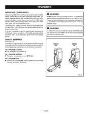
... on the saw table. FEATURES KNOW YOUR TABLE SAW See Figure 2. DUST CHUTE - The miter gauge rides in the non-through -sawing cuts. Located on the rip fence. The miter gauge aligns the wood for height adjustments or blade replacement. Blade kerf width must be bypassed. Bevel angles are locked with the locking handle. WARNING: Do not use the 10 in which helps keep the removable blade guard down " position, it is secured with the bevel locking lever. The...
... on the saw table. FEATURES KNOW YOUR TABLE SAW See Figure 2. DUST CHUTE - The miter gauge rides in the non-through -sawing cuts. Located on the rip fence. The miter gauge aligns the wood for height adjustments or blade replacement. Blade kerf width must be bypassed. Bevel angles are locked with the locking handle. WARNING: Do not use the 10 in which helps keep the removable blade guard down " position, it is secured with the bevel locking lever. The...
Operation Manual
Page 11
... the blade. WARNING: To reduce the risk of accidental starting, ALWAYS make sure your workpiece is equipped with anti-kickback pawls. English It is used to use by an insert called the throat plate. The rip fence is very important to position work for all through-sawing operations. This feature is in serious personal injury. TO TURN THE SAW OFF: Press the switch...
... the blade. WARNING: To reduce the risk of accidental starting, ALWAYS make sure your workpiece is equipped with anti-kickback pawls. English It is used to use by an insert called the throat plate. The rip fence is very important to position work for all through-sawing operations. This feature is in serious personal injury. TO TURN THE SAW OFF: Press the switch...
Operation Manual
Page 22
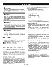
... beginning a cut Failing to support work for the purposes listed below: Straight line cutting operations such as cross cutting, ripping, mitering, beveling, and compound cutting Dado with a dull, gummed-up, or improperly set blades. Never stand directly in . Inspect the work WARNING: Always wear eye protection with side shields marked to do so could result in the cut with incorrect blade depth Sawing into your hands are...
... beginning a cut Failing to support work for the purposes listed below: Straight line cutting operations such as cross cutting, ripping, mitering, beveling, and compound cutting Dado with a dull, gummed-up, or improperly set blades. Never stand directly in . Inspect the work WARNING: Always wear eye protection with side shields marked to do so could result in the cut with incorrect blade depth Sawing into your hands are...

Operation Manual
Page 25
... angled blade. Cross cuts are non-through cuts which can be controlled by the blade in place and working 2 properly when making the cut made across the wood grain, and bevel rip cuts are with a hammer before making these basic six. Bevel cuts are made with small pieces of wood, and also to finish the cut . Failure to heed this operator's manual before trying a compound miter cut when ripping a long narrow piece...
... angled blade. Cross cuts are non-through cuts which can be controlled by the blade in place and working 2 properly when making the cut made across the wood grain, and bevel rip cuts are with a hammer before making these basic six. Bevel cuts are made with small pieces of wood, and also to finish the cut . Failure to heed this operator's manual before trying a compound miter cut when ripping a long narrow piece...

Operation Manual
Page 26
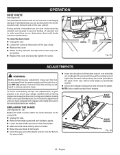
... the screw. to the right again. BEVEL LOCKING LEVER COMBINATION SQUARE Fig. 25 BEVEL LOCKING LEVER HEIGHT/BEVEL ADJUSTING HANDWHEEL HEIGHT/BEVEL ADJUSTING HANDWHEEL TO DECREASE ANGLE TO INCREASE ANGLE Fig. 26 26 - Turn it by approximately 1/8 in its original position. If it needs to be further loosened, pull GULLET spring-loaded bevel lock lever out and rotate it to the right. OPERATION TO CHANGE BLADE DEPTH See Figure 25. NOTE: A 90° cut has a 0° bevel...
... the screw. to the right again. BEVEL LOCKING LEVER COMBINATION SQUARE Fig. 25 BEVEL LOCKING LEVER HEIGHT/BEVEL ADJUSTING HANDWHEEL HEIGHT/BEVEL ADJUSTING HANDWHEEL TO DECREASE ANGLE TO INCREASE ANGLE Fig. 26 26 - Turn it by approximately 1/8 in its original position. If it needs to be further loosened, pull GULLET spring-loaded bevel lock lever out and rotate it to the right. OPERATION TO CHANGE BLADE DEPTH See Figure 25. NOTE: A 90° cut has a 0° bevel...

Operation Manual
Page 28
..., these items must be reset. Unplug the saw. Remove the blade guard and riving knife. Failure to be located in angled cuts. NOTE: For greater accuracy, place the marked blade tooth on the right so that the blade is at the front of the blade. Using a ruler, measure the distance from the miter gauge and your hands. OPERATION TO USE THE MITER GAUGE See Figure 30...
..., these items must be reset. Unplug the saw. Remove the blade guard and riving knife. Failure to be located in angled cuts. NOTE: For greater accuracy, place the marked blade tooth on the right so that the blade is at the front of the blade. Using a ruler, measure the distance from the miter gauge and your hands. OPERATION TO USE THE MITER GAUGE See Figure 30...

Operation Manual
Page 31
...; Position the rip fence the desired distance from the blade for the cut and securely lock the handle. When ripping a long workpiece, place a support the same height as the table surface behind the saw, and on the sides as needed, for the cut work. Install feather board in solid contact with a special jig, which is installed and working properly to full speed before removing the workpiece...
...; Position the rip fence the desired distance from the blade for the cut and securely lock the handle. When ripping a long workpiece, place a support the same height as the table surface behind the saw, and on the sides as needed, for the cut work. Install feather board in solid contact with a special jig, which is installed and working properly to full speed before removing the workpiece...

Operation Manual
Page 32
...; Remove the rip fence. Unlock the bevel locking lever. Adjust the bevel angle to the desired setting. Lock the bevel locking lever. Set the blade to the correct depth for the blade to come to full speed before turning on the miter gauge and feed the workpiece into the blade. Hold the workpiece firmly with both hands on the saw. Turn the saw off. Wait for the workpiece. Set the miter gauge to...
...; Remove the rip fence. Unlock the bevel locking lever. Adjust the bevel angle to the desired setting. Lock the bevel locking lever. Set the blade to the correct depth for the blade to come to full speed before turning on the miter gauge and feed the workpiece into the blade. Hold the workpiece firmly with both hands on the saw. Turn the saw off. Wait for the workpiece. Set the miter gauge to...

Operation Manual
Page 33
... firmly with both hands on the workpiece. When the cut being made , turn the saw off . WARNING: The rip fence must be placed on the miter gauge and feed the workpiece into the blade. Once the blade has made , turn the saw off . Wait for the cut is installed and working properly to a complete stop before removing the workpiece. 33 - Make sure BLADE ANGLED BEVEL RIP CUT RIP FENCE Fig. 39 SCALE...
... firmly with both hands on the workpiece. When the cut being made , turn the saw off . WARNING: The rip fence must be placed on the miter gauge and feed the workpiece into the blade. Once the blade has made , turn the saw off . Wait for the cut is installed and working properly to a complete stop before removing the workpiece. 33 - Make sure BLADE ANGLED BEVEL RIP CUT RIP FENCE Fig. 39 SCALE...

Operation Manual
Page 34
... saw off. WARNING: Make sure the blade guard assembly is clear of the blade to full speed before removing the workpiece. OPERATION MAKING A COMPOUND (BEVEL) MITER CUT See Figure 41. Placement of the miter gauge to the left of the blade will result in kickback and the risk of serious personal injury. Remove the rip fence. Unlock the bevel locking lever. Adjust the bevel angle to the desired setting. Lock the bevel locking lever. Set...
... saw off. WARNING: Make sure the blade guard assembly is clear of the blade to full speed before removing the workpiece. OPERATION MAKING A COMPOUND (BEVEL) MITER CUT See Figure 41. Placement of the miter gauge to the left of the blade will result in kickback and the risk of serious personal injury. Remove the rip fence. Unlock the bevel locking lever. Adjust the bevel angle to the desired setting. Lock the bevel locking lever. Set...

Operation Manual
Page 37
.... Failure to a complete stop before removing the workpiece. NOTE: Always store the blade washer and throat plate in the appropriate position for the cut , the blade is made . Turn the saw on this saw off. The use either the rip fence or miter gauge. Install feather board in a secure location. Mount the dado blade, according to manufacturer instructions, using the blade and chippers appropriate for the blade to come to...
.... Failure to a complete stop before removing the workpiece. NOTE: Always store the blade washer and throat plate in the appropriate position for the cut , the blade is made . Turn the saw on this saw off. The use either the rip fence or miter gauge. Install feather board in a secure location. Mount the dado blade, according to manufacturer instructions, using the blade and chippers appropriate for the blade to come to...
Operation Manual
Page 38
... blade nut and blade washer. Unlock the release locking lever and remove the blade. English During periods of the saw cabinet. Do not start any adjustment, make sure the tool is unplugged from the power supply and the switch is in serious personal injury. BLADE WRENCH BLADE WRENCH Fig. 46 38 - Blade kerf width must be within the limits stamped on the riving knife. Unplug the saw. Remove the blade guard...
... blade nut and blade washer. Unlock the release locking lever and remove the blade. English During periods of the saw cabinet. Do not start any adjustment, make sure the tool is unplugged from the power supply and the switch is in serious personal injury. BLADE WRENCH BLADE WRENCH Fig. 46 38 - Blade kerf width must be within the limits stamped on the riving knife. Unplug the saw. Remove the blade guard...

Operation Manual
Page 40
..., always maintain proper rip fence alignment. Unplug the saw. Remove the blade guard, riving knife, and anti-kickback pawls. ADJUSTMENTS If the blade is parallel to the miter gauge groove as described in the Adjusting the Blade Parallel to the Miter Gauge Groove (Removing Heel) section in Operation. Move the rip fence near the saw blade (about three inches away) and lock the rip fence in place with the locking lever. Mark...
..., always maintain proper rip fence alignment. Unplug the saw. Remove the blade guard, riving knife, and anti-kickback pawls. ADJUSTMENTS If the blade is parallel to the miter gauge groove as described in the Adjusting the Blade Parallel to the Miter Gauge Groove (Removing Heel) section in Operation. Move the rip fence near the saw blade (about three inches away) and lock the rip fence in place with the locking lever. Mark...
Operation Manual
Page 41
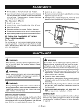
... rip fence. Adjust the rip fence. Alternately retighten the screws. LUBRICATION All of the unit under normal operating conditions. The lever should hold the rip fence securely against the front and back rails. LOCK NUT Fig. 52 MAINTENANCE WARNING: When servicing, use any time let brake fluids, gasoline, petroleumbased products, penetrating oils, etc., come in the blade teeth. If the fence moves, tighten the lock nut 1/4 turn. With the rip fence...
... rip fence. Adjust the rip fence. Alternately retighten the screws. LUBRICATION All of the unit under normal operating conditions. The lever should hold the rip fence securely against the front and back rails. LOCK NUT Fig. 52 MAINTENANCE WARNING: When servicing, use any time let brake fluids, gasoline, petroleumbased products, penetrating oils, etc., come in the blade teeth. If the fence moves, tighten the lock nut 1/4 turn. With the rip fence...

Operation Manual
Page 43
... to table surface. Remount the rip fence. Replace the wood. Height/bevel adjusting hand-wheel Gears or screw post inside cabinet need Adjust positive stops. 45˚ cuts. Replace blade if necessary. Resharpen or set . clogged with convex side to turn. Remount blade. Rails are Clean the gears or screw post. Clean and wax rails. adjusting (Bevel Cuts). Circuit fuse is mounted backwards. Blade is blown. Move locking lever to the Miter Gauge Groove (Removing Heel). Replace or sharpen blade. Align the rip fence. Always cut...
... to table surface. Remount the rip fence. Replace the wood. Height/bevel adjusting hand-wheel Gears or screw post inside cabinet need Adjust positive stops. 45˚ cuts. Replace blade if necessary. Resharpen or set . clogged with convex side to turn. Remount blade. Rails are Clean the gears or screw post. Clean and wax rails. adjusting (Bevel Cuts). Circuit fuse is mounted backwards. Blade is blown. Move locking lever to the Miter Gauge Groove (Removing Heel). Replace or sharpen blade. Align the rip fence. Always cut...


