
English Manual
Page 2
... LIMITATIONS: Any implied warranties granted under this warranty. One World Technologies, Inc. TABLE OF CONTENTS Introduction ...2 � Warranty ...2 General Safety Rules ...3-4 � Specific Safety Rules...4 Safety Rules for Charger ...5 � Symbols...6-7 � Features...8 � Assembly ...9 � Operation...10-15 � Maintenance ...16-19 � Parts Ordering / Service ...20 INTRODUCTION This tool has many features...
... LIMITATIONS: Any implied warranties granted under this warranty. One World Technologies, Inc. TABLE OF CONTENTS Introduction ...2 � Warranty ...2 General Safety Rules ...3-4 � Specific Safety Rules...4 Safety Rules for Charger ...5 � Symbols...6-7 � Features...8 � Assembly ...9 � Operation...10-15 � Maintenance ...16-19 � Parts Ordering / Service ...20 INTRODUCTION This tool has many features...
English Manual
Page 3
...; Do not expose power tools to your mains-operated (corded) power tool or battery-operated (cordless) power tool. Safety equipment such as in . POWER TOOL USE AND CARE Do not force the power tool. Power tools are dangerous in moving parts. If devices are connected and properly used for misalignment or binding of moving parts. If damaged, have the switch on invites accidents. Remove any adapter plugs with charger listed. Do not use on a solid...
...; Do not expose power tools to your mains-operated (corded) power tool or battery-operated (cordless) power tool. Safety equipment such as in . POWER TOOL USE AND CARE Do not force the power tool. Power tools are dangerous in moving parts. If devices are connected and properly used for misalignment or binding of moving parts. If damaged, have the switch on invites accidents. Remove any adapter plugs with charger listed. Do not use on a solid...
English Manual
Page 4
... to stop before inserting battery pack. Holding injury. power tool. Following this rule will ensure that has been dropped or received a sharp blow. when not using only identical replacement parts. GENERAL SAFETY RULES Use the power tool, accessories and tool bits etc., in accordance with these instructions and in the manner intended for the particular type of power tool, taking into account the working conditions and the work by hand or...
... to stop before inserting battery pack. Holding injury. power tool. Following this rule will ensure that has been dropped or received a sharp blow. when not using only identical replacement parts. GENERAL SAFETY RULES Use the power tool, accessories and tool bits etc., in accordance with these instructions and in the manner intended for the particular type of power tool, taking into account the working conditions and the work by hand or...

English Manual
Page 5
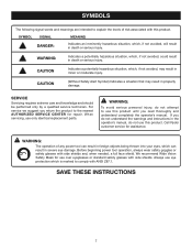
... injury. Before using battery charger, read all instructions listed below : Cord Length (Feet) 25' 50' 100' Cord Size (AWG) 16 16 16 NOTE: AWG = American Wire Gauge Do not operate charger with sharp edges or moving parts or otherwise subjected to reduce the risk of the products and possible injury or damage. SAVE THESE INSTRUCTIONS This manual contains important safety and operating instructions for electrical check to wet...
... injury. Before using battery charger, read all instructions listed below : Cord Length (Feet) 25' 50' 100' Cord Size (AWG) 16 16 16 NOTE: AWG = American Wire Gauge Do not operate charger with sharp edges or moving parts or otherwise subjected to reduce the risk of the products and possible injury or damage. SAVE THESE INSTRUCTIONS This manual contains important safety and operating instructions for electrical check to wet...
English Manual
Page 7
... a qualified service technician. We recommend Wide Vision Safety Mask for repair. WARNING: Indicates a potentially hazardous situation, which , if not avoided, will result in death or serious injury. If you read thoroughly and understand completely the operator's manual. Call Ryobi customer service for assistance. When servicing, use this product until you do not understand the warnings and instructions in the operator's manual, do...
... a qualified service technician. We recommend Wide Vision Safety Mask for repair. WARNING: Indicates a potentially hazardous situation, which , if not avoided, will result in death or serious injury. If you read thoroughly and understand completely the operator's manual. Call Ryobi customer service for assistance. When servicing, use this product until you do not understand the warnings and instructions in the operator's manual, do...
English Manual
Page 8
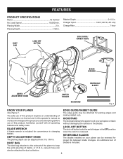
... use of blades is included. 8 vacuum hose can be attached for convenience in . KICKSTAND The kickstand allows the planer to 1/64 in changing blades. Charger Input 120 V, 60 Hz, AC only Charge Rate 1 hour DUST BAG LOCK-OFF BUTTON EDGE GUIDE/ RABBET GUIDE BLADE WRENCH REVERSIBLE BLADES DEPTH ADJUSTMENT KNOB SWITCH TRIGGER KICKSTAND Fig. 1 KNOW YOUR PLANER See Figure 1. Before use of this product, familiarize yourself with all operating features and safety rules. DEPTH ADJUSTMENT KNOB...
... use of blades is included. 8 vacuum hose can be attached for convenience in . KICKSTAND The kickstand allows the planer to 1/64 in changing blades. Charger Input 120 V, 60 Hz, AC only Charge Rate 1 hour DUST BAG LOCK-OFF BUTTON EDGE GUIDE/ RABBET GUIDE BLADE WRENCH REVERSIBLE BLADES DEPTH ADJUSTMENT KNOB SWITCH TRIGGER KICKSTAND Fig. 1 KNOW YOUR PLANER See Figure 1. Before use of this product, familiarize yourself with all operating features and safety rules. DEPTH ADJUSTMENT KNOB...
English Manual
Page 9
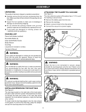
... possible serious injury. To remove the dust bag, grasp the adaptor and pull the dust bag away from the tool when assembling parts. WARNING: Do not attempt to be thrown into your face or eyes, which could cause dust or foreign objects to modify this tool or create accessories not recommended for use with blades installed) Reversible Blades (2) Edge Guide/Rabbet Guide Blade Wrench Dust Bag Lanyard (not included...
... possible serious injury. To remove the dust bag, grasp the adaptor and pull the dust bag away from the tool when assembling parts. WARNING: Do not attempt to be thrown into your face or eyes, which could cause dust or foreign objects to modify this tool or create accessories not recommended for use with blades installed) Reversible Blades (2) Edge Guide/Rabbet Guide Blade Wrench Dust Bag Lanyard (not included...

English Manual
Page 10
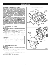
... or safety glasses with side shields when operating tools. See Figure 4. Press down on . Green LED on indicates battery pack is fully charged and charger is normal household voltage, 120 volts, 60 Hz, AC only. Connect the charger to become fully charged, unplug the charger from the power supply. If both the battery pack and charger to be replaced...
... or safety glasses with side shields when operating tools. See Figure 4. Press down on . Green LED on indicates battery pack is fully charged and charger is normal household voltage, 120 volts, 60 Hz, AC only. Connect the charger to become fully charged, unplug the charger from the power supply. If both the battery pack and charger to be replaced...
English Manual
Page 11
... beginning operation. If the charger does not charge your battery pack under normal circumstances. TO INSTALL BATTERY PACK See Figure 5. Place the lock-off button in the tool. It does not occur under normal circumstances, return both the battery pack and charger to come on each side of the tool causes the batteries to your nearest Authorized Service Center for electrical check. TO REMOVE BATTERY...
... beginning operation. If the charger does not charge your battery pack under normal circumstances. TO INSTALL BATTERY PACK See Figure 5. Place the lock-off button in the tool. It does not occur under normal circumstances, return both the battery pack and charger to come on each side of the tool causes the batteries to your nearest Authorized Service Center for electrical check. TO REMOVE BATTERY...

English Manual
Page 12
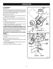
... personal injury. LOCK-OFF BUTTON WORKPIECE DEPTH ADJUSTMENT SCALE 12 (01.464mm) SWITCH TRIGGER Fig. 6 KICKSTAND Fig. 7 DEPTH ADJUSTMENT KNOB Fig. 8 NOTE: The switch automatically locks when not depressed to the left or the right. Turn the depth adjustment knob clockwise to do so could result in use . STARTING/STOPPING THE PLANER See Figure 6. To start the planer: Push the lock-off button in operating condition. OPERATION WARNING: Battery tools are always in...
... personal injury. LOCK-OFF BUTTON WORKPIECE DEPTH ADJUSTMENT SCALE 12 (01.464mm) SWITCH TRIGGER Fig. 6 KICKSTAND Fig. 7 DEPTH ADJUSTMENT KNOB Fig. 8 NOTE: The switch automatically locks when not depressed to the left or the right. Turn the depth adjustment knob clockwise to do so could result in use . STARTING/STOPPING THE PLANER See Figure 6. To start the planer: Push the lock-off button in operating condition. OPERATION WARNING: Battery tools are always in...

English Manual
Page 13
... damage blades. Failure to control the planer. Keep a freshly charged battery available and replace the discharged battery when you have removed the battery. This helps keep an extra set , never individually. Plane slowly and empty the dust bag often. Hold the front handle with your right hand. Always properly support and clamp the work . Apply pressure to avoid hitting nails or any operation. this...
... damage blades. Failure to control the planer. Keep a freshly charged battery available and replace the discharged battery when you have removed the battery. This helps keep an extra set , never individually. Plane slowly and empty the dust bag often. Hold the front handle with your right hand. Always properly support and clamp the work . Apply pressure to avoid hitting nails or any operation. this...
English Manual
Page 14
... downward pressure to chamfer edges of the work , using the knob nut and the carriage head bolt. Tighten the knob bolt and knob nut securely. ATTACHING THE EDGE GUIDE FOR PLANING EDGES See Figure 11. Lock the switch by placing the lock-off button in the front shoe to keep the planer flat at the beginning and the end of boards as shown. Before making rabbet cuts. OPERATION...
... downward pressure to chamfer edges of the work , using the knob nut and the carriage head bolt. Tighten the knob bolt and knob nut securely. ATTACHING THE EDGE GUIDE FOR PLANING EDGES See Figure 11. Lock the switch by placing the lock-off button in the front shoe to keep the planer flat at the beginning and the end of boards as shown. Before making rabbet cuts. OPERATION...

English Manual
Page 15
... using the knob nut and the carriage head bolt. Adjust the edge guide to reach the desired depth. Follow the directions in the Operating the Planer section earlier in Operating the Planer. Cuts should be adjusted by placing the lock-off button in . Hold the edge guide firmly against the edge of the work surface. Hold the edge guide firmly against the edge of the work surface. ATTACHING THE EDGE GUIDE FOR MAKING RABBET CUTS...
... using the knob nut and the carriage head bolt. Adjust the edge guide to reach the desired depth. Follow the directions in the Operating the Planer section earlier in Operating the Planer. Cuts should be adjusted by placing the lock-off button in . Hold the edge guide firmly against the edge of the work surface. Hold the edge guide firmly against the edge of the work surface. ATTACHING THE EDGE GUIDE FOR MAKING RABBET CUTS...
English Manual
Page 16
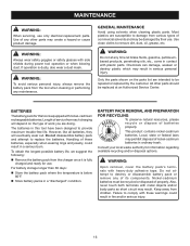
.... Handling of its components. This product contains nickel-cadmium batteries. If operation is below 80°F. Store battery packs in fire and/or serious injury. 16 WARNING: Upon removal, cover the battery pack's terminals with side shields during power tool operation or when blowing dust. Nickel-cadmium batteries must be repaired or replaced by their use. MAINTENANCE WARNING: When servicing, use . Only the parts shown on the type...
.... Handling of its components. This product contains nickel-cadmium batteries. If operation is below 80°F. Store battery packs in fire and/or serious injury. 16 WARNING: Upon removal, cover the battery pack's terminals with side shields during power tool operation or when blowing dust. Nickel-cadmium batteries must be repaired or replaced by their use. MAINTENANCE WARNING: When servicing, use . Only the parts shown on the type...
English Manual
Page 17
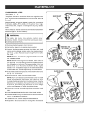
... blade holder using the blade wrench provided. MAINTENANCE CHANGING BLADES See Figures 14 - 16. When one edge becomes dull, the blade can be accurate. If the blades in the planer show signs of a screwdriver. Remove the old blade from the tool. Secure the planer in the same orientation as the screw heads and the flat edge facing the cutter block. Push the blade (to remove the old blade. BLADE CLAMP BLADE WRENCH SCREWS REMOVING...
... blade holder using the blade wrench provided. MAINTENANCE CHANGING BLADES See Figures 14 - 16. When one edge becomes dull, the blade can be accurate. If the blades in the planer show signs of a screwdriver. Remove the old blade from the tool. Secure the planer in the same orientation as the screw heads and the flat edge facing the cutter block. Push the blade (to remove the old blade. BLADE CLAMP BLADE WRENCH SCREWS REMOVING...

English Manual
Page 18
... overtighten the screws. When replacing the belt, use recommended replacement belt only (Part No. 570279002). Remove the battery pack from the tool. Remove the belt cover screws. Remove the belt cover. Force the old belt from both pulleys. Replace the belt cover. Install the belt cover screws and tighten securely. BELT COVER SCREWS Fig. 17 SMALL PULLEY LARGE PULLEY Fig. 18 18 As you turn the belt, pull and work it...
... overtighten the screws. When replacing the belt, use recommended replacement belt only (Part No. 570279002). Remove the battery pack from the tool. Remove the belt cover screws. Remove the belt cover. Force the old belt from both pulleys. Replace the belt cover. Install the belt cover screws and tighten securely. BELT COVER SCREWS Fig. 17 SMALL PULLEY LARGE PULLEY Fig. 18 18 As you turn the belt, pull and work it...
English Manual
Page 19
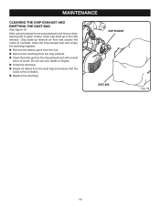
Do not use your hands or fingers. Unzip the dust bag. Empty all debris from the chip exhaust. Clean the build-up in the chip exhaust. After using the planer for an extended period of time or when planing wet or green lumber, chips ... piece of debris. Replace the dust bag. Clean the chip exhaust port and empty the dust bag regularly. Remove the battery pack from the tool. Remove the dust bag from the dust bag and ensure that the collar is free of wood. Chip build-up restricts air flow and causes the motor to overheat. MAINTENANCE...
Do not use your hands or fingers. Unzip the dust bag. Empty all debris from the chip exhaust. Clean the build-up in the chip exhaust. After using the planer for an extended period of time or when planing wet or green lumber, chips ... piece of debris. Replace the dust bag. Clean the chip exhaust port and empty the dust bag regularly. Remove the battery pack from the tool. Remove the dust bag from the dust bag and ensure that the collar is free of wood. Chip build-up restricts air flow and causes the motor to overheat. MAINTENANCE...
English Manual
Page 20
... chemically-treated lumber. Some examples of this type of Authorized Service Centers. • MODEL NO. To reduce your exposure to these chemicals: work in the space provided below. • HOW TO ORDER REPAIR PARTS When ordering repair parts, always give the following information: • MODEL NUMBER P610 • SERIAL NUMBER Ryobi® is a registered trademark of Ryobi Limited used under license. 983000-936 1-30-06 (REV...
... chemically-treated lumber. Some examples of this type of Authorized Service Centers. • MODEL NO. To reduce your exposure to these chemicals: work in the space provided below. • HOW TO ORDER REPAIR PARTS When ordering repair parts, always give the following information: • MODEL NUMBER P610 • SERIAL NUMBER Ryobi® is a registered trademark of Ryobi Limited used under license. 983000-936 1-30-06 (REV...
Repair Sheet
Page 3
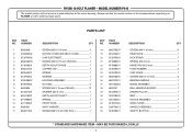
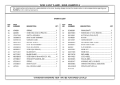
... * SCREW (M3.5 X 16 mm 4 MOTOR COVER AND BELT COVER 1 CHIP EJECTMENT 1 * SCREW (M3.5 X 15 mm PAN HD 1 DEPTH ADJUST KNOB 1 COPPER CAP 1 SPRING 1 WASHER 1 HOUSING ASSEMBLY 1 NUT (M5 2 * SCREW (M4 X 16 mm PAN HD 17 WASHER (ID7.2 mm 1 DEPTH ADJUST SHAFT 1 SPRING 1 FRONT SHOE 1 WAVY WASHER 1 * SCREW (M8 X 9 mm HEX SOC 1 KEY NO. PARTS LIST KEY NO. MAY BE PURCHASED LOCALLY 3 MODEL NUMBER P610 The model number will be found on a plate attached to the motor housing. RYOBI 18 VOLT PLANER...
... * SCREW (M3.5 X 16 mm 4 MOTOR COVER AND BELT COVER 1 CHIP EJECTMENT 1 * SCREW (M3.5 X 15 mm PAN HD 1 DEPTH ADJUST KNOB 1 COPPER CAP 1 SPRING 1 WASHER 1 HOUSING ASSEMBLY 1 NUT (M5 2 * SCREW (M4 X 16 mm PAN HD 17 WASHER (ID7.2 mm 1 DEPTH ADJUST SHAFT 1 SPRING 1 FRONT SHOE 1 WAVY WASHER 1 * SCREW (M8 X 9 mm HEX SOC 1 KEY NO. PARTS LIST KEY NO. MAY BE PURCHASED LOCALLY 3 MODEL NUMBER P610 The model number will be found on a plate attached to the motor housing. RYOBI 18 VOLT PLANER...
Repair Sheet
Page 4
... FLAT WASHER 1 59 540510007 KNOB NUT 1 60 540511008 KNOB BOLT 1 61 940115118 DATA LABEL 1 62 940114135 LOGO LABEL 1 63 940700005 SCALE LABEL 1 64 940230147 WARNING LABEL (ON BASE 1 983000936 OPERATOR'S MANUAL (960223929) 983000936R REPAIR SHEET (REV:00) 03-13-06 * STANDARD HARDWARE ITEM - RYOBI 18 VOLT PLANER - MODEL NUMBER P610 The model number will be found on a plate attached to the motor housing. MAY BE PURCHASED LOCALLY 4 PARTS LIST KEY NO. PART NUMBER...
... FLAT WASHER 1 59 540510007 KNOB NUT 1 60 540511008 KNOB BOLT 1 61 940115118 DATA LABEL 1 62 940114135 LOGO LABEL 1 63 940700005 SCALE LABEL 1 64 940230147 WARNING LABEL (ON BASE 1 983000936 OPERATOR'S MANUAL (960223929) 983000936R REPAIR SHEET (REV:00) 03-13-06 * STANDARD HARDWARE ITEM - RYOBI 18 VOLT PLANER - MODEL NUMBER P610 The model number will be found on a plate attached to the motor housing. MAY BE PURCHASED LOCALLY 4 PARTS LIST KEY NO. PART NUMBER...


