Operation Manual
Page 2
See this fold-out section for all of the figures referenced in the operator's manual. Consulter l'encart à volets afin d'examiner toutes les figures mentionnées dans le manuel d'utilisation. Consulte esta sección desplegable para ver todas las figuras a las que se hace referencia en el manual del operador. ii
See this fold-out section for all of the figures referenced in the operator's manual. Consulter l'encart à volets afin d'examiner toutes les figures mentionnées dans le manuel d'utilisation. Consulte esta sección desplegable para ver todas las figuras a las que se hace referencia en el manual del operador. ii

Operation Manual
Page 6
... not use the lawn mower in damp or wet conditions or operate in moving parts. Don't overreach - English Replace damaged or unevenly worn blades before cleaning the lawn mower, removing the grass catcher, or removing the mulching plug. Replace blade if it was designed. Do not charge lawn mower in rain, or in serious injury or death. Avoid dangerous environment - READ ALL INSTRUCTIONS This cutting machine...
... not use the lawn mower in damp or wet conditions or operate in moving parts. Don't overreach - English Replace damaged or unevenly worn blades before cleaning the lawn mower, removing the grass catcher, or removing the mulching plug. Replace blade if it was designed. Do not charge lawn mower in rain, or in serious injury or death. Avoid dangerous environment - READ ALL INSTRUCTIONS This cutting machine...

Operation Manual
Page 7
... to instruct others who are sure the blade has stopped rotating. If the mower should start key removed from the mower. Battery tools do not have to ricochet back toward the operator. Refer to them frequently and use . Stay behind to avoid tripping or pulling the mower over your battery tool or when changing accessories. The lawn should also be performed by releasing the blade control lever...
... to instruct others who are sure the blade has stopped rotating. If the mower should start key removed from the mower. Battery tools do not have to ricochet back toward the operator. Refer to them frequently and use . Stay behind to avoid tripping or pulling the mower over your battery tool or when changing accessories. The lawn should also be performed by releasing the blade control lever...
Operation Manual
Page 8
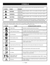
... Keep hands and feet away from blade and cutting area. Keep all children and bystanders at least 100 ft. WARNING: Indicates a hazardous situation, which , if not avoided, will allow you to explain the levels of risk associated with ANSI Z87.1. Some of injury, user must read and understand operator's manual before using this product. SYMBOL NAME DESIGNATION...
... Keep hands and feet away from blade and cutting area. Keep all children and bystanders at least 100 ft. WARNING: Indicates a hazardous situation, which , if not avoided, will allow you to explain the levels of risk associated with ANSI Z87.1. Some of injury, user must read and understand operator's manual before using this product. SYMBOL NAME DESIGNATION...
Operation Manual
Page 9
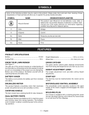
.... MOTOR/BLADE CONTROL ASSEMBLY The motor/blade control assembly, located on the product and in . SYMBOLS Some of the following symbols may prohibit disposal of batteries in . BRUSHLESS MOTOR This product features a brushless motor that covers the rear discharge opening, which allows the mower blade to 3.5 in tandem to deliver consistent power to maximize power and minimize down time during operation. HEIGHT ADJUSTMENT LEVER The height adjustment lever provides cutting height adjustments. English Consult your lawn...
.... MOTOR/BLADE CONTROL ASSEMBLY The motor/blade control assembly, located on the product and in . SYMBOLS Some of the following symbols may prohibit disposal of batteries in . BRUSHLESS MOTOR This product features a brushless motor that covers the rear discharge opening, which allows the mower blade to 3.5 in tandem to deliver consistent power to maximize power and minimize down time during operation. HEIGHT ADJUSTMENT LEVER The height adjustment lever provides cutting height adjustments. English Consult your lawn...

Operation Manual
Page 10
... adjustments or installations with the start key or battery pack until assembly is misuse and could result in the packing list are not assembled to modify this product or create accessories not recommended for use this product until it . PACKING LIST Lawn Mower Start Key Mulching Plug Grass Catcher Operator's Manual UNFOLDING AND ADJUSTING HANDLE ASSEMBLY See Figures 2 - 3. ASSEMBLY UNPACKING This product requires assembly. n Carefully remove the product and any parts on this list...
... adjustments or installations with the start key or battery pack until assembly is misuse and could result in the packing list are not assembled to modify this product or create accessories not recommended for use this product until it . PACKING LIST Lawn Mower Start Key Mulching Plug Grass Catcher Operator's Manual UNFOLDING AND ADJUSTING HANDLE ASSEMBLY See Figures 2 - 3. ASSEMBLY UNPACKING This product requires assembly. n Carefully remove the product and any parts on this list...

Operation Manual
Page 11
... the handle to a low-cutting position. When shipped, the wheels on the mower are set to the front of the mower. Reinstall start key and battery pack when you are ready to the height best suited for your lawn. English INSTALLING THE MULCHING PLUG (FOR MULCHING OPERATION) See Figure 4. SETTING BLADE HEIGHT See Figure 7. INSTALLING THE GRASS CATCHER (FOR REAR BAGGING OPERATION) See Figures 5 - 6. NOTE: When using the grass catcher...
... the handle to a low-cutting position. When shipped, the wheels on the mower are set to the front of the mower. Reinstall start key and battery pack when you are ready to the height best suited for your lawn. English INSTALLING THE MULCHING PLUG (FOR MULCHING OPERATION) See Figure 4. SETTING BLADE HEIGHT See Figure 7. INSTALLING THE GRASS CATCHER (FOR REAR BAGGING OPERATION) See Figures 5 - 6. NOTE: When using the grass catcher...

Operation Manual
Page 12
... lawn mower blades or motor. NOTE: The unit will significantly decrease run with one battery pack installed. WARNING: Always inspect mower for missing or damaged parts and blade for your eyes resulting in serious personal injury. WARNING: Always remove battery pack and start the mower. To stop the mower, release the blade control levers. TO REMOVE BATTERY PACK See Figure 8. Raise the battery cover. Press and hold the start...
... lawn mower blades or motor. NOTE: The unit will significantly decrease run with one battery pack installed. WARNING: Always inspect mower for missing or damaged parts and blade for your eyes resulting in serious personal injury. WARNING: Always remove battery pack and start the mower. To stop the mower, release the blade control levers. TO REMOVE BATTERY PACK See Figure 8. Raise the battery cover. Press and hold the start...

Operation Manual
Page 13
... result in this manual. Reinstall start key and battery packs. Lift the rear discharge door. Lift the grass catcher by the blade. Always be sure of the mower deck after each use only authorized replacement parts. WARNING: When servicing, use to remove grass clippings, leaves, dirt, and any maintenance, make sure the mower batteries and start key and remove the battery packs from mower. Empty grass clippings. ...
... result in this manual. Reinstall start key and battery packs. Lift the rear discharge door. Lift the grass catcher by the blade. Always be sure of the mower deck after each use only authorized replacement parts. WARNING: When servicing, use to remove grass clippings, leaves, dirt, and any maintenance, make sure the mower batteries and start key and remove the battery packs from mower. Empty grass clippings. ...

Operation Manual
Page 14
... debris from the battery area. Turn mower on or around the motor cover. Do not use . MAINTENANCE GENERAL MAINTENANCE Avoid using a torque wrench (not provided) to damage from various types of commercial solvents and may be flat against the fan assembly. WARNING: Ensure blade is properly seated and the blade nut is required. REPLACING THE CUTTING BLADE See Figures 13 - 14. Wipe the mower clean with the curved...
... debris from the battery area. Turn mower on or around the motor cover. Do not use . MAINTENANCE GENERAL MAINTENANCE Avoid using a torque wrench (not provided) to damage from various types of commercial solvents and may be flat against the fan assembly. WARNING: Ensure blade is properly seated and the blade nut is required. REPLACING THE CUTTING BLADE See Figures 13 - 14. Wipe the mower clean with the curved...

Operation Manual
Page 15
... the Ryobi Help Line! Mower cutting grass unevenly. Mower vibrating at higher speed. Lawn is unbalanced, excessively or unevenly worn. Bent motor shaft. POSSIBLE CAUSE Handle locks not locked. Motor stops while cutting. underside of mower housing Raise cutting height. Cutting height set too low. Mower not starting. Mower not mulching properly. Cutting height set too low. properly. Mower hard to ensure your product, call (toll free) 1-800-860-4050. 11 - Blade is rough or cutting height not set Adjust the cutting...
... the Ryobi Help Line! Mower cutting grass unevenly. Mower vibrating at higher speed. Lawn is unbalanced, excessively or unevenly worn. Bent motor shaft. POSSIBLE CAUSE Handle locks not locked. Motor stops while cutting. underside of mower housing Raise cutting height. Cutting height set too low. Mower not starting. Mower not mulching properly. Cutting height set too low. properly. Mower hard to ensure your product, call (toll free) 1-800-860-4050. 11 - Blade is rough or cutting height not set Adjust the cutting...

Operation Manual 1
Page 1
... starting of the operator's manual, you will need to secure the upper handle in the lower (B) handle as described on the handle locks by turning them clockwise. HANDLE ASSEMBLY INSTRUCTIONS For 16 in serious personal injury. After raising the lower handle as shown. Lawn Mower See Figures 1 - 3. NOTE: If the upper handle is loose or separated from the lower handle, tighten the knobs (F) on page 8 of the mower during assembly...
... starting of the operator's manual, you will need to secure the upper handle in the lower (B) handle as described on the handle locks by turning them clockwise. HANDLE ASSEMBLY INSTRUCTIONS For 16 in serious personal injury. After raising the lower handle as shown. Lawn Mower See Figures 1 - 3. NOTE: If the upper handle is loose or separated from the lower handle, tighten the knobs (F) on page 8 of the mower during assembly...

Parts Diagram
Page 4
... 4 Lithium Label (Right 1 Mounting Bracket 1 Starting Instructions Label 1 Screw (M3 x 8 mm,Phillip Pan Hd 3 Lock Nut (M6 3 Handle 1 Rubber Cushion 4 Motor 1 Soft Start Circuit Board 1 Screw (M4 x 16 mm, T20 Torx Socket Pan Hd 8 Key Holder 1 Key Receptacle 2 Deck Cover 1 Press Cover (Battery Connect 2 Plate (Battery Connect 2 Base (Battery Connect 2 4 PARTS LIST Key Part Key Part No. Number Description Qty No. RYOBI P1100 18 VOLT LAWN MOWER The model number will be found on a label...
... 4 Lithium Label (Right 1 Mounting Bracket 1 Starting Instructions Label 1 Screw (M3 x 8 mm,Phillip Pan Hd 3 Lock Nut (M6 3 Handle 1 Rubber Cushion 4 Motor 1 Soft Start Circuit Board 1 Screw (M4 x 16 mm, T20 Torx Socket Pan Hd 8 Key Holder 1 Key Receptacle 2 Deck Cover 1 Press Cover (Battery Connect 2 Plate (Battery Connect 2 Base (Battery Connect 2 4 PARTS LIST Key Part Key Part No. Number Description Qty No. RYOBI P1100 18 VOLT LAWN MOWER The model number will be found on a label...

Parts Diagram
Page 5
... 83 526922001 84 661189003 85 639186001 Start Key 1 Battery Cover 1 Torsion Spring (Battery Door 1 Screw (M5 x 0.8 mm, Pan Hd 2 Pressure Spring 1 Spring Pin 4 Latch 4 Quick Lock Press 4 Grass Protector (Right 1 Grass Protector (Left 1 Cut Diameter Label (Left 1 Washer (OD20 x ID13 x 1t 4 Mulching Plug 1 Rear Cover 1 Front Wheel w/Bearing & Cap (6 in ., Inc. RYOBI P1100 18 VOLT LAWN MOWER The model number will be found on a label attached to the deck. Number Description Qty 86 526924003 87 664021001...
... 83 526922001 84 661189003 85 639186001 Start Key 1 Battery Cover 1 Torsion Spring (Battery Door 1 Screw (M5 x 0.8 mm, Pan Hd 2 Pressure Spring 1 Spring Pin 4 Latch 4 Quick Lock Press 4 Grass Protector (Right 1 Grass Protector (Left 1 Cut Diameter Label (Left 1 Washer (OD20 x ID13 x 1t 4 Mulching Plug 1 Rear Cover 1 Front Wheel w/Bearing & Cap (6 in ., Inc. RYOBI P1100 18 VOLT LAWN MOWER The model number will be found on a label attached to the deck. Number Description Qty 86 526924003 87 664021001...

Parts Diagram
Page 6
BATT 1 + BATT 1 SENSE BATT 1 SENSE BATT 2 + COIL RYOBI P1100 18 VOLT LAWN MOWER Switch + - Motor 30 86 85 (+) (-) 87 Relay 87a GND M- Start Key M+ IN Battery Ground N/A LED LED GND GND MOSI MISO CLK V + LED PCBA Program WIRING DIAGRAM 6
BATT 1 + BATT 1 SENSE BATT 1 SENSE BATT 2 + COIL RYOBI P1100 18 VOLT LAWN MOWER Switch + - Motor 30 86 85 (+) (-) 87 Relay 87a GND M- Start Key M+ IN Battery Ground N/A LED LED GND GND MOSI MISO CLK V + LED PCBA Program WIRING DIAGRAM 6

Parts Diagram
Page 7
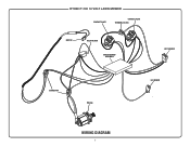
RYOBI P1100 18 VOLT LAWN MOWER CONTACT PLATE CONTACT PLATE TERMINAL BLOCK SWITCH RELAY BLOCK CIRCUIT BOARD ASSEMBLY KEY HOLDER CONNECTOR MOTOR LED BOARD WIRING DIAGRAM 7
RYOBI P1100 18 VOLT LAWN MOWER CONTACT PLATE CONTACT PLATE TERMINAL BLOCK SWITCH RELAY BLOCK CIRCUIT BOARD ASSEMBLY KEY HOLDER CONNECTOR MOTOR LED BOARD WIRING DIAGRAM 7

Parts Diagram 1
Page 4
... 1 Mounting Bracket 1 Starting Instructions Label 1 Screw (M3 x 8 mm,Phillip Pan Hd 3 Lock Nut (M6 3 Handle 1 Rubber Cushion 4 Motor 1 Soft Start Circuit Board 1 Screw (M4 x 16 mm, T20 Torx Socket Pan Hd 8 Key Holder 1 Female Terminal 2 Deck Cover 1 Press Cover (Battery Connect 2 Plate (Battery Connect 2 Base (Battery Connect 2 4 Always mention the model number in all correspondence regarding your LAWN MOWER or when ordering replacement parts. RYOBI P1100 18 VOLT LAWN MOWER The model number will be found...
... 1 Mounting Bracket 1 Starting Instructions Label 1 Screw (M3 x 8 mm,Phillip Pan Hd 3 Lock Nut (M6 3 Handle 1 Rubber Cushion 4 Motor 1 Soft Start Circuit Board 1 Screw (M4 x 16 mm, T20 Torx Socket Pan Hd 8 Key Holder 1 Female Terminal 2 Deck Cover 1 Press Cover (Battery Connect 2 Plate (Battery Connect 2 Base (Battery Connect 2 4 Always mention the model number in all correspondence regarding your LAWN MOWER or when ordering replacement parts. RYOBI P1100 18 VOLT LAWN MOWER The model number will be found...

Parts Diagram 1
Page 5
... 84 661189003 85 639186001 Start Key 1 Battery Cover 1 Torsion Spring (Battery Door 1 Screw (M5 x 0.8 mm, Pan Hd 2 Pressure Spring 1 Spring Pin 2 Latch 2 Quick Lock Press 2 Grass Protector (Right 1 Grass Protector (Left 1 Cut Diameter Label (Left 1 Washer (OD20 x ID13 x 1t 4 Mulching Plug 1 Rear Cover 1 Front Wheel w/Bearing & Cap (6 in ., Inc. Key No. 81)..... 2 Rear Wheel Axle 1 Cotter Pinφ (2.5 8 Washer (OD18 x ID8.4 x 1t 2 Cut Finger Label 1 Wheel Cover 4 Axle Pressure Plate 6 Base (Lock Handle 2 Screw (M4 x 18 mm...
... 84 661189003 85 639186001 Start Key 1 Battery Cover 1 Torsion Spring (Battery Door 1 Screw (M5 x 0.8 mm, Pan Hd 2 Pressure Spring 1 Spring Pin 2 Latch 2 Quick Lock Press 2 Grass Protector (Right 1 Grass Protector (Left 1 Cut Diameter Label (Left 1 Washer (OD20 x ID13 x 1t 4 Mulching Plug 1 Rear Cover 1 Front Wheel w/Bearing & Cap (6 in ., Inc. Key No. 81)..... 2 Rear Wheel Axle 1 Cotter Pinφ (2.5 8 Washer (OD18 x ID8.4 x 1t 2 Cut Finger Label 1 Wheel Cover 4 Axle Pressure Plate 6 Base (Lock Handle 2 Screw (M4 x 18 mm...

Parts Diagram 1
Page 6
Motor 30 86 85 (+) (-) 87 Relay 87a GND M- BATT 1 + BATT 1 SENSE BATT 1 SENSE BATT 2 + COIL RYOBI P1100 18 VOLT LAWN MOWER Switch + - Start Key M+ IN Battery Ground N/A LED LED GND GND MOSI MISO CLK V + LED PCBA Program WIRING DIAGRAM 6
Motor 30 86 85 (+) (-) 87 Relay 87a GND M- BATT 1 + BATT 1 SENSE BATT 1 SENSE BATT 2 + COIL RYOBI P1100 18 VOLT LAWN MOWER Switch + - Start Key M+ IN Battery Ground N/A LED LED GND GND MOSI MISO CLK V + LED PCBA Program WIRING DIAGRAM 6
Parts Diagram 1
Page 7
RYOBI P1100 18 VOLT LAWN MOWER CONTACT PLATE CONTACT PLATE TERMINAL BLOCK SWITCH RELAY BLOCK CIRCUIT BOARD ASSEMBLY KEY HOLDER CONNECTOR MOTOR LED BOARD WIRING DIAGRAM 7
RYOBI P1100 18 VOLT LAWN MOWER CONTACT PLATE CONTACT PLATE TERMINAL BLOCK SWITCH RELAY BLOCK CIRCUIT BOARD ASSEMBLY KEY HOLDER CONNECTOR MOTOR LED BOARD WIRING DIAGRAM 7


