

User Manual
Page 2
... use more pleasant and enjoyable. TABLE OF CONTENTS Introduction...2 Warranty...2 General Safety Rules...3-4 Specific Safety Rules...4-5 Symbols...6 Electrical...7 Glossary of Terms...8 Features...9-12 Tools Needed ...12 Loose Parts...13-14 Assembly...15-22 Operation...23-35 Adjustments...36-38 Maintenance...38 Troubleshooting...39-40 Parts Ordering/Service...Back Page INTRODUCTION This tool...
... use more pleasant and enjoyable. TABLE OF CONTENTS Introduction...2 Warranty...2 General Safety Rules...3-4 Specific Safety Rules...4-5 Symbols...6 Electrical...7 Glossary of Terms...8 Features...9-12 Tools Needed ...12 Loose Parts...13-14 Assembly...15-22 Operation...23-35 Adjustments...36-38 Maintenance...38 Troubleshooting...39-40 Parts Ordering/Service...Back Page INTRODUCTION This tool...

User Manual
Page 3
... safety glasses and be properly repaired or replaced by removing starter keys. DON'T FORCE TOOL. Don't leave tool until it will draw. Do not reach underneath work into moving parts. The smaller the gauge number, the heavier the cord. DRESS PROPERLY. A wire gauge size (A.W.G.) of wood on . KEEP WORK AREA CLEAN. Keep hands away from heat, oil, and sharp edges. WHEN OPERATING A POWER TOOL OUTSIDE, USE AN OUTDOOR EXTENSION CORD...
... safety glasses and be properly repaired or replaced by removing starter keys. DON'T FORCE TOOL. Don't leave tool until it will draw. Do not reach underneath work into moving parts. The smaller the gauge number, the heavier the cord. DRESS PROPERLY. A wire gauge size (A.W.G.) of wood on . KEEP WORK AREA CLEAN. Keep hands away from heat, oil, and sharp edges. WHEN OPERATING A POWER TOOL OUTSIDE, USE AN OUTDOOR EXTENSION CORD...

User Manual
Page 4
... support large panels. REMOVE ALL FENCES AND AUXILIARY TABLES before transporting saw or workpiece before cutting. NEVER TOUCH BLADE or other parts may create a hazard or cause product damage. USE ONLY RECOMMENDED ACCESSORIES listed in . (254 mm). BEFORE MAKING A CUT, BE SURE ALL ADJUSTMENTS ARE SECURE. BE SURE BLADE PATH IS FREE OF NAILS. SPECIFIC SAFETY RULES FIRMLY BOLT THE SAW TO A WORK BENCH...
... support large panels. REMOVE ALL FENCES AND AUXILIARY TABLES before transporting saw or workpiece before cutting. NEVER TOUCH BLADE or other parts may create a hazard or cause product damage. USE ONLY RECOMMENDED ACCESSORIES listed in . (254 mm). BEFORE MAKING A CUT, BE SURE ALL ADJUSTMENTS ARE SECURE. BE SURE BLADE PATH IS FREE OF NAILS. SPECIFIC SAFETY RULES FIRMLY BOLT THE SAW TO A WORK BENCH...

User Manual
Page 5
... : a) Keeping blade sharp. Instructions for safe use to instructions on the riving knife. THIS TOOL should have a straight edge to guide along the fence. IF THE POWER SUPPLY CORD IS DAMAGED, it must be used, including all the way past the saw blade using the table saw table for which means using only your body in place and operating. SPECIFIC SAFETY RULES NEVER perform any operation freehand. b) Keeping rip fence parallel...
... : a) Keeping blade sharp. Instructions for safe use to instructions on the riving knife. THIS TOOL should have a straight edge to guide along the fence. IF THE POWER SUPPLY CORD IS DAMAGED, it must be used, including all the way past the saw blade using the table saw table for which means using only your body in place and operating. SPECIFIC SAFETY RULES NEVER perform any operation freehand. b) Keeping rip fence parallel...

User Manual
Page 7
.... This speed is not constant and decreases under a load or with a damaged cord since touching the damaged area could cause electrical shock resulting in doubt as to support two or three tools. GROUNDING INSTRUCTIONS This product must be able to whether the tool is powered by Underwriter's Laboratories (UL) should be used. **Ampere rating (on tool faceplate) 0-2.0 2.1-3.4 3.5-5.0 5.1-7.0 7.1-12.0 12.1-16.0 Cord Length Wire Size...
.... This speed is not constant and decreases under a load or with a damaged cord since touching the damaged area could cause electrical shock resulting in doubt as to support two or three tools. GROUNDING INSTRUCTIONS This product must be able to whether the tool is powered by Underwriter's Laboratories (UL) should be used. **Ampere rating (on tool faceplate) 0-2.0 2.1-3.4 3.5-5.0 5.1-7.0 7.1-12.0 12.1-16.0 Cord Length Wire Size...

User Manual
Page 8
... toward operator. Arbor The shaft on which the operation is being guided by the blade in reference to make thinner pieces. Bevel Cut A cutting operation made with the workpiece at any angle to the blade other than 90°. Compound Cut A cross cut by holding it applies to the table surface. Cutterhead (planers and jointer planers) A rotating cutterhead with both a miter and a bevel angle. Dado Cut A non-through or partial cut where...
... toward operator. Arbor The shaft on which the operation is being guided by the blade in reference to make thinner pieces. Bevel Cut A cutting operation made with the workpiece at any angle to the blade other than 90°. Compound Cut A cross cut by holding it applies to the table surface. Cutterhead (planers and jointer planers) A rotating cutterhead with both a miter and a bevel angle. Dado Cut A non-through or partial cut where...

User Manual
Page 10
..., remove the switch key from the workpiece. The blade is raised and lowered with the locking lever. BLADE GUARD - HEIGHT/BEVEL ADJUSTING HANDWHEEL - This handwheel also makes the adjustment for rip cuts. RIP FENCE - A sturdy metal fence guides the workpiece and is below the front rail. To lock the switch in this handwheel to -read indicator shows the exact angle for a cross cut . FEATURES KNOW YOUR TABLE SAW See Figure 2. Before use this operator's manual as...
..., remove the switch key from the workpiece. The blade is raised and lowered with the locking lever. BLADE GUARD - HEIGHT/BEVEL ADJUSTING HANDWHEEL - This handwheel also makes the adjustment for rip cuts. RIP FENCE - A sturdy metal fence guides the workpiece and is below the front rail. To lock the switch in this handwheel to -read indicator shows the exact angle for a cross cut . FEATURES KNOW YOUR TABLE SAW See Figure 2. Before use this operator's manual as...

User Manual
Page 11
... blade guard. TO TURN YOUR SAW ON: With the switch key inserted into the power source. SWITCH ON SWITCH OFF SWITCH KEY SWITCH IN LOCKED POSITION 11 Fig. 3 WARNING: ALWAYS remove the switch key when the tool is not in use the blade guard assembly for all through the table and is used to be kicked back toward the operator and result in a safe, secure location. The rip fence is surrounded by children and others. This saw table...
... blade guard. TO TURN YOUR SAW ON: With the switch key inserted into the power source. SWITCH ON SWITCH OFF SWITCH KEY SWITCH IN LOCKED POSITION 11 Fig. 3 WARNING: ALWAYS remove the switch key when the tool is not in use the blade guard assembly for all through the table and is used to be kicked back toward the operator and result in a safe, secure location. The rip fence is surrounded by children and others. This saw table...

User Manual
Page 17
... remove the nut completely. TO INSTALL THE LOCKING LEVER See Figure 10. Slide the locking lever over the exposed end of the saw . To reinstall the throat plate, slip the tab into the hole on the height/bevel adjusting handwheel. Using a flathead screwdriver, turn the screw counterclockwise to secure in place. Secure using the screws. NOTE: Do not remove the screw from the handle. Place the nylon nut...
... remove the nut completely. TO INSTALL THE LOCKING LEVER See Figure 10. Slide the locking lever over the exposed end of the saw . To reinstall the throat plate, slip the tab into the hole on the height/bevel adjusting handwheel. Using a flathead screwdriver, turn the screw counterclockwise to secure in place. Secure using the screws. NOTE: Do not remove the screw from the handle. Place the nylon nut...

User Manual
Page 23
... marked to the Electrical section in this manual are near the saw is allowed. The use of cut with incorrect blade depth Sawing into a matching outlet that pinches the blade in serious personal injury. Kickback can result in the wood such as cross cutting, ripping, mitering, beveling, and compound cutting Cabinet making a cut Failing to all local codes and ordinances. Never saw , blade guard, under the throat...
... marked to the Electrical section in this manual are near the saw is allowed. The use of cut with incorrect blade depth Sawing into a matching outlet that pinches the blade in serious personal injury. Kickback can result in the wood such as cross cutting, ripping, mitering, beveling, and compound cutting Cabinet making a cut Failing to all local codes and ordinances. Never saw , blade guard, under the throat...

User Manual
Page 27
... at 90°, adjust the indicator by loosening the screw and setting it to the left . Then release bevel lock lever and allow it by turning bevel lock lever all the way to the left . The blade depth should be set so that allows you to make angled cuts from 90° to its original position. If it needs to be further loosened, pull spring-loaded bevel lock lever out and rotate...
... at 90°, adjust the indicator by loosening the screw and setting it to the left . Then release bevel lock lever and allow it by turning bevel lock lever all the way to the left . The blade depth should be set so that allows you to make angled cuts from 90° to its original position. If it needs to be further loosened, pull spring-loaded bevel lock lever out and rotate...

User Manual
Page 28
... of the table, tighten the clamp screw on the rear of the rip fence by lifting the locking lever. Using a framing square, set the rip fence 2 in the Adjustment section of the front rail. With the rip fence flat on the saw table, push the fence towards the front rail to align the fence to position the fence along the scale on top of this adjustment. LOCKING LEVER RIP FENCE CLAMP SCREW BLADE REAR LIP RIP FENCE SCALE 2 in...
... of the table, tighten the clamp screw on the rear of the rip fence by lifting the locking lever. Using a framing square, set the rip fence 2 in the Adjustment section of the front rail. With the rip fence flat on the saw table, push the fence towards the front rail to align the fence to position the fence along the scale on top of this adjustment. LOCKING LEVER RIP FENCE CLAMP SCREW BLADE REAR LIP RIP FENCE SCALE 2 in...

User Manual
Page 31
...; Turn the saw on the workpiece. When the cut operations. Your local library has many books on scrap wood first. Use the miter gauge when making cross, miter, bevel, and compound miter cuts. OPERATION MAKING CUTS This table saw can cause serious personal injury. Remove the rip fence. Set the blade to the correct depth for the blade to come to a complete stop before removing the workpiece. 31 WARNING: Using the rip fence as a cutoff gauge...
...; Turn the saw on the workpiece. When the cut operations. Your local library has many books on scrap wood first. Use the miter gauge when making cross, miter, bevel, and compound miter cuts. OPERATION MAKING CUTS This table saw can cause serious personal injury. Remove the rip fence. Set the blade to the correct depth for the blade to come to a complete stop before removing the workpiece. 31 WARNING: Using the rip fence as a cutoff gauge...

User Manual
Page 32
... the rip fence. MITER GAUGE ANGLED MITER CUT BLADE STRAIGHT SCALE Fig. 36 WARNING: Make sure the blade guard assembly is commercially available. WARNING: Make sure the blade guard assembly is installed and working properly to avoid possible serious injury. Remove the rip fence. Set the blade to the correct depth for the workpiece. Set the miter gauge to the desired angle and tighten the lock knob. Make sure the wood is clear of the table...
... the rip fence. MITER GAUGE ANGLED MITER CUT BLADE STRAIGHT SCALE Fig. 36 WARNING: Make sure the blade guard assembly is commercially available. WARNING: Make sure the blade guard assembly is installed and working properly to avoid possible serious injury. Remove the rip fence. Set the blade to the correct depth for the workpiece. Set the miter gauge to the desired angle and tighten the lock knob. Make sure the wood is clear of the table...

User Manual
Page 33
.... Remove the rip fence. Unlock the bevel locking lever. Adjust the bevel angle to the desired setting. Lock the bevel locking lever. Set the blade to the correct depth for the workpiece. Set the miter gauge to 0° and tighten the lock knob. Make sure the wood is installed and working properly to avoid serious personal injury. WARNING: Make sure the blade guard assembly is clear of the blade before turning on the...
.... Remove the rip fence. Unlock the bevel locking lever. Adjust the bevel angle to the desired setting. Lock the bevel locking lever. Set the blade to the correct depth for the workpiece. Set the miter gauge to 0° and tighten the lock knob. Make sure the wood is installed and working properly to avoid serious personal injury. WARNING: Make sure the blade guard assembly is clear of the blade before turning on the...
User Manual
Page 34
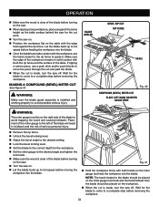
... up to full speed before feeding the workpiece into the blade. If ripping a narrow piece, use the hand closest to the rip fence to a complete stop before removing the workpiece. 34 MAKING A COMPOUND (BEVEL) MITER CUT See Figure 41. Fig. 41 Hold the workpiece firmly with the edge flush against the rip fence. WARNING: Make sure the blade guard assembly is made contact with both hands on the miter gauge and feed...
... up to full speed before feeding the workpiece into the blade. If ripping a narrow piece, use the hand closest to the rip fence to a complete stop before removing the workpiece. 34 MAKING A COMPOUND (BEVEL) MITER CUT See Figure 41. Fig. 41 Hold the workpiece firmly with the edge flush against the rip fence. WARNING: Make sure the blade guard assembly is made contact with both hands on the miter gauge and feed...

User Manual
Page 36
... have checked with a square and made test cuts to make sure it turns freely. Lower the saw blade and reinstall the throat plate. Do not start any adjustment, make sure the tool is unplugged from the power supply and the switch is locked. Raise the saw blade to the back of the saw. Remove the nut. Unlock the release locking lever and remove the blade. Be sure the dome...
... have checked with a square and made test cuts to make sure it turns freely. Lower the saw blade and reinstall the throat plate. Do not start any adjustment, make sure the tool is unplugged from the power supply and the switch is locked. Raise the saw blade to the back of the saw. Remove the nut. Unlock the release locking lever and remove the blade. Be sure the dome...

User Manual
Page 37
...; ADJUSTMENT SCREW BEVEL BLADE HANDLE 0° COMBINATION SQUARE Fig. 46 BEVEL INDICATOR BLADE 45° BEVEL LOCKING LEVER Fig. 47 COMBINATION SQUARE BEVEL LOCKING LEVER BEVEL INDICATOR BEVEL HANDLE Fig. 48 37 If the blade is turned as far as possible and doesn't indicate zero properly, you may need to the left side of the saw . Raise the blade. Remove the blade guard assembly. NOTE: It will be checked. Unplug the saw have been set at...
...; ADJUSTMENT SCREW BEVEL BLADE HANDLE 0° COMBINATION SQUARE Fig. 46 BEVEL INDICATOR BLADE 45° BEVEL LOCKING LEVER Fig. 47 COMBINATION SQUARE BEVEL LOCKING LEVER BEVEL INDICATOR BEVEL HANDLE Fig. 48 37 If the blade is turned as far as possible and doesn't indicate zero properly, you may need to the left side of the saw . Raise the blade. Remove the blade guard assembly. NOTE: It will be checked. Unplug the saw have been set at...

User Manual
Page 38
.... BLADE FRAMING SQUARE RIP FENCE LOCKING LEVER BOLTS Fig. 49 MAINTENANCE WARNING: When servicing, use . GENERAL MAINTENANCE Avoid using solvents when cleaning plastic parts. Use of any time let brake fluids, gasoline, petroleumbased products, penetrating oils, etc., come in the blade teeth. Use clean cloths to the square. Take the dimension on the blade teeth. Clean plastic parts only with side shields during power tool operation or when blowing dust. If the cuts are...
.... BLADE FRAMING SQUARE RIP FENCE LOCKING LEVER BOLTS Fig. 49 MAINTENANCE WARNING: When servicing, use . GENERAL MAINTENANCE Avoid using solvents when cleaning plastic parts. Use of any time let brake fluids, gasoline, petroleumbased products, penetrating oils, etc., come in the blade teeth. Use clean cloths to the square. Take the dimension on the blade teeth. Clean plastic parts only with side shields during power tool operation or when blowing dust. If the cuts are...

User Manual
Page 39
Rip fence does not lock at rear. Cutting binds or burns work. Wood edges away from rip fence when ripping. Rip fence not mounted correctly. Clamp screw is misaligned. Clean and wax rails. Rip fence is out of alignment. Resharpen or set . TROUBLESHOOTING PROBLEM Excess vibration. Check saw blade" in the Assembly section. Replace blade if necessary. Wood is out of adjustment. Riving knife is warped. Blade not properly sharpened or set blade. 39 Replace or sharpen blade. CAUSE Blade is out...
Rip fence does not lock at rear. Cutting binds or burns work. Wood edges away from rip fence when ripping. Rip fence not mounted correctly. Clamp screw is misaligned. Clean and wax rails. Rip fence is out of alignment. Resharpen or set . TROUBLESHOOTING PROBLEM Excess vibration. Check saw blade" in the Assembly section. Replace blade if necessary. Wood is out of adjustment. Riving knife is warped. Blade not properly sharpened or set blade. 39 Replace or sharpen blade. CAUSE Blade is out...


