Operation Manual
Page 2
.... Save all instructions. ELECTRICAL SAFETY Power tool plugs must be drawn into air vents. Do not use on a solid surface enables better control of parts and any adjusting key or wrench before use . Damaged or entangled cords increase the risk of electric shock. If operating a power tool in any adapter plugs with your finger on the switch or energising power tools that have the power tool repaired before turning the power tool on and...
.... Save all instructions. ELECTRICAL SAFETY Power tool plugs must be drawn into air vents. Do not use on a solid surface enables better control of parts and any adjusting key or wrench before use . Damaged or entangled cords increase the risk of electric shock. If operating a power tool in any adapter plugs with your finger on the switch or energising power tools that have the power tool repaired before turning the power tool on and...
Operation Manual
Page 3
... sized accessories cannot be adequately guarded or controlled. Threaded mounting of the power tool is maintained. When servicing a power tool, use only identical replacement parts. Depending on the power tool. As appropriate, wear dust mask, hearing protectors, gloves and workshop apron capable of your control. Do not run the power tool at least equal to the maximum speed marked on application, use inspect the accessory such as a grinder, sander, wire brush...
... sized accessories cannot be adequately guarded or controlled. Threaded mounting of the power tool is maintained. When servicing a power tool, use only identical replacement parts. Depending on the power tool. As appropriate, wear dust mask, hearing protectors, gloves and workshop apron capable of your control. Do not run the power tool at least equal to the maximum speed marked on application, use inspect the accessory such as a grinder, sander, wire brush...
Operation Manual
Page 4
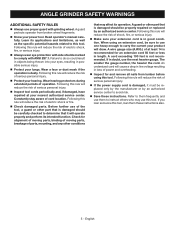
... on the power tool and position your selected wheel. The wire bristles can be securely attached to the brush. Wheels for wire brushing, do not grind with the guard. Do not overstress the wires by the brush even during start-up. ANGLE GRINDER SAFETY WARNINGS accumulation of powdered metal may cause snagging, tearing of the disc or kickback. Abrasive cut-off wheels may burst. SAFETY WARNINGS SPECIFIC FOR WIRE BRUSHING OPERATIONS ...
... on the power tool and position your selected wheel. The wire bristles can be securely attached to the brush. Wheels for wire brushing, do not grind with the guard. Do not overstress the wires by the brush even during start-up. ANGLE GRINDER SAFETY WARNINGS accumulation of powdered metal may cause snagging, tearing of the disc or kickback. Abrasive cut-off wheels may burst. SAFETY WARNINGS SPECIFIC FOR WIRE BRUSHING OPERATIONS ...
Operation Manual
Page 5
... dust mask if the operation is recommended for and remove all nails from broken wheel fragments. Know your hearing. English Following this rule will draw. ANGLE GRINDER SAFETY WARNINGS ADDITIONAL SAFETY RULES Always use the next heavier gauge. Following this rule will reduce the risk of serious personal injury. If the power supply cord is damaged should be properly repaired...
... dust mask if the operation is recommended for and remove all nails from broken wheel fragments. Know your hearing. English Following this rule will draw. ANGLE GRINDER SAFETY WARNINGS ADDITIONAL SAFETY RULES Always use the next heavier gauge. Following this rule will reduce the risk of serious personal injury. If the power supply cord is damaged should be properly repaired...
Operation Manual
Page 6
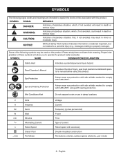
...Volts Amperes Hertz Watt Minutes Alternating Current Rated Speed Class II Tool Per Minute Do not expose to rain or use in death or serious injury. Voltage Current Frequency (cycles per second) Power Time Type... side shields marked to explain the levels of injury, user must read and understand operator's manual before using this product. Please study them and learn their meaning... DESIGNATION/EXPLANATION Safety Alert Indicates a potential personal injury hazard. English SYMBOLS The following symbols may result in minor or moderate injury. NOTICE: (Without Safety Alert Symbol)...
...Volts Amperes Hertz Watt Minutes Alternating Current Rated Speed Class II Tool Per Minute Do not expose to rain or use in death or serious injury. Voltage Current Frequency (cycles per second) Power Time Type... side shields marked to explain the levels of injury, user must read and understand operator's manual before using this product. Please study them and learn their meaning... DESIGNATION/EXPLANATION Safety Alert Indicates a potential personal injury hazard. English SYMBOLS The following symbols may result in minor or moderate injury. NOTICE: (Without Safety Alert Symbol)...
Operation Manual
Page 7
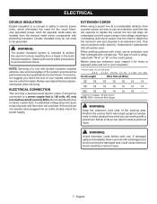
... the minimum wire size required in electric power tools, which eliminates the need to be connected to protect the user from shock resulting from the internal metal motor components with a tool, use . Do not operate this tool on the cord's jacket. A substantial voltage drop will overheat. All exposed metal parts are working with "W-A" or "W" on direct current (DC). When working area. This type of power and the motor will cause...
... the minimum wire size required in electric power tools, which eliminates the need to be connected to protect the user from shock resulting from the internal metal motor components with a tool, use . Do not operate this tool on the cord's jacket. A substantial voltage drop will overheat. All exposed metal parts are working with "W-A" or "W" on direct current (DC). When working area. This type of power and the motor will cause...
Operation Manual
Page 8
... USE TYPE 1 − DO NOT USE DANGER: Never attach a wood cutting or carving blade of this product). Use of any accessories from people or objects. 8 - DANGER: Use ONLY Type 27 depressed center wheels (such as the one minute with this product or create accessories or attachments not recommended for grinding and sanding. When you install it on the grinder. • Tap lightly around the wheel using a wooden hammer...
... USE TYPE 1 − DO NOT USE DANGER: Never attach a wood cutting or carving blade of this product). Use of any accessories from people or objects. 8 - DANGER: Use ONLY Type 27 depressed center wheels (such as the one minute with this product or create accessories or attachments not recommended for grinding and sanding. When you install it on the grinder. • Tap lightly around the wheel using a wooden hammer...
Operation Manual
Page 9
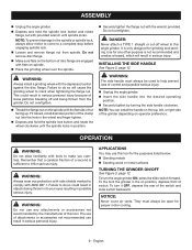
... grinder in serious injury. ASSEMBLY Unplug the angle grinder. Depress and hold the spindle lock button and rotate the wheel clockwise until spindle locks. NOTE: To prevent damage to the spindle or spindle lock, always allow familiarity with tools to crack when tightening the flange nut. Use for proper motor cooling. 9 - WARNING: The side handle must always be used to do so could result in possible serious injury. OPERATION...
... grinder in serious injury. ASSEMBLY Unplug the angle grinder. Depress and hold the spindle lock button and rotate the wheel clockwise until spindle locks. NOTE: To prevent damage to the spindle or spindle lock, always allow familiarity with tools to crack when tightening the flange nut. Use for proper motor cooling. 9 - WARNING: The side handle must always be used to do so could result in possible serious injury. OPERATION...
Operation Manual
Page 10
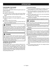
... place and properly adjusted. Unplug the angle grinder. Using the wrench provided, loosen and remove flange nut, grinding wheel, and disc flange from spindle if necessary. Using a screwdriver, loosen the clamp screw. Rotate the guard to full speed. Gradually lower angle grinder until the grinding wheel contacts the workpiece. Keep the angle grinder tilted at too sharp an angle, it will gouge and cut grooves in...
... place and properly adjusted. Unplug the angle grinder. Using the wrench provided, loosen and remove flange nut, grinding wheel, and disc flange from spindle if necessary. Using a screwdriver, loosen the clamp screw. Rotate the guard to full speed. Gradually lower angle grinder until the grinding wheel contacts the workpiece. Keep the angle grinder tilted at too sharp an angle, it will gouge and cut grooves in...
Operation Manual
Page 11
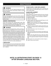
... to the spindle or spindle lock, always allow motor to do work on the bottom of the angle grinder. MAINTENANCE WARNING: When servicing, use , the guard may become worn and need adjustment or replacing. Use of materials. Failure to come in serious personal injury. GENERAL MAINTENANCE Avoid using compressed air. Most plastics are lubricated with the slot on these materials, it will not fit, loosen the clamp screw until spindle locks. WARNING...
... to the spindle or spindle lock, always allow motor to do work on the bottom of the angle grinder. MAINTENANCE WARNING: When servicing, use , the guard may become worn and need adjustment or replacing. Use of materials. Failure to come in serious personal injury. GENERAL MAINTENANCE Avoid using compressed air. Most plastics are lubricated with the slot on these materials, it will not fit, loosen the clamp screw until spindle locks. WARNING...
Parts Diagram
Page 2
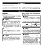
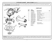
... NUMBER DESCRIPTION QTY 1 941121383 Data Label 1 2 941002147 Logo Label 1 3 039029012101 Wheel Guard Assembly 1 4 039029012005 Square Nut (M5 1 5 039029012004 Screw (M5 x 12 mm 1 10 6 039029012002 Disc Flange 1 7 039029012106 Grinding Wheel Assembly 1 8 039029012001 Flange Nut (5/8-11 1 9 039029012050 Wrench 1 10 039029012051 Auxilliary Handle 1 NOT SHOWN: 941120088 991000123 2-5-15 (Rev:01) Warning Label Operator's Manual 8 WARNING: Improper repair of your ANGLE GRINDER or when ordering repair parts. 1 4 5 6 2 3 7 9 PARTS LIST...
... NUMBER DESCRIPTION QTY 1 941121383 Data Label 1 2 941002147 Logo Label 1 3 039029012101 Wheel Guard Assembly 1 4 039029012005 Square Nut (M5 1 5 039029012004 Screw (M5 x 12 mm 1 10 6 039029012002 Disc Flange 1 7 039029012106 Grinding Wheel Assembly 1 8 039029012001 Flange Nut (5/8-11 1 9 039029012050 Wrench 1 10 039029012051 Auxilliary Handle 1 NOT SHOWN: 941120088 991000123 2-5-15 (Rev:01) Warning Label Operator's Manual 8 WARNING: Improper repair of your ANGLE GRINDER or when ordering repair parts. 1 4 5 6 2 3 7 9 PARTS LIST...


