
Owners Manual
Page 1
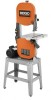
When properly cared for buying a RIDGID product. SAVE THIS MANUAL FOR FUTURE REFERENCE Thank you for , it will give you years of rugged, trouble-free performance. WARNING: To reduce the risk of operation, and operator safety. OPERATOR'S MANUAL 14 in. BAND SAW BS14002 L ON P I U L L P U S OFF H O PUL 10° 0° 15° 30° 4 Your new band saw has been engineered and manufactured to our high standards for dependability, ease of injury, the user must read and understand the operator's manual before using this product.
When properly cared for buying a RIDGID product. SAVE THIS MANUAL FOR FUTURE REFERENCE Thank you for , it will give you years of rugged, trouble-free performance. WARNING: To reduce the risk of operation, and operator safety. OPERATOR'S MANUAL 14 in. BAND SAW BS14002 L ON P I U L L P U S OFF H O PUL 10° 0° 15° 30° 4 Your new band saw has been engineered and manufactured to our high standards for dependability, ease of injury, the user must read and understand the operator's manual before using this product.
Owners Manual
Page 7
... end of the blade. Set The distance that area which will be or has been cut without the workpiece properly supported on the saw table. Freehand (for band saw) Performing a cut by the blade in contact with the workpiece at any angle other than 90°. Kerf The material removed by... the blade in a through cut or the slot produced by the blade. It helps keep the operator's hands well away from wood products. Saw Blade Path...
... end of the blade. Set The distance that area which will be or has been cut without the workpiece properly supported on the saw table. Freehand (for band saw) Performing a cut by the blade in contact with the workpiece at any angle other than 90°. Kerf The material removed by... the blade in a through cut or the slot produced by the blade. It helps keep the operator's hands well away from wood products. Saw Blade Path...
Owners Manual
Page 9
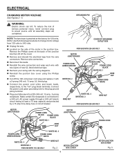
NOTE: The band saw is connected to 240 volts. n Reconnect the leads. n Cut off the cover. n Connect the power cord white and black leads, respectively, to the plug ground ... wire to the "hot" plug blade terminals. n Plug your wiring with a 3-prong 240 volt, 15 amp. n Unplug the saw into a 220-240 volt, 15 amp., 3-prong receptacle. UL listed plug. n Recheck your table saw . Use the following procedures to power source until all assembly steps are completed. n Located on the side of...
NOTE: The band saw is connected to 240 volts. n Reconnect the leads. n Cut off the cover. n Connect the power cord white and black leads, respectively, to the plug ground ... wire to the "hot" plug blade terminals. n Plug your wiring with a 3-prong 240 volt, 15 amp. n Unplug the saw into a 220-240 volt, 15 amp., 3-prong receptacle. UL listed plug. n Recheck your table saw . Use the following procedures to power source until all assembly steps are completed. n Located on the side of...
Owners Manual
Page 11
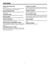
...blade. BLADE GUARD ADJUSTMENT KNOBS Use the blade guide adjustment knobs to clean out sawdust build-up. Use the bevel scale under saw table is perpendicular to keep blade centered on the blade. DUST EXHAUST PORT A 2-1/4 in place. BLADE GUARD Protects the operator... from coming in contact with all operating Features and Safety Rules. FEATURES KNOW YOUR BAND SAW See Figure 6. BLADE GUIDES Blade guides provide full support of the blade and are adjustable for angular cuts. TRACKING KNOB Adjusts tracking ...
...blade. BLADE GUARD ADJUSTMENT KNOBS Use the blade guide adjustment knobs to clean out sawdust build-up. Use the bevel scale under saw table is perpendicular to keep blade centered on the blade. DUST EXHAUST PORT A 2-1/4 in place. BLADE GUARD Protects the operator... from coming in contact with all operating Features and Safety Rules. FEATURES KNOW YOUR BAND SAW See Figure 6. BLADE GUIDES Blade guides provide full support of the blade and are adjustable for angular cuts. TRACKING KNOB Adjusts tracking ...
Owners Manual
Page 13
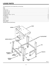
LOOSE PARTS The following items are included with your band saw: Base ...1 Legs...4 Leveling Feet ...4 Hex Nuts (3/8-16) ...8 Leg Brace, Long ...2 Leg Brace, Short ...2 Carriage Bolts, (M8 x 1.25-16) ...40 Flat Washers...40 Lock Washers...40 Hex Nuts (M8)...40 Screws...2 Motor Support ...1 Plate Support ...1 Operator's Manual (Not Shown) SCREWS BASE MOTOR SUPPORT LEG BRACE (SHORT) FLAT WASHERS HEX NUTS LEG BRACE (LONG) LOCK WASHERS CARRIAGE BOLTS HEX NUTS LEVELING FEET 13 PLATE SUPPORT LEG HEX NUTS Fig. 8
LOOSE PARTS The following items are included with your band saw: Base ...1 Legs...4 Leveling Feet ...4 Hex Nuts (3/8-16) ...8 Leg Brace, Long ...2 Leg Brace, Short ...2 Carriage Bolts, (M8 x 1.25-16) ...40 Flat Washers...40 Lock Washers...40 Hex Nuts (M8)...40 Screws...2 Motor Support ...1 Plate Support ...1 Operator's Manual (Not Shown) SCREWS BASE MOTOR SUPPORT LEG BRACE (SHORT) FLAT WASHERS HEX NUTS LEG BRACE (LONG) LOCK WASHERS CARRIAGE BOLTS HEX NUTS LEVELING FEET 13 PLATE SUPPORT LEG HEX NUTS Fig. 8
Owners Manual
Page 14
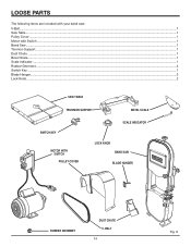
BELT 14 Fig. 9 LOOSE PARTS The following items are included with your band saw: V-Belt...1 Saw Table ...1 Pulley Cover ...1 Motor with Switch ...1 Band Saw ...1 Trunnion Support...1 Dust Chute ...1 Bevel Scale...1 Scale Indicator ...1 Rubber Grommet ...4 Switch Key ...1 Blade Hanger...2 Lock Knob ...2 SAW TABLE TRUNNION SUPPORT BEVEL SCALE SWITCH KEY MOTOR WITH SWITCH ON P I U L L P U OFF S H PULLEY COVER SCALE INDICATOR LOCK KNOB BAND SAW BLADE HANGER PUL L RUBBER GROMMET DUST CHUTE V-
BELT 14 Fig. 9 LOOSE PARTS The following items are included with your band saw: V-Belt...1 Saw Table ...1 Pulley Cover ...1 Motor with Switch ...1 Band Saw ...1 Trunnion Support...1 Dust Chute ...1 Bevel Scale...1 Scale Indicator ...1 Rubber Grommet ...4 Switch Key ...1 Blade Hanger...2 Lock Knob ...2 SAW TABLE TRUNNION SUPPORT BEVEL SCALE SWITCH KEY MOTOR WITH SWITCH ON P I U L L P U OFF S H PULLEY COVER SCALE INDICATOR LOCK KNOB BAND SAW BLADE HANGER PUL L RUBBER GROMMET DUST CHUTE V-
Owners Manual
Page 15
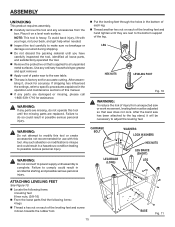
...sections of injury from the box. LEG HEX NUTS LEVELING FOOT Fig. 10 WARNING: To reduce the risk of this tool. After the band saw does not rock. CARRIAGE BOLT WASHERS LOCK WASHERS HEX NUTS LEG BRACE (LONG) LEG BRACE (SHORT) LEG ATTACHING LEVELING FEET See Figure... to do not operate this tool or create accessories not recommended for accurate cutting. Failure to comply could result in a hazardous condition leading to the saw or work surface. n Locate the following items: 4 leveling feet 8 hex nuts, (3/8-16) n From the loose parts find the following items: 4 legs...
...sections of injury from the box. LEG HEX NUTS LEVELING FOOT Fig. 10 WARNING: To reduce the risk of this tool. After the band saw does not rock. CARRIAGE BOLT WASHERS LOCK WASHERS HEX NUTS LEG BRACE (LONG) LEG BRACE (SHORT) LEG ATTACHING LEVELING FEET See Figure... to do not operate this tool or create accessories not recommended for accurate cutting. Failure to comply could result in a hazardous condition leading to the saw or work surface. n Locate the following items: 4 leveling feet 8 hex nuts, (3/8-16) n From the loose parts find the following items: 4 legs...
Owners Manual
Page 16
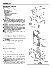
... and washers to your knees bent and lift with holes in the leg stand. Fasten four legs to the underside of a second person, lift the band saw without help. n Fasten two long leg braces and two short leg braces to legs using carriage bolts, washers, lock washers, and nuts, as shown. n... nut. 16 SCREWS BASE MOTOR SUPPORT LEG STAND ASSEMBLY Fig. 12 PUL L HEX BOLTS WASHERS PLATE SUPPORT WASHERS LOCK WASHERS HEX NUTS Fig. 13 MOUNTING BAND SAW TO LEG STAND See Figure 13. n Locate the following hardware: 40 carriage bolts (M8 x 1.25-16) 40 washers (M8) 40 lock washers (M8) 40...
... and washers to your knees bent and lift with holes in the leg stand. Fasten four legs to the underside of a second person, lift the band saw without help. n Fasten two long leg braces and two short leg braces to legs using carriage bolts, washers, lock washers, and nuts, as shown. n... nut. 16 SCREWS BASE MOTOR SUPPORT LEG STAND ASSEMBLY Fig. 12 PUL L HEX BOLTS WASHERS PLATE SUPPORT WASHERS LOCK WASHERS HEX NUTS Fig. 13 MOUNTING BAND SAW TO LEG STAND See Figure 13. n Locate the following hardware: 40 carriage bolts (M8 x 1.25-16) 40 washers (M8) 40 lock washers (M8) 40...
Owners Manual
Page 19
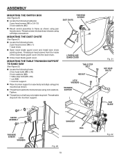
... stop bolt (M8 x 80) 1 nut (M8) 1 trunnion support n Place trunnion support on saw body and align using pins mounted as shown using pan head screws. Tighten. MOUNTING THE TABLE TRUNNION SUPPORT TO BAND SAW See Figure 22. DUST CHUTE PAN HEAD SCREWS LOWER BLADE GUARD COVER TABLE STOP BOLT HEX... PINS LL Fig. 20 19 PU Fig. 21 HEX HEAD BOLTS SAW BLADE Fig. 22 MOUNTING THE DUST CHUTE See Figure 21. Thread screws into band saw chassis using lock washers. n Thread hex head bolts into band saw using a Phillips screwdriver. n Thread hex nut half way onto table stop bolt into ...
... stop bolt (M8 x 80) 1 nut (M8) 1 trunnion support n Place trunnion support on saw body and align using pins mounted as shown using pan head screws. Tighten. MOUNTING THE TABLE TRUNNION SUPPORT TO BAND SAW See Figure 22. DUST CHUTE PAN HEAD SCREWS LOWER BLADE GUARD COVER TABLE STOP BOLT HEX... PINS LL Fig. 20 19 PU Fig. 21 HEX HEAD BOLTS SAW BLADE Fig. 22 MOUNTING THE DUST CHUTE See Figure 21. Thread screws into band saw chassis using lock washers. n Thread hex head bolts into band saw using a Phillips screwdriver. n Thread hex nut half way onto table stop bolt into ...
Owners Manual
Page 23
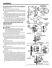
... 0° 15° 30° 4 UPPER BLADE GUIDES L SET SCREW BLADE GUIDE ASSEMBLY WORKPIECE SAW BLADE Fig. 32 BLADE GUIDES SAW BLADE GULLET THUMB SCREWS KNURLED KNOBS 1/64 IN. Never operate the band saw teeth. n Loosen thumb screw and turn knurled knob to the blade. behind the "gullets" of ...thumb. THRUST BEARING BEARING SCREW SAW BLADE THUMB SCREW KNURLED KNOB BEARING SHAFT Fig. 34 23 Make sure blade guides ...
... 0° 15° 30° 4 UPPER BLADE GUIDES L SET SCREW BLADE GUIDE ASSEMBLY WORKPIECE SAW BLADE Fig. 32 BLADE GUIDES SAW BLADE GULLET THUMB SCREWS KNURLED KNOBS 1/64 IN. Never operate the band saw teeth. n Loosen thumb screw and turn knurled knob to the blade. behind the "gullets" of ...thumb. THRUST BEARING BEARING SCREW SAW BLADE THUMB SCREW KNURLED KNOB BEARING SHAFT Fig. 34 23 Make sure blade guides ...
Owners Manual
Page 25
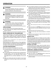
...immediately. REMOVING JAMMED MATERIAL Never remove jammed cutoff pieces until the blade has come to curve in the kerf (cut . This band saw table. Do not restart until the saw from contact with tools to inflict severe injury. Do not force the work into the blade. a 1/8 in the OFF ...circle that can also be cut. For example, a piece of wood and wood composition products BASIC OPERATION OF THE BAND SAW A band saw is longer or wider than the basic saw is sufficient to make you experience excessive vibration or unusual noise, stop . Several relief cuts should be cut is dusty...
...immediately. REMOVING JAMMED MATERIAL Never remove jammed cutoff pieces until the blade has come to curve in the kerf (cut . This band saw table. Do not restart until the saw from contact with tools to inflict severe injury. Do not force the work into the blade. a 1/8 in the OFF ...circle that can also be cut. For example, a piece of wood and wood composition products BASIC OPERATION OF THE BAND SAW A band saw is longer or wider than the basic saw is sufficient to make you experience excessive vibration or unusual noise, stop . Several relief cuts should be cut is dusty...
Owners Manual
Page 28
...loosen the screw holding the guard under the lower wheel. Turn the blade to turn the saw off , remove the switch key, and unplug the saw from your eyes while uncoiling band saw blades. Carefully wipe in the same direction the teeth are pointing in accidental starting causing possible... serious personal injury. UPPER COVER REAR BLADE GUARD SAW BLADE 45° 30° 10° 0° 15...
...loosen the screw holding the guard under the lower wheel. Turn the blade to turn the saw off , remove the switch key, and unplug the saw from your eyes while uncoiling band saw blades. Carefully wipe in the same direction the teeth are pointing in accidental starting causing possible... serious personal injury. UPPER COVER REAR BLADE GUARD SAW BLADE 45° 30° 10° 0° 15...
Owners Manual
Page 29
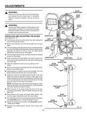
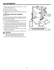
... guide assembly. n Lock blade guide assembly in place by raising or lowering. ADJUSTMENTS n Rotate guard under the saw . n Close upper and lower covers. n Adjust blade guide assembly as described in place before turning on the band saw table back to set approximately 1/8 in. (3 mm) above the workpiece. n Always lock the blade guide assembly...
... guide assembly. n Lock blade guide assembly in place by raising or lowering. ADJUSTMENTS n Rotate guard under the saw . n Close upper and lower covers. n Adjust blade guide assembly as described in place before turning on the band saw table back to set approximately 1/8 in. (3 mm) above the workpiece. n Always lock the blade guide assembly...
Owners Manual
Page 30
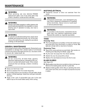
... can no longer be damaged by a qualified service technician. Use clean cloths to be removed with gum and pitch remover. n Keep your band saw blade and close the front cover. MOTOR/ELECTRICAL n Frequently vacuum or blow out sawdust from the inside frequently. Failure to do so could ...slides easily while cutting. BLADE GUIDES See Figure 34. WARNING: Do not, at any way, have it replaced immediately by their use only identical RIDGID replacement parts. WARNING: If the power cord is dusty, also wear a dust mask. n Replace blade guides when filing or grinding has worn ...
... can no longer be damaged by a qualified service technician. Use clean cloths to be removed with gum and pitch remover. n Keep your band saw blade and close the front cover. MOTOR/ELECTRICAL n Frequently vacuum or blow out sawdust from the inside frequently. Failure to do so could ...slides easily while cutting. BLADE GUIDES See Figure 34. WARNING: Do not, at any way, have it replaced immediately by their use only identical RIDGID replacement parts. WARNING: If the power cord is dusty, also wear a dust mask. n Replace blade guides when filing or grinding has worn ...
Owners Manual
Page 33
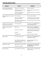
...section, "Mounting the Motor Assembly". Dull blade. Stop feeding, and back up the material slightly, until the band saw vibrates. Replace blade. Blade dulls too quickly. Band saw speeds up. Install proper size fuses or circuit breakers. Starting switch not operating (motor Have switch replaced. Cutting... cutting technique. Cutting incorrect material. Too much tension on motor belt. Fuses or circuit breakers do not have sufficient capacity. Band Saw slows down , trying to reach operating speed. Adjust belt tension, see Assembly section, "Tracking the Blade" section. Kink in...
...section, "Mounting the Motor Assembly". Dull blade. Stop feeding, and back up the material slightly, until the band saw vibrates. Replace blade. Blade dulls too quickly. Band saw speeds up. Install proper size fuses or circuit breakers. Starting switch not operating (motor Have switch replaced. Cutting... cutting technique. Cutting incorrect material. Too much tension on motor belt. Fuses or circuit breakers do not have sufficient capacity. Band Saw slows down , trying to reach operating speed. Adjust belt tension, see Assembly section, "Tracking the Blade" section. Kink in...

Owners Manual
Page 36
Please record the serial number in . BAND SAW BS14002 CUSTOMER SERVICE INFORMATION For parts or service, contact your nearest Ridgid authorized service center. When ordering repair parts, always give the following information: Model No. OPERATOR'S MANUAL 14 in the space provided below. For the location ... you , please call or visit. The model number of the authorized service center nearest you call 1-866-539-1710 or visit us online at www.ridgid.com. Be sure to the motor housing. BS14002 983000-292 7-04 Serial No.
Please record the serial number in . BAND SAW BS14002 CUSTOMER SERVICE INFORMATION For parts or service, contact your nearest Ridgid authorized service center. When ordering repair parts, always give the following information: Model No. OPERATOR'S MANUAL 14 in the space provided below. For the location ... you , please call or visit. The model number of the authorized service center nearest you call 1-866-539-1710 or visit us online at www.ridgid.com. Be sure to the motor housing. BS14002 983000-292 7-04 Serial No.


