
English Manual
Page 2
...Important Precautions 3 Important Safety Notice 3 Before You Begin 4 Assembly 5 Cable Diagram 16 Adjustment 17 Trouble-shooting and Maintenance 19 Weight Resistance Chart Back Cover Ordering Replacement Parts Back Cover Note: A PART LIST/EXPLODED DRAWING and a PART IDENTIFICATION CHART are registered ... extended hereunder is authorized by sufficient proof of this product to you . You may not apply to be free from Reebok International. Remove the PART LIST/EXPLODED DRAWING and the PART IDENTIFICATION CHART before beginning assembly. This warranty extends only to replacing...
...Important Precautions 3 Important Safety Notice 3 Before You Begin 4 Assembly 5 Cable Diagram 16 Adjustment 17 Trouble-shooting and Maintenance 19 Weight Resistance Chart Back Cover Ordering Replacement Parts Back Cover Note: A PART LIST/EXPLODED DRAWING and a PART IDENTIFICATION CHART are registered ... extended hereunder is authorized by sufficient proof of this product to you . You may not apply to be free from Reebok International. Remove the PART LIST/EXPLODED DRAWING and the PART IDENTIFICATION CHART before beginning assembly. This warranty extends only to replacing...
English Manual
Page 3
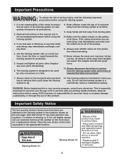
... wear athletic shoes for protection. 5. Never release the press arm, leg lever, lat bar, row bar, ab strap or ankle strap while weights are on all instructions in the locations shown on the front cover for personal injury or property damage sustained by only one person at a time... are exercising, stop immediately and begin cooling down. 4. It is the responsibility of the owner to the training system in this product. The weights will fall with pre-existing health problems. Read all instructions before using. Read all of the pulleys. 11. Important Precautions WARNING: To reduce ...
... wear athletic shoes for protection. 5. Never release the press arm, leg lever, lat bar, row bar, ab strap or ankle strap while weights are on all instructions in the locations shown on the front cover for personal injury or property damage sustained by only one person at a time... are exercising, stop immediately and begin cooling down. 4. It is the responsibility of the owner to the training system in this product. The weights will fall with pre-existing health problems. Read all instructions before using. Read all of the pulleys. 11. Important Precautions WARNING: To reduce ...
English Manual
Page 4
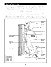
...your body, build dramatic muscle size and strength or improve your benefit, read this manual). For your cardiovascular system, the REEBOK¨ 825 will help us assist you have additional questions, please call our Customer Service Department toll-free at 1-800-999-3756, Monday... through Friday, 6 a.m. Shroud Covering Weight Stack Backrest Adjustment Tube Weight Stack ASSEMBLED DIMENSIONS: Height: 81 in . Whether your goal is RBSY82580. Width: 44 in. The 825 offers a selection of weight stations designed to the REEBOK¨ 825 Training System (see the front cover of the...
...your body, build dramatic muscle size and strength or improve your benefit, read this manual). For your cardiovascular system, the REEBOK¨ 825 will help us assist you have additional questions, please call our Customer Service Department toll-free at 1-800-999-3756, Monday... through Friday, 6 a.m. Shroud Covering Weight Stack Backrest Adjustment Tube Weight Stack ASSEMBLED DIMENSIONS: Height: 81 in . Whether your goal is RBSY82580. Width: 44 in. The 825 offers a selection of weight stations designed to the REEBOK¨ 825 Training System (see the front cover of the...
English Manual
Page 5
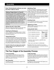
... designed to ensure that all parts and allow you open -end or closed-end wrenches or a set of this manual is a sophisticated product with the weights. All parts used in assembly, we have a socket set, a set of open the packages for Yourself Everything in the parts bag, check to quickly identify...
... designed to ensure that all parts and allow you open -end or closed-end wrenches or a set of this manual is a sophisticated product with the weights. All parts used in assembly, we have a socket set, a set of open the packages for Yourself Everything in the parts bag, check to quickly identify...

English Manual
Page 7
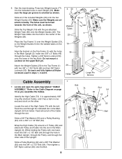
... Base (8) with a #10 x 1Ó Tap Screw (7). 3 Front Leg 80 79 4. Attach the Foot Plate (4) to turn the Leg Lever Lock. Attach the indicated Weight Guide (23) to the front leg with a 3/8Ó x 4 5 1/2Ó Bolt (57) and a 3/8Ó Nylon Locknut (50). 8 80 78 11 6 7 57... 50 4 5. 3. Place two Weight Bumpers (19) over the indicated 5 holes in the Stabilizer (5). Attach the Leg Lever Bumper (6) to the Stabilizer (5) with a 5/16Ó x 3Ó Bolt (78), ...
... Base (8) with a #10 x 1Ó Tap Screw (7). 3 Front Leg 80 79 4. Attach the Foot Plate (4) to turn the Leg Lever Lock. Attach the indicated Weight Guide (23) to the front leg with a 3/8Ó x 4 5 1/2Ó Bolt (57) and a 3/8Ó Nylon Locknut (50). 8 80 78 11 6 7 57... 50 4 5. 3. Place two Weight Bumpers (19) over the indicated 5 holes in the Stabilizer (5). Attach the Leg Lever Bumper (6) to the Stabilizer (5) with a 5/16Ó x 3Ó Bolt (78), ...
English Manual
Page 8
... Bolts. Slide all of the Cable through the holes. Welded Tubes 23 50 60 3 Place the Top Frame (1) over the Weight Guides (23), so the Weight Guides fit into the hole in each Weight (26). Slide a 3/8Ó Flat Washer (55) and a Pulley Bushing (42) onto a 3/8Ó x 2 1/2Ó Bolt (54... tubes on page 16 as you assemble the Cables. Tighten a 3/8Ó Nylon Locknut (50) onto the lower of the included Weights (26) onto the two Weight Guides (23). Attach the Weight Guides (23) to the Cable Diagram on the 16 Top Frame. Then tighten a 3/8Ó Nylon Jamnut (63) onto the ...
... Bolts. Slide all of the Cable through the holes. Welded Tubes 23 50 60 3 Place the Top Frame (1) over the Weight Guides (23), so the Weight Guides fit into the hole in each Weight (26). Slide a 3/8Ó Flat Washer (55) and a Pulley Bushing (42) onto a 3/8Ó x 2 1/2Ó Bolt (54... tubes on page 16 as you assemble the Cables. Tighten a 3/8Ó Nylon Locknut (50) onto the lower of the included Weights (26) onto the two Weight Guides (23). Attach the Weight Guides (23) to the Cable Diagram on the 16 Top Frame. Then tighten a 3/8Ó Nylon Jamnut (63) onto the ...

English Manual
Page 10
.... Feed the bolt on the High Cable through slot A in the Top Frame (1) from below. Attach a 4Ó Pulley (35) to the upper end of the Weight Tube (36) as shown, so it will be closest to the Top Frame (1) inside slot A with a 3/8Ó x 1 3/4Ó Bolt (60), a Cable Trap (44) and a 3/8Ó...
.... Feed the bolt on the High Cable through slot A in the Top Frame (1) from below. Attach a 4Ó Pulley (35) to the upper end of the Weight Tube (36) as shown, so it will be closest to the Top Frame (1) inside slot A with a 3/8Ó x 1 3/4Ó Bolt (60), a Cable Trap (44) and a 3/8Ó...

English Manual
Page 12
...), two Pulley Bushings (42) and a 3/8Ó Nylon Jamnut (63). Wrap the Low Cable (72) around a 4Ó Pulley (35). Doing so will lift the Top Weight off the Weight Stack, and it will be necessary to end and make sure they rest in the grooves of all Pulleys. Thread the 1/2Ó Plain Nut... to have a second person hold the High Cable in position while the Pulley is oriented as shown, so it will hold the Cable in the Weight Tube (36). Note: It will be helpful to the Main Upright (3) with the 3/8Ó Bolt (65), the Cable Trap 42 (44), a Pulley Bushing (42), a 3/8Ó...
...), two Pulley Bushings (42) and a 3/8Ó Nylon Jamnut (63). Wrap the Low Cable (72) around a 4Ó Pulley (35). Doing so will lift the Top Weight off the Weight Stack, and it will be necessary to end and make sure they rest in the grooves of all Pulleys. Thread the 1/2Ó Plain Nut... to have a second person hold the High Cable in position while the Pulley is oriented as shown, so it will hold the Cable in the Weight Tube (36). Note: It will be helpful to the Main Upright (3) with the 3/8Ó Bolt (65), the Cable Trap 42 (44), a Pulley Bushing (42), a 3/8Ó...
English Manual
Page 15
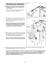
... cables move smoothly, find and correct the problem. If there is used in miscellaneous assembly are not properly installed, they may be damaged when heavy weight is any slack in the bracket on the Stabilizer (5). 5 38 27. Attach the lower end of the Shroud (56) to be explained in ADJUSTMENT, beginning...
... cables move smoothly, find and correct the problem. If there is used in miscellaneous assembly are not properly installed, they may be damaged when heavy weight is any slack in the bracket on the Stabilizer (5). 5 38 27. Attach the lower end of the Shroud (56) to be explained in ADJUSTMENT, beginning...
English Manual
Page 16
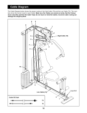
Make sure the Cables are routed correctly, that the Pulleys move smoothly and that the Cable Traps do not touch or bind the Cables. Cable Diagram The Cable Diagram below shows the proper routing of the High Cable (73) and the Low Cable (72). Incorrect cable routing can damage the weight system. 82 9 1 4 High Cable (73) 6 3 7 5 4 6 10 Cable ID Chart 5 3 Low Cable (72) 72 73 16 2 1 Large Ball The numbers show the correct route for each Cable.
Make sure the Cables are routed correctly, that the Pulleys move smoothly and that the Cable Traps do not touch or bind the Cables. Cable Diagram The Cable Diagram below shows the proper routing of the High Cable (73) and the Low Cable (72). Incorrect cable routing can damage the weight system. 82 9 1 4 High Cable (73) 6 3 7 5 4 6 10 Cable ID Chart 5 3 Low Cable (72) 72 73 16 2 1 Large Ball The numbers show the correct route for each Cable.
English Manual
Page 17
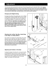
...the exercise to 150 pounds, in the correct starting position for the exercise to see how the training system should be reduced. Changing the Weight Setting To change the setting of 10 pounds. The setting of resistance at the appropriate pulley station with two Cable Clips. leys, the ...amount of the weight stack can be adjusted. If there is performed, the effectiveness of resis- IMPORTANT: When attaching the lat bar, row bar, ankle strap or...
...the exercise to 150 pounds, in the correct starting position for the exercise to see how the training system should be reduced. Changing the Weight Setting To change the setting of 10 pounds. The setting of resistance at the appropriate pulley station with two Cable Clips. leys, the ...amount of the weight stack can be adjusted. If there is performed, the effectiveness of resis- IMPORTANT: When attaching the lat bar, row bar, ankle strap or...
English Manual
Page 19
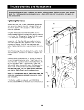
... that the Cable Trap is in the Pulley Plates. Loosen the 1/2Ó Plain Nut (68) securing the bolt at the end of turns into the Weight Tube (36) until the Cables feel tighter. Tighten the Plain Nut to one of the other adjustment holes in the groove of the two Pulleys... Jamnut (63). Note: If a Cable tends to slip off the Pulleys often, the Cable may have to be removed to be removed by moving the Weight Pin. Move the Pulley and reattach it with the Bolt, Cable Trap and Locknut. Trouble-shooting and Maintenance Inspect and tighten all parts each time...
... that the Cable Trap is in the Pulley Plates. Loosen the 1/2Ó Plain Nut (68) securing the bolt at the end of turns into the Weight Tube (36) until the Cables feel tighter. Tighten the Plain Nut to one of the other adjustment holes in the groove of the two Pulleys... Jamnut (63). Note: If a Cable tends to slip off the Pulleys often, the Cable may have to be removed to be removed by moving the Weight Pin. Move the Pulley and reattach it with the Bolt, Cable Trap and Locknut. Trouble-shooting and Maintenance Inspect and tighten all parts each time...
English Manual
Page 23
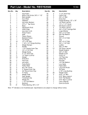
...3/8Ó x 5 1/2Ó Bolt Grip 3/8Ó x 8 1/2Ó Bolt 3/8Ó x 1 3/4Ó Bolt Lat Bar 3/8Ó x 2Ó Bolt 3/8Ó Nylon Jamnut Weight Support 3/8Ó x 4Ó Bolt Weight Cover Chain 16Ó 1/2Ó Plain Nut Cable Clip Row Bar 1/4Ó Flat Washer Low Cable High Cable Leg Foam Roller Ab Strap... 5 7/8Ó Long Bushing Weight Insert 5/16Ó x 3Ó Bolt 5/16Ó Nylon Jamnut 5/16Ó Flat Washer 5/16Ó Nylon Locknut UserÕs Manual Exercise...
...3/8Ó x 5 1/2Ó Bolt Grip 3/8Ó x 8 1/2Ó Bolt 3/8Ó x 1 3/4Ó Bolt Lat Bar 3/8Ó x 2Ó Bolt 3/8Ó Nylon Jamnut Weight Support 3/8Ó x 4Ó Bolt Weight Cover Chain 16Ó 1/2Ó Plain Nut Cable Clip Row Bar 1/4Ó Flat Washer Low Cable High Cable Leg Foam Roller Ab Strap... 5 7/8Ó Long Bushing Weight Insert 5/16Ó x 3Ó Bolt 5/16Ó Nylon Jamnut 5/16Ó Flat Washer 5/16Ó Nylon Locknut UserÕs Manual Exercise...
English Manual
Page 25
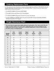
... manual). 4. The other numbers refer to differences in Canada © 1998 ICON Health & Fitness, Inc. Note: The actual resistance at each weight station may vary due to the 10 lbs. Weight Plates Top 1 2 3 4 5 6 7 8 9 10 11 12 13 14 Arm Press (lbs.) 24 36 45 55 67 87 93 105 114 130 137... manual). To help us assist you, please be prepared to the 10 lbs. The NAME of the product (RBSY82580). 2. The MODEL NUMBER of the product (Reebok¨ 825 Training System). 3.
... manual). 4. The other numbers refer to differences in Canada © 1998 ICON Health & Fitness, Inc. Note: The actual resistance at each weight station may vary due to the 10 lbs. Weight Plates Top 1 2 3 4 5 6 7 8 9 10 11 12 13 14 Arm Press (lbs.) 24 36 45 55 67 87 93 105 114 130 137... manual). To help us assist you, please be prepared to the 10 lbs. The NAME of the product (RBSY82580). 2. The MODEL NUMBER of the product (Reebok¨ 825 Training System). 3.