Owners Manual
Page 2
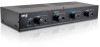
... you connect the AC power source, make sure you have a minimum impedance of amplifiers •Auto transformer impedance protection. 1 The lower the gauge number, the larger the cable (e.g., 12 gauge is larger in different rooms and want to turn them on page 6) PREPARATIONS •Use the PYLE PRO Speaker Selectors only with amplifiers rated at a time, and is designed to operate with a stereo receiver/amplifier that has a maximum of 100 watts per channel...
... you connect the AC power source, make sure you have a minimum impedance of amplifiers •Auto transformer impedance protection. 1 The lower the gauge number, the larger the cable (e.g., 12 gauge is larger in different rooms and want to turn them on page 6) PREPARATIONS •Use the PYLE PRO Speaker Selectors only with amplifiers rated at a time, and is designed to operate with a stereo receiver/amplifier that has a maximum of 100 watts per channel...
Owners Manual
Page 4
... pair of speakers, see " Impedance Chart" on page 4 to selector the best terminals to each set of speakers. Cautions :To avoid damaging your speakers or receiver/amplifier: •Be sure your receiver/amplifier differently to decrease or off. 4.Speader Connections The control center divides the power from your receiver/amplifier's power is especially noticeable when you connect only one pair of terminals. 3 Amplifier A/B Selector Button Press button to select amplifier A and B. 3.Volume Controls Turn the control knob...
... pair of speakers, see " Impedance Chart" on page 4 to selector the best terminals to each set of speakers. Cautions :To avoid damaging your speakers or receiver/amplifier: •Be sure your receiver/amplifier differently to decrease or off. 4.Speader Connections The control center divides the power from your receiver/amplifier's power is especially noticeable when you connect only one pair of terminals. 3 Amplifier A/B Selector Button Press button to select amplifier A and B. 3.Volume Controls Turn the control knob...
Owners Manual
Page 5
5. Amplifier Connections Connect the speaker output of your receiver or amplifier (100watts max.).If you are using a second amplifier, connect it to the B amp terminal. Maximum Amplifier input 100W RMS 150W AVG Maximum Output per Speaker 18W RMS 50W AVG 100W PEAK 4 or 16 OHMS LOAD. 4
5. Amplifier Connections Connect the speaker output of your receiver or amplifier (100watts max.).If you are using a second amplifier, connect it to the B amp terminal. Maximum Amplifier input 100W RMS 150W AVG Maximum Output per Speaker 18W RMS 50W AVG 100W PEAK 4 or 16 OHMS LOAD. 4

Owners Manual
Page 6
... the speakers further than one set of wire. 5 Insert the speakers' positive (+) wires in the nagative terminals. Notes : • If your receiver/amplifier's positive (+) wires into the positive terminals, and negative (-) wires in the positive terminals, and negative (-) wires into the nagative terminals, according to the control center. • For the best results, we recommend 14-gauge, two conductor speaker wire (not supplied) for most connections.
... the speakers further than one set of wire. 5 Insert the speakers' positive (+) wires in the nagative terminals. Notes : • If your receiver/amplifier's positive (+) wires into the positive terminals, and negative (-) wires in the positive terminals, and negative (-) wires into the nagative terminals, according to the control center. • For the best results, we recommend 14-gauge, two conductor speaker wire (not supplied) for most connections.

Owners Manual
Page 7
... time,and on which speakers you turn on. PSPVC4 Speaker Sets On A,B,C or D A+B, A+C, A+D B+C, B+D, C+D A+B+C,A+B+D, A+C+D,B+C+D A+B+C+D Impedance (II) 8 4 3.1 2.4 PSPVC6 Speaker Sets On A,B,C,D,E or F A+B, A+C, A+D, A+E, A+F, B+C, B+D, B+E, B+F, C+D, C+E,C+F, E+F Impedance (IL) 8 4 A+B+C,A+B+D,A+B+E A+B+F,A+C+D,A+C+E A+C+F,A+D+E, A+D+F 3.1 A+E+F, B+C+D, B+C+E B+C+F, B+D+E, B+D+F C+D+E,C+D+F, D+E+F A+B+C+D,A+B+C+E A+B+C+F,A+C+D+E A+C+D+F, A+D+E+F 2.4 B+C+D+E, B+C+D+F C+D+E+F A+B+C+D+E+F 1.7 6 IMPEDANCE CHART Impedance is a measurement of the load placed on your receiver/amplifier...
... time,and on which speakers you turn on. PSPVC4 Speaker Sets On A,B,C or D A+B, A+C, A+D B+C, B+D, C+D A+B+C,A+B+D, A+C+D,B+C+D A+B+C+D Impedance (II) 8 4 3.1 2.4 PSPVC6 Speaker Sets On A,B,C,D,E or F A+B, A+C, A+D, A+E, A+F, B+C, B+D, B+E, B+F, C+D, C+E,C+F, E+F Impedance (IL) 8 4 A+B+C,A+B+D,A+B+E A+B+F,A+C+D,A+C+E A+C+F,A+D+E, A+D+F 3.1 A+E+F, B+C+D, B+C+E B+C+F, B+D+E, B+D+F C+D+E,C+D+F, D+E+F A+B+C+D,A+B+C+E A+B+C+F,A+C+D+E A+C+D+F, A+D+E+F 2.4 B+C+D+E, B+C+D+F C+D+E+F A+B+C+D+E+F 1.7 6 IMPEDANCE CHART Impedance is a measurement of the load placed on your receiver/amplifier...

Owners Manual
Page 8
SPECIFICATIONS Audio Power Handling 50W (R.M.S.)/CH, 100W (Max)/CH Frequency Response 20 Hz to 20KHz Channel Separation 80 dB Crosstalk between channels 50 dB Speaker terminal wire size requirements 14-22 gauge Dimensions (WxHxD) 430x77x160 mm (PSPVC4/PSPVC6) Weight 4.0kgs (8.821bs) (PSPVC4) 5.0kgs (11.02lbs) (PSPVC6) 7
SPECIFICATIONS Audio Power Handling 50W (R.M.S.)/CH, 100W (Max)/CH Frequency Response 20 Hz to 20KHz Channel Separation 80 dB Crosstalk between channels 50 dB Speaker terminal wire size requirements 14-22 gauge Dimensions (WxHxD) 430x77x160 mm (PSPVC4/PSPVC6) Weight 4.0kgs (8.821bs) (PSPVC4) 5.0kgs (11.02lbs) (PSPVC6) 7


