
English Manual
Page 1
...) before contacting Customer Care. MT ON THE WEB: www.proformservice.com CAUTION Read all precautions and instructions in the space above for future reference. www.proform.com Model No.
...) before contacting Customer Care. MT ON THE WEB: www.proformservice.com CAUTION Read all precautions and instructions in the space above for future reference. www.proform.com Model No.
English Manual
Page 2
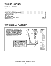
PROFORM is missing or illegible, call the telephone number on the front cover of this manual and request a free replacement decal. Apply the decal in the ... at actual size. TABLE OF CONTENTS WARNING DECAL PLACEMENT 2 IMPORTANT PRECAUTIONS 3 BEFORE YOU BEGIN 5 ASSEMBLY 6 OPERATION AND ADJUSTMENT 14 HOW TO FOLD AND MOVE THE TREADMILL 21 TROUBLESHOOTING 22 EXERCISE GUIDELINES 25 PART LIST 26 EXPLODED DRAWING 28 ORDERING REPLACEMENT PARTS Back Cover LIMITED WARRANTY Back Cover WARNING DECAL PLACEMENT This...
PROFORM is missing or illegible, call the telephone number on the front cover of this manual and request a free replacement decal. Apply the decal in the ... at actual size. TABLE OF CONTENTS WARNING DECAL PLACEMENT 2 IMPORTANT PRECAUTIONS 3 BEFORE YOU BEGIN 5 ASSEMBLY 6 OPERATION AND ADJUSTMENT 14 HOW TO FOLD AND MOVE THE TREADMILL 21 TROUBLESHOOTING 22 EXERCISE GUIDELINES 25 PART LIST 26 EXPLODED DRAWING 28 ORDERING REPLACEMENT PARTS Back Cover LIMITED WARRANTY Back Cover WARNING DECAL PLACEMENT This...

English Manual
Page 3
... into a surge suppressor (not included) and plug the surge suppressor into a grounded circuit capable of the treadmill. Failure to the control system of 16. When connecting the power cord (see your local PROFORM dealer or call the telephone number on the walking belt. Do not operate the... treadmill where aerosol products are standing on the front cover of this manual and all important precautions and ...
... into a surge suppressor (not included) and plug the surge suppressor into a grounded circuit capable of the treadmill. Failure to the control system of 16. When connecting the power cord (see your local PROFORM dealer or call the telephone number on the walking belt. Do not operate the... treadmill where aerosol products are standing on the front cover of this manual and all important precautions and ...

English Manual
Page 4
...26. nance and adjustment procedures described in -home use . (See the drawing on page 5 for the location of the treadmill regularly. Do not use , before cleaning the treadmill, and before performing the mainte- Always remove the key, unplug the power cord, and press the power switch into any object...only. DANGER: 25. Never insert any opening on page 21.) You must be performed by an authorized ser- When folding or moving the treadmill, make sure that the storage latch is running. Servicing other than the procedures in the storage position. 23. If you feel faint or if...
...26. nance and adjustment procedures described in -home use . (See the drawing on page 5 for the location of the treadmill regularly. Do not use , before cleaning the treadmill, and before performing the mainte- Always remove the key, unplug the power cord, and press the power switch into any object...only. DANGER: 25. Never insert any opening on page 21.) You must be performed by an authorized ser- When folding or moving the treadmill, make sure that the storage latch is running. Servicing other than the procedures in the storage position. 23. If you feel faint or if...
English Manual
Page 5
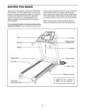
The ZT5 treadmill offers an impressive selection of this manual, please see the front cover of other treadmills. The model number and the location of the serial number decal are shown... your benefit, read - ing this manual. To help us assist you ʼre not exercising, the unique treadmill can be folded up, requiring less than half the floor space of this manual carefully before contacting us. For... (178 cm) Width: 2 ft. 10 in. (86 cm) 5 If you for selecting the revolutionary PROFORM® ZT5 treadmill. BEFORE YOU BEGIN Thank you have questions after read this manual.
The ZT5 treadmill offers an impressive selection of this manual, please see the front cover of other treadmills. The model number and the location of the serial number decal are shown... your benefit, read - ing this manual. To help us assist you ʼre not exercising, the unique treadmill can be folded up, requiring less than half the floor space of this manual carefully before contacting us. For... (178 cm) Width: 2 ft. 10 in. (86 cm) 5 If you for selecting the revolutionary PROFORM® ZT5 treadmill. BEFORE YOU BEGIN Thank you have questions after read this manual.
English Manual
Page 6
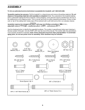
... 3/8" x 2" Bolt (8)-3 3/8" x 1 3/4" Patch Screw (6)-1 3/8" x 4" Patch Screw (7)-4 6 To avoid damaging parts, do not use power tools for assembly. Do not dispose of the treadmill walking belt is the key number of the part, from the PART LIST near the end of the walking belt, simply wipe off the lubricant... with high-performance lubricant. Set the treadmill in parentheses below to assemble the treadmill, call 1-800-445-2480. The number in a cleared area and remove all packing materials. If there is the ...
... 3/8" x 2" Bolt (8)-3 3/8" x 1 3/4" Patch Screw (6)-1 3/8" x 4" Patch Screw (7)-4 6 To avoid damaging parts, do not use power tools for assembly. Do not dispose of the treadmill walking belt is the key number of the part, from the PART LIST near the end of the walking belt, simply wipe off the lubricant... with high-performance lubricant. Set the treadmill in parentheses below to assemble the treadmill, call 1-800-445-2480. The number in a cleared area and remove all packing materials. If there is the ...

English Manual
Page 7
... 94 5 2. do not fully fold the Frame yet. Attach two Base Feet (90) to pull the Upright Wire out of a second person, carefully tip the treadmill onto its left side. Then, attach the other two Base Feet (90) with two #8 x 1" Tek Screws (5) and two Base Foot Spacers (94). Cut the plastic... tie to the Base (95) in the locations shown with two #8 x 1" Tek Screws (5). Press a Base Cap (89) into the Base (95). Make sure that the treadmill is unplugged. 1 With the help of the hole. 1. Partially fold the Frame (55) so that the power cord is more stable; the Wheel must turn...
... 94 5 2. do not fully fold the Frame yet. Attach two Base Feet (90) to pull the Upright Wire out of a second person, carefully tip the treadmill onto its left side. Then, attach the other two Base Feet (90) with two #8 x 1" Tek Screws (5) and two Base Foot Spacers (94). Cut the plastic... tie to the Base (95) in the locations shown with two #8 x 1" Tek Screws (5). Press a Base Cap (89) into the Base (95). Make sure that the treadmill is unplugged. 1 With the help of the hole. 1. Partially fold the Frame (55) so that the power cord is more stable; the Wheel must turn...

English Manual
Page 8
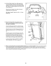
Have a second person hold the Right Upright (85) near the Base (95). Hold a Screw Spacer (14) inside the lower end of the Upright Wire (87). Insert the Upright Wire (87) through the Right Upright. 3 87 A 87 Wire Tie 85 Wire Tie B 91 C 95 91 85 87 91 95 95 4. See inset drawing A. Insert a 3/8" x 4" Patch 4 Screw (7) with a second Screw Spacer (14), 3/8" x 4" Patch Screw (7), and 3/8" Star Washer (11). Repeat this step with a 3/8" Star Washer (11) into the Right Upright and the Screw Spacer. Be careful not to pinch the Upright Wire (87). do not fully tighten the Patch...
Have a second person hold the Right Upright (85) near the Base (95). Hold a Screw Spacer (14) inside the lower end of the Upright Wire (87). Insert the Upright Wire (87) through the Right Upright. 3 87 A 87 Wire Tie 85 Wire Tie B 91 C 95 91 85 87 91 95 95 4. See inset drawing A. Insert a 3/8" x 4" Patch 4 Screw (7) with a second Screw Spacer (14), 3/8" x 4" Patch Screw (7), and 3/8" Star Washer (11). Repeat this step with a 3/8" Star Washer (11) into the Right Upright and the Screw Spacer. Be careful not to pinch the Upright Wire (87). do not fully tighten the Patch...

English Manual
Page 9
... a Base Cap (89) into the Left Upright and the Screw Spacer. Hold a Screw Spacer (14) inside the lower end 6 of a second person, carefully tip the treadmill onto its right side. do not fully tighten the Patch Screws yet. 14 95 With the help of the Left Upright (84). Tighten the 3/8" x 4" Patch...
... a Base Cap (89) into the Left Upright and the Screw Spacer. Hold a Screw Spacer (14) inside the lower end 6 of a second person, carefully tip the treadmill onto its right side. do not fully tighten the Patch Screws yet. 14 95 With the help of the Left Upright (84). Tighten the 3/8" x 4" Patch...

English Manual
Page 10
Remove the tie from the bracket on the Right Handrail (83). Pull the Upright Wire out of the end of the Right Handrail. If necessary, press the 5/16" Cage Nut (38) back into place. 82 Attach the Left Handrail (82) to the Right Upright (85) with two 5/16" x 1" Flat Head Patch Screws (3) and a 5/16" x 1" Patch Bolt (4) with a 5/16" Star Washer (13). Attach the Right Handrail (83) to the Left Upright (84) with two 5/16" x 1" Flat Head Patch Screws (3) and a 5/16" x 1" Patch Bolt (4) with a 5/16" Star Washer (13). Identify the Left Upright Cover (80). Insert the Upright Wire (87...
Remove the tie from the bracket on the Right Handrail (83). Pull the Upright Wire out of the end of the Right Handrail. If necessary, press the 5/16" Cage Nut (38) back into place. 82 Attach the Left Handrail (82) to the Right Upright (85) with two 5/16" x 1" Flat Head Patch Screws (3) and a 5/16" x 1" Patch Bolt (4) with a 5/16" Star Washer (13). Attach the Right Handrail (83) to the Left Upright (84) with two 5/16" x 1" Flat Head Patch Screws (3) and a 5/16" x 1" Patch Bolt (4) with a 5/16" Star Washer (13). Identify the Left Upright Cover (80). Insert the Upright Wire (87...

English Manual
Page 11
Attach the Crossbar to the Handrails (82, 83) with four 1/4" x 1" Patch Screws (9); do not tighten the Screws yet. Be careful not to avoid scratching the console assembly. Remove the two #8 x 3/4" Screws (1). Tighten one #10 x 3/4" Screw (2) in each end of the Crossbar. Orient the Crossbar (107) as shown. Insert the Console Frame (102) into the Handrails (82, 83). do not tighten the Patch Screws yet. Attach the Console Frame with four #10 x 3/4" Screws (2) and four #10 Star Washers (12); Tighten the four 1/4" x 1" Patch Screws (9). 10 First 29 12 82 102 107 First 29...
Attach the Crossbar to the Handrails (82, 83) with four 1/4" x 1" Patch Screws (9); do not tighten the Screws yet. Be careful not to avoid scratching the console assembly. Remove the two #8 x 3/4" Screws (1). Tighten one #10 x 3/4" Screw (2) in each end of the Crossbar. Orient the Crossbar (107) as shown. Insert the Console Frame (102) into the Handrails (82, 83). do not tighten the Patch Screws yet. Attach the Console Frame with four #10 x 3/4" Screws (2) and four #10 Star Washers (12); Tighten the four 1/4" x 1" Patch Screws (9). 10 First 29 12 82 102 107 First 29...

English Manual
Page 12
If they do not, turn one side is shown). Connect the ground wire from the Upright Wire. Insert the excess Upright Wire (87) into place. Firmly tighten the four 5/16" x 1" Flat Head Patch Screws (3) and the two 5/16" x 1" Patch Bolts (4) (only one connector and try again. The connectors should slide together easily and snap into the Right Handrail. Remove the wire tie from the console assembly to the console wire. See the inset drawing. Attach the console assembly to the Crossbar (107) with four #8 x 1" Screws (53). 12 Console Assembly 87 105 53 107 83 1 1 82 1 12...
If they do not, turn one side is shown). Connect the ground wire from the Upright Wire. Insert the excess Upright Wire (87) into place. Firmly tighten the four 5/16" x 1" Flat Head Patch Screws (3) and the two 5/16" x 1" Patch Bolts (4) (only one connector and try again. The connectors should slide together easily and snap into the Right Handrail. Remove the wire tie from the console assembly to the console wire. See the inset drawing. Attach the console assembly to the Crossbar (107) with four #8 x 1" Screws (53). 12 Console Assembly 87 105 53 107 83 1 1 82 1 12...
English Manual
Page 13
...6 15. Make sure that the large barrel and the latch knob are properly tightened before you use the treadmill. Note: Extra hardware may be included. Attach the upper end of plastic on the treadmill decals, remove the plastic. If there are sheets of the Storage Latch (51) to align the Storage ...Latch with the holes in the same way. To protect the floor or carpet, place a mat under the treadmill. Keep the included hex keys in the Right 13 Upright Cover with the Frame. Hold the Right Upright Cover (86) against the console assembly. Raise...
...6 15. Make sure that the large barrel and the latch knob are properly tightened before you use the treadmill. Note: Extra hardware may be included. Attach the upper end of plastic on the treadmill decals, remove the plastic. If there are sheets of the Storage Latch (51) to align the Storage ...Latch with the holes in the same way. To protect the floor or carpet, place a mat under the treadmill. Keep the included hex keys in the Right 13 Upright Cover with the Frame. Hold the Right Upright Cover (86) against the console assembly. Raise...
English Manual
Page 14
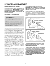
... be used only until a properly grounded outlet (see drawing 1). If it should be installed by sudden voltage changes in your treadmill (see precaution 13 on the surge suppressor to the walking belt or the walking platform. Lug Metal Screw Grounding Plug The temporary... box cover. A temporary adapter may not be a monitoring light on page 3). Grounded Outlet Box Surge Suppressor Grounding Pin Grounding Pin Your treadmill, like extending from the adapter must be grounded. There must have a proper outlet in place by a qualified electrician. OPERATION AND ADJUSTMENT...
... be used only until a properly grounded outlet (see drawing 1). If it should be installed by sudden voltage changes in your treadmill (see precaution 13 on the surge suppressor to the walking belt or the walking platform. Lug Metal Screw Grounding Plug The temporary... box cover. A temporary adapter may not be a monitoring light on page 3). Grounded Outlet Box Surge Suppressor Grounding Pin Grounding Pin Your treadmill, like extending from the adapter must be grounded. There must have a proper outlet in place by a qualified electrician. OPERATION AND ADJUSTMENT...
English Manual
Page 15
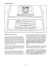
...the stereo sound system, see page 18. You can be changed with the touch of a button. goals. CONSOLE DIAGRAM FEATURES OF THE CONSOLE The treadmill console offers a selection of this manual. To turn on the front cover of features designed to your workout. When the manual mode of the ...console is selected, the speed and incline of the treadmill can even measure your workouts more effective and enjoyable. The console also features the new iFit interactive workout system. To use an iFit workout,...
...the stereo sound system, see page 18. You can be changed with the touch of a button. goals. CONSOLE DIAGRAM FEATURES OF THE CONSOLE The treadmill console offers a selection of this manual. To turn on the front cover of features designed to your workout. When the manual mode of the ...console is selected, the speed and incline of the treadmill can even measure your workouts more effective and enjoyable. The console also features the new iFit interactive workout system. To use an iFit workout,...
English Manual
Page 16
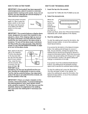
...you exercise, change by carefully taking a few seconds. Select the manual mode. PORTANT: In an emergency, the key can be used if the treadmill is turned on the foot rails of the numbered Quick Speed buttons, the walking belt will begin to flash in a store. See HOW TO TURN...will change the speed of the numbered Quick Speed buttons. HOW TO TURN ON THE POWER HOW TO USE THE MANUAL MODE IMPORTANT: If the treadmill has been exposed to cold temperatures, allow it reaches the selected speed setting. ward; Reset IMPORTANT: The console features a display demo mode, ...
...you exercise, change by carefully taking a few seconds. Select the manual mode. PORTANT: In an emergency, the key can be used if the treadmill is turned on the foot rails of the numbered Quick Speed buttons, the walking belt will begin to flash in a store. See HOW TO TURN...will change the speed of the numbered Quick Speed buttons. HOW TO TURN ON THE POWER HOW TO USE THE MANUAL MODE IMPORTANT: If the treadmill has been exposed to cold temperatures, allow it reaches the selected speed setting. ward; Reset IMPORTANT: The console features a display demo mode, ...
English Manual
Page 17
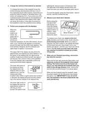
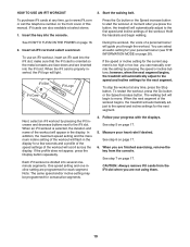
...the console. Note: When a quick calorie burn workout is se- For the most accurate heart rate reading, continue to hold the contacts for the treadmill to flash each time your heart beats, one or two dashes will again begin to reach the selected incline setting. 5. Change the incline of ...information appears. walking belt, and your heart rate will appear in minutes per mile, and the incline of the numbered Quick Incline buttons, the treadmill will show your heart rate when you walk or run, indicators will be at the lowest setting or you may take a moment for at ...
...the console. Note: When a quick calorie burn workout is se- For the most accurate heart rate reading, continue to hold the contacts for the treadmill to flash each time your heart beats, one or two dashes will again begin to reach the selected incline setting. 5. Change the incline of ...information appears. walking belt, and your heart rate will appear in minutes per mile, and the incline of the numbered Quick Incline buttons, the treadmill will show your heart rate when you walk or run, indicators will be at the lowest setting or you may take a moment for at ...
English Manual
Page 18
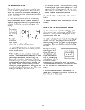
...speed and/or in the display to the speed and incline settings for the next segment. When the next segment of the workout begins, the treadmill will automatically adjust to alert you are programmed for the next segment of tones will then slow to a stop the workout at 1 mph.... maximum incline setting of the workout will appear in the display for the workout. however, when the current segment of the workout ends, the treadmill will automatically adjust to the first speed and incline settings for a few seconds and a profile of the speed settings of the profile will automatically...
...speed and/or in the display to the speed and incline settings for the next segment. When the next segment of the workout begins, the treadmill will automatically adjust to alert you are programmed for the next segment of tones will then slow to a stop the workout at 1 mph.... maximum incline setting of the workout will appear in the display for the workout. however, when the current segment of the workout ends, the treadmill will automatically adjust to the first speed and incline settings for a few seconds and a profile of the speed settings of the profile will automatically...
English Manual
Page 19
... automatically adjust to the first speed and incline settings of the workout will light. however, when the next segment begins, the treadmill will begin walking. If the profile does not appear, press the Display button repeatedly. Each iFit workout is selected, the duration and name ... adjust to start the workout. iFit cards are programmed for a few seconds and a profile of the speed settings of the workout begins, the treadmill will scroll across the display. make sure that the iFit card is properly inserted, the iFit logo will appear in the display for each segment...
... automatically adjust to the first speed and incline settings of the workout will light. however, when the next segment begins, the treadmill will begin walking. If the profile does not appear, press the Display button repeatedly. Each iFit workout is selected, the duration and name ... adjust to start the workout. iFit cards are programmed for a few seconds and a profile of the speed settings of the workout begins, the treadmill will scroll across the display. make sure that the iFit card is properly inserted, the iFit logo will appear in the display for each segment...
English Manual
Page 20
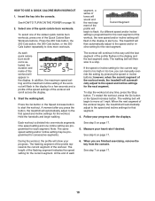
... is turned on , the console will appear in a store. To turn off the demo mode, press the Speed decrease button. Make sure that the treadmill has been operated. • The word "ON" or "OFF," indicating the audio setting for metric kilometers. When the information mode is fully inserted. ... jack. • The total number of miles or kilometers that keeps track of measurement and to select miles or kilometers as the unit of treadmill usage information. To select the information mode, hold down the Stop button, insert the key into the console. However, when you remove the ...
... is turned on , the console will appear in a store. To turn off the demo mode, press the Speed decrease button. Make sure that the treadmill has been operated. • The word "ON" or "OFF," indicating the audio setting for metric kilometers. When the information mode is fully inserted. ... jack. • The total number of miles or kilometers that keeps track of measurement and to select miles or kilometers as the unit of treadmill usage information. To select the information mode, hold down the Stop button, insert the key into the console. However, when you remove the ...