
English Manual
Page 1
... complete customer satisfaction. Write the serial number in this manual before using this manual for future reference. Save this equipment. Visit our website at www.proform.com new products, prizes, fitness tips, and much more! Serial Number Decal (Under Seat) QUESTIONS? PFSY6806.0 Serial No. MST ON THE WEB: www.proformservice.com...
... complete customer satisfaction. Write the serial number in this manual before using this manual for future reference. Save this equipment. Visit our website at www.proform.com new products, prizes, fitness tips, and much more! Serial Number Decal (Under Seat) QUESTIONS? PFSY6806.0 Serial No. MST ON THE WEB: www.proformservice.com...
English Manual
Page 2
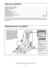
... Note: A PART IDENTIFICATION CHART and a PART LIST/EXPLODED DRAWING are attached in the location shown. Apply the decal in the center of ICON IP, Inc. 2 PROFORM is missing or illegible, call the toll-free telephone number on the weight system. Remove the PART IDENTIFICATION CHART and PART LIST/EXPLODED DRAWING before...
... Note: A PART IDENTIFICATION CHART and a PART LIST/EXPLODED DRAWING are attached in the location shown. Apply the decal in the center of ICON IP, Inc. 2 PROFORM is missing or illegible, call the toll-free telephone number on the weight system. Remove the PART IDENTIFICATION CHART and PART LIST/EXPLODED DRAWING before...
English Manual
Page 3
If the cables bind as described in an elevated position. 14. Do not use only. Place the weight system on the base plate when performing an exercise that all users of the weight system are adequately informed of all cables at any other type weight to add resistance. 6. Use the weight system only with great force. 13. Keep hands and feet away from moisture and dust. Always wear athletic shoes for home use the weight system in this manual. 2. This is especially important for personal injury or property damage sustained by or through the use the weight system. 5. Read all ...
If the cables bind as described in an elevated position. 14. Do not use only. Place the weight system on the base plate when performing an exercise that all users of the weight system are adequately informed of all cables at any other type weight to add resistance. 6. Use the weight system only with great force. 13. Keep hands and feet away from moisture and dust. Always wear athletic shoes for home use the weight system in this manual. 2. This is especially important for personal injury or property damage sustained by or through the use the weight system. 5. Read all ...
English Manual
Page 4
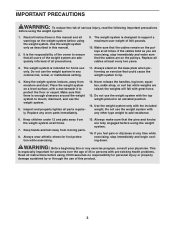
... of this manual carefully before contacting us. model number and serial number before using the weight system. To avoid a registration fee for selecting the versatile PROFORM® FUSION 6.5 LX weight system. For your cardiovascular system, the weight system will help us assist you, please note the product Before reading further, please review the...
... of this manual carefully before contacting us. model number and serial number before using the weight system. To avoid a registration fee for selecting the versatile PROFORM® FUSION 6.5 LX weight system. For your cardiovascular system, the weight system will help us assist you, please note the product Before reading further, please review the...
English Manual
Page 5
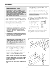
ASSEMBLY Make Things Easier for Yourself Everything in this manual is designed to ensure that there is completed. • Tighten all parts are oriented as you 1 understand the information in a cleared area and remove the packing materials. lowing tools (not included): • Two adjustable wrenches • One rubber mallet • One standard screwdriver • One Phillips screwdriver • Clear tape or masking tape, and soapy water Assembly will go smoothly. For help identifying small parts, use the PART IDENTIFICATION CHART in the location where it . • ...
ASSEMBLY Make Things Easier for Yourself Everything in this manual is designed to ensure that there is completed. • Tighten all parts are oriented as you 1 understand the information in a cleared area and remove the packing materials. lowing tools (not included): • Two adjustable wrenches • One rubber mallet • One standard screwdriver • One Phillips screwdriver • Clear tape or masking tape, and soapy water Assembly will go smoothly. For help identifying small parts, use the PART IDENTIFICATION CHART in the location where it . • ...

English Manual
Page 6
Note: Covering the bolt heads with the four Bolts and four M10 Nylon Locknuts (108). Apply grease to the Base with a piece of tape may 4 come preassembled. the Dip Arm must pivot easily. Attach the Dip Arm (5) to the Dip Arm (5) with the Bolt and an M10 Nylon Locknut (108). Insert the Pin into the Upright 3 (3). 39 Insert four M10 x 55mm Carriage Bolts (83) up through the indicated hole in place. Note: The parts in steps 7, 13, and 14 may help hold 3 them in the Dip Arm. pleted. Do not overtighten the Nylon Locknut; Do not tighten the Nylon Locknuts ...
Note: Covering the bolt heads with the four Bolts and four M10 Nylon Locknuts (108). Apply grease to the Base with a piece of tape may 4 come preassembled. the Dip Arm must pivot easily. Attach the Dip Arm (5) to the Dip Arm (5) with the Bolt and an M10 Nylon Locknut (108). Insert the Pin into the Upright 3 (3). 39 Insert four M10 x 55mm Carriage Bolts (83) up through the indicated hole in place. Note: The parts in steps 7, 13, and 14 may help hold 3 them in the Dip Arm. pleted. Do not overtighten the Nylon Locknut; Do not tighten the Nylon Locknuts ...

English Manual
Page 7
Slide two Weight Bumpers (29) onto the Weight Guides (13). Make sure that the Cable crosses under the Top Frame (12) and hangs between the Weight Guides (13) while this step is centered in the Weight Tube. 5. Do not tighten the Nylon Locknut yet. Tap the Roll Pin (79) into the center hole in the twelfth Weight (27). Do not tighten the Nylon Locknuts. Set the Top Cover (24) over the Top Frame (12). Attach a Weight Guide (13) to the Base (1) with an M10 x 50mm Bolt (96) and an M10 Nylon Locknut (108). Slide eleven Weights (27) onto the Weight Guides. See the inset ...
Slide two Weight Bumpers (29) onto the Weight Guides (13). Make sure that the Cable crosses under the Top Frame (12) and hangs between the Weight Guides (13) while this step is centered in the Weight Tube. 5. Do not tighten the Nylon Locknut yet. Tap the Roll Pin (79) into the center hole in the twelfth Weight (27). Do not tighten the Nylon Locknuts. Set the Top Cover (24) over the Top Frame (12). Attach a Weight Guide (13) to the Base (1) with an M10 x 50mm Bolt (96) and an M10 Nylon Locknut (108). Slide eleven Weights (27) onto the Weight Guides. See the inset ...

English Manual
Page 8
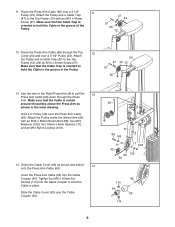
Hold a 4" Pulley (42) over a 3 1/2" 8 Pulley (43). Make sure that the Cable Trap is oriented to the Top Frame (12) with an M10 x 50mm Button Bolt (88), two M10 Washers (105), two 16mm x 6mm Spacers (11), and an M10 Nylon Locknut (108). 7 108 11 105 42 66 26 88 11 105 8. Route the Press Arm Cable (66) between the 3 10 1/2" Pulley (43) and the Cable Trap (47). Attach the Pulley and a Cable Trap (47) to hold the Cable in the groove of the Pulley. 12 66 47 43 97 9. Make sure that the Cable Trap is oriented to 7 ensure correct cable routing during steps 7 through ...
Hold a 4" Pulley (42) over a 3 1/2" 8 Pulley (43). Make sure that the Cable Trap is oriented to the Top Frame (12) with an M10 x 50mm Button Bolt (88), two M10 Washers (105), two 16mm x 6mm Spacers (11), and an M10 Nylon Locknut (108). 7 108 11 105 42 66 26 88 11 105 8. Route the Press Arm Cable (66) between the 3 10 1/2" Pulley (43) and the Cable Trap (47). Attach the Pulley and a Cable Trap (47) to hold the Cable in the groove of the Pulley. 12 66 47 43 97 9. Make sure that the Cable Trap is oriented to 7 ensure correct cable routing during steps 7 through ...
English Manual
Page 9
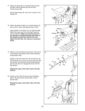
Route the Press Arm Cable (66) through the Press Arm. Use the wire in the Right Press Arm (8) to pull the 13 Press Arm Cable (66) down through the Top 12 Cover (24) and over the Press Arm Cable (66). Tighten four M6 x 10mm Set Screws (114) into the Cable Coupler (64). Make sure that the Cable Trap is oriented to 97 hold the Cable in the groove of the Pulley. 66 13. Attach the Pulley and a Cable Trap (47) to the Top Frame (12) with an M10 x 40mm Screw (97). 24 47 43 12 Make sure that the Cable is oriented to hold the Cable in the inset drawing. Hold a 4" ...
Route the Press Arm Cable (66) through the Press Arm. Use the wire in the Right Press Arm (8) to pull the 13 Press Arm Cable (66) down through the Top 12 Cover (24) and over the Press Arm Cable (66). Tighten four M6 x 10mm Set Screws (114) into the Cable Coupler (64). Make sure that the Cable Trap is oriented to 97 hold the Cable in the groove of the Pulley. 66 13. Attach the Pulley and a Cable Trap (47) to the Top Frame (12) with an M10 x 40mm Screw (97). 24 47 43 12 Make sure that the Cable is oriented to hold the Cable in the inset drawing. Hold a 4" ...

English Manual
Page 10
Slide the Left Shroud (15) under the Top Cover (24). Attach the Left Shroud (15) to the Upright (3) with two M4 x 16mm Self-tapping Screws (99). Attach the Backrest (18) to the Base (1) with 16 two M6 x 115mm Screws (113) and two M6 Washers (107). 18 3 113 107 113 107 10 15. Attach the Right Shroud (14) to the Top Frame (12) with eight M4 x 16mm Self-tapping Screws (99). 15 14 99 99 99 78 77 24 12 99 78 99 15 99 99 99 99 78 99 1 99 77 16. Attach four Storage Hooks to the Left Shroud (15) with two M4 x 10mm Screws (77). Attach the Top Cover and the Left Shroud to...
Slide the Left Shroud (15) under the Top Cover (24). Attach the Left Shroud (15) to the Upright (3) with two M4 x 16mm Self-tapping Screws (99). Attach the Backrest (18) to the Base (1) with 16 two M6 x 115mm Screws (113) and two M6 Washers (107). 18 3 113 107 113 107 10 15. Attach the Right Shroud (14) to the Top Frame (12) with eight M4 x 16mm Self-tapping Screws (99). 15 14 99 99 99 78 77 24 12 99 78 99 15 99 99 99 99 78 99 1 99 77 16. Attach four Storage Hooks to the Left Shroud (15) with two M4 x 10mm Screws (77). Attach the Top Cover and the Left Shroud to...
English Manual
Page 11
Attach a Front and Rear Dip Cap (33, 34) around a Dip Handle (10) with 17 two M6 x 30mm Screws (87) and an M6 x 100mm Screw (85). 19 Set the Seat Frame (4) onto a set of the Dip Arm (5). 19 10 33 51 5 102 35 34 102 20. Repeat this step on the other side of posts on the Front Leg. Do not overtighten the Bolt Set; Attach the Seat (19) to the Seat Frame (4) with two M3 x 32mm Self-tapping Screws (102). Make sure that the barrel of a 2.5" Bolt Set (86). Tighten a Dip Arm Knob (51) into the Dip Handle. Attach an Arm Pad (21) and an Arm Pad Base 20 (22) to the ...
Attach a Front and Rear Dip Cap (33, 34) around a Dip Handle (10) with 17 two M6 x 30mm Screws (87) and an M6 x 100mm Screw (85). 19 Set the Seat Frame (4) onto a set of the Dip Arm (5). 19 10 33 51 5 102 35 34 102 20. Repeat this step on the other side of posts on the Front Leg. Do not overtighten the Bolt Set; Attach the Seat (19) to the Seat Frame (4) with two M3 x 32mm Self-tapping Screws (102). Make sure that the barrel of a 2.5" Bolt Set (86). Tighten a Dip Arm Knob (51) into the Dip Handle. Attach an Arm Pad (21) and an Arm Pad Base 20 (22) to the ...

English Manual
Page 12
Attach the Curl Pad (20) to the Curl Post (9) with 22 two M6 x 30mm Screws (87). 4 23 30 118 23. 21. Then, slide two Pad Covers (30) onto the Leg Pads, and press a 19mm Large Round Cap (118) into the Leg Developer (6). The use of the remaining parts will be explained in the ADJUSTMENTS section, beginning on the following page. 20 9 87 12 Repeat this step for the Seat Frame (4). 21 118 30 23 17 6 22. Make sure that all parts are properly tightened before using the weight system. Next, slide two Leg Pads (23) onto the Pad Tube. Insert a Pad Tube (17) into each Pad Cover....
Attach the Curl Pad (20) to the Curl Post (9) with 22 two M6 x 30mm Screws (87). 4 23 30 118 23. 21. Then, slide two Pad Covers (30) onto the Leg Pads, and press a 19mm Large Round Cap (118) into the Leg Developer (6). The use of the remaining parts will be explained in the ADJUSTMENTS section, beginning on the following page. 20 9 87 12 Repeat this step for the Seat Frame (4). 21 118 30 23 17 6 22. Make sure that all parts are properly tightened before using the weight system. Next, slide two Leg Pads (23) onto the Pad Tube. Insert a Pad Tube (17) into each Pad Cover....

English Manual
Page 13
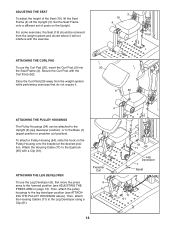
ADJUSTMENTS This section explains how to the raised or lowered position. The weight system can be cleaned with a damp cloth and a mild, non-abrasive detergent. Properly tighten all parts each exercise. Move the Dip Arm to adjust the weight system. Reengage the Dip Pin into the Handle. 5 10 51 ADJUSTING THE PRESS ARM To adjust a Press Arm (7 or 8), first disengage the Press Arm Knob (50). ADJUSTING THE DIP HANDLES The Dip Handles (10) can be moved to three different lengths in the Dip Arm (5), and rotated in the lowered position (see the correct form for important ...
ADJUSTMENTS This section explains how to the raised or lowered position. The weight system can be cleaned with a damp cloth and a mild, non-abrasive detergent. Properly tighten all parts each exercise. Move the Dip Arm to adjust the weight system. Reengage the Dip Pin into the Handle. 5 10 51 ADJUSTING THE PRESS ARM To adjust a Press Arm (7 or 8), first disengage the Press Arm Knob (50). ADJUSTING THE DIP HANDLES The Dip Handles (10) can be moved to three different lengths in the Dip Arm (5), and rotated in the lowered position (see the correct form for important ...
English Manual
Page 14
To attach a Pulley Housing (54), slide the hook on the Upright. Then, attach the Housing Cables (71) to the Eyehook (65) with a Clip (61). For some exercises, the Seat (19) should be removed from the weight system while performing exercises that do not require it will not interfere with the Curl Knob (52). Secure the Curl Post with the exercise. 3 19 4 Post ATTACHING THE CURL PAD To use the Leg Developer (6), first move the press arms to the leg developer position (see ADJUSTING THE PRESS ARM on page 13). Preacher Curl 6 3 61 65 71 54 1 Leg Developer Squat 71 61 14 ...
To attach a Pulley Housing (54), slide the hook on the Upright. Then, attach the Housing Cables (71) to the Eyehook (65) with a Clip (61). For some exercises, the Seat (19) should be removed from the weight system while performing exercises that do not require it will not interfere with the Curl Knob (52). Secure the Curl Post with the exercise. 3 19 4 Post ATTACHING THE CURL PAD To use the Leg Developer (6), first move the press arms to the leg developer position (see ADJUSTING THE PRESS ARM on page 13). Preacher Curl 6 3 61 65 71 54 1 Leg Developer Squat 71 61 14 ...

English Manual
Page 15
ATTACHING THE CURL BAR To use the Curl Bar (58), first attach the curl pad to the Leg Developer with a Clip (61). 58 6 71 61 ATTACHING THE SQUAT BAR To use the Squat Bar (55), first remove the seat (see ADJUSTING THE SEAT on page 14). Finally, attach the Curl Bar to the seat frame (see ATTACHING THE CURL PAD on page 14). Then, attach the Housing Cables (71) to the Housing Cables (71) with two Clips (not shown). Next, attach the Squat Bar to the Leg Developer (6) with four Clips (61) and the two Extension Straps (70). Then attach the pulley housings to a Housing Cable (not ...
ATTACHING THE CURL BAR To use the Curl Bar (58), first attach the curl pad to the Leg Developer with a Clip (61). 58 6 71 61 ATTACHING THE SQUAT BAR To use the Squat Bar (55), first remove the seat (see ADJUSTING THE SEAT on page 14). Finally, attach the Curl Bar to the seat frame (see ATTACHING THE CURL PAD on page 14). Then, attach the Housing Cables (71) to the Housing Cables (71) with two Clips (not shown). Next, attach the Squat Bar to the Leg Developer (6) with four Clips (61) and the two Extension Straps (70). Then attach the pulley housings to a Housing Cable (not ...
English Manual
Page 16
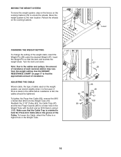
Note: Due to a lower hole in the Weight Tube with the Bolt and an M10 Nylon Locknut (108). Reattach the 3 1/2" Pulley (43), the Cable Trap (47), and the two Finger Guards (48) to the cables and pulleys, the amount of resistance at each exercise station may vary from the Weight Tube (16). To loosen the Cable, attach the Pulley to unlock the wheels. MOVING THE WEIGHT SYSTEM To move the weight system, step on the levers on the Locking Casters (76) to a higher hole in the Weight Tube. 27 28 43 48 16 96 66 48 47 108 16 If there is slack in the cable before resistance is ...
Note: Due to a lower hole in the Weight Tube with the Bolt and an M10 Nylon Locknut (108). Reattach the 3 1/2" Pulley (43), the Cable Trap (47), and the two Finger Guards (48) to the cables and pulleys, the amount of resistance at each exercise station may vary from the Weight Tube (16). To loosen the Cable, attach the Pulley to unlock the wheels. MOVING THE WEIGHT SYSTEM To move the weight system, step on the levers on the Locking Casters (76) to a higher hole in the Weight Tube. 27 28 43 48 16 96 66 48 47 108 16 If there is slack in the cable before resistance is ...

English Manual
Page 17
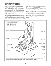
CABLE DIAGRAM The cable diagram shows the proper routing of the Press Arm Cable (66). WEIGHT 1 2 3 4 5 6 7 8 9 10 11 12 Press Arm* 9 15 20 25 30 36 41 46 51 57 62 67 Leg Developer 20 30 42 50 65 73 92 97 108 125 137 144 *The weight resistance shown is for each station may occur. The numbers show the correct route for the 12.5 lb. WEIGHT RESISTANCE CHART The chart below shows the approximate weight resistance for the Cable. Make sure that the Cable and the cable traps have been assembled correctly. Note: The actual resistance at each arm. If the Cable ...
CABLE DIAGRAM The cable diagram shows the proper routing of the Press Arm Cable (66). WEIGHT 1 2 3 4 5 6 7 8 9 10 11 12 Press Arm* 9 15 20 25 30 36 41 46 51 57 62 67 Leg Developer 20 30 42 50 65 73 92 97 108 125 137 144 *The weight resistance shown is for each station may occur. The numbers show the correct route for the 12.5 lb. WEIGHT RESISTANCE CHART The chart below shows the approximate weight resistance for the Cable. Make sure that the Cable and the cable traps have been assembled correctly. Note: The actual resistance at each arm. If the Cable ...
English Manual
Page 18
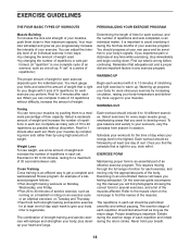
You must gauge your limits and select the amount of strength training and aerobic exercise will adapt and grow as running on a treadmill or riding on an exercise cycle or an elliptical exerciser, on the next page to session. Select a moderate amount of weight and increase the number of repetitions in each set " is a series of repetitions.) The proper amount of weight for you can adjust the intensity level of an individual exercise in any time while exercising, stop immediately and begin cooling down. The combination of weight that you . Find out what is important. ...
You must gauge your limits and select the amount of strength training and aerobic exercise will adapt and grow as running on a treadmill or riding on an exercise cycle or an elliptical exerciser, on the next page to session. Select a moderate amount of weight and increase the number of repetitions in each set " is a series of repetitions.) The proper amount of weight for you can adjust the intensity level of an individual exercise in any time while exercising, stop immediately and begin cooling down. The combination of weight that you . Find out what is important. ...

English Manual
Page 19
Ease into each stretch gradually and go only as far as you can without strain. Stretching at the end of each workout. Brachioradials (forearm) F. Hip Flexors (upper thigh) G. Sartorius (front of calf) L. Soleus (front of thigh) J. STAYING MOTIVATED For motivation, keep a record of sets and repetitions completed. List the date, the exercises performed, the resistance used, and the numbers of each workout is to make exercise a regular and enjoyable part of your weight and key body measurements at the end of every month. Record your everyday life. Remember, the key to ...
Ease into each stretch gradually and go only as far as you can without strain. Stretching at the end of each workout. Brachioradials (forearm) F. Hip Flexors (upper thigh) G. Sartorius (front of calf) L. Soleus (front of thigh) J. STAYING MOTIVATED For motivation, keep a record of sets and repetitions completed. List the date, the exercises performed, the resistance used, and the numbers of each workout is to make exercise a regular and enjoyable part of your weight and key body measurements at the end of every month. Record your everyday life. Remember, the key to ...

English Manual
Page 20
Specifications are subject to change without notice. PFSY6806.0 R0906A Key Qty. No. 63 2 64 2 65 2 66 1 67 8 68 1 69 2 70 2 71 2 72 4 73 1 74 8 75 2 76 2 77 6 78 6 79 1 80 2 81 2 82 1 83 4 84 1 85 1 86 1 87 4 88 2 89 4 90 4 91 2 92 14 93 4 94 2 95 2 96 3 97 4 98 2 99 16 100 3 101 2 102 4 103 4 104 2 105 12 106 2 107 2 108 19 109 2 110 16 111 4 112 1 113 2 114 8 115 1 116 2 117 2 118 4 # - # - # - No. 1 1 2 1 3 1 4 1 5 1 6 1 7 1 8 1 9 1 10 2 11 6 12 1 13 2 14 1 ...
Specifications are subject to change without notice. PFSY6806.0 R0906A Key Qty. No. 63 2 64 2 65 2 66 1 67 8 68 1 69 2 70 2 71 2 72 4 73 1 74 8 75 2 76 2 77 6 78 6 79 1 80 2 81 2 82 1 83 4 84 1 85 1 86 1 87 4 88 2 89 4 90 4 91 2 92 14 93 4 94 2 95 2 96 3 97 4 98 2 99 16 100 3 101 2 102 4 103 4 104 2 105 12 106 2 107 2 108 19 109 2 110 16 111 4 112 1 113 2 114 8 115 1 116 2 117 2 118 4 # - # - # - No. 1 1 2 1 3 1 4 1 5 1 6 1 7 1 8 1 9 1 10 2 11 6 12 1 13 2 14 1 ...