

English Manual
Page 2
... not be shown at actual size. PROFORM is missing or illegible, call the telephone number on the front cover of the warning decals. TABLE OF CONTENTS WARNING DECAL PLACEMENT 2 IMPORTANT PRECAUTIONS 3 BEFORE YOU BEGIN 5 ASSEMBLY 6 OPERATION AND ADJUSTMENT 13 HOW TO FOLD AND MOVE THE TREADMILL 21 TROUBLESHOOTING 22 EXERCISE GUIDELINES 25 PART...
... not be shown at actual size. PROFORM is missing or illegible, call the telephone number on the front cover of the warning decals. TABLE OF CONTENTS WARNING DECAL PLACEMENT 2 IMPORTANT PRECAUTIONS 3 BEFORE YOU BEGIN 5 ASSEMBLY 6 OPERATION AND ADJUSTMENT 13 HOW TO FOLD AND MOVE THE TREADMILL 21 TROUBLESHOOTING 22 EXERCISE GUIDELINES 25 PART...
English Manual
Page 4
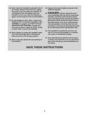
...not use , before cleaning the treadmill, and before performing the mainte- Never leave the treadmill unattended while it is intended for the location of the treadmill regularly. This treadmill is properly assembled. (See ASSEMBLY on page 6, and HOW TO FOLD AND MOVE THE TREADMILL on page 5 for in the ...storage position. 23. 20. Never insert any object into any opening on the treadmill. 24. Inspect and ...
...not use , before cleaning the treadmill, and before performing the mainte- Never leave the treadmill unattended while it is intended for the location of the treadmill regularly. This treadmill is properly assembled. (See ASSEMBLY on page 6, and HOW TO FOLD AND MOVE THE TREADMILL on page 5 for in the ...storage position. 23. 20. Never insert any object into any opening on the treadmill. 24. Inspect and ...
English Manual
Page 6
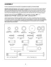
...lubricant. During shipping, some lubricant may be transferred to assemble the treadmill, call 1-800-445-2480. ASSEMBLY To hire an authorized service technician to the top of this manual. Note: The underside of the parts to identify the assembly hardware. To avoid damaging parts, do not use ...power tools for assembly. The number after the parentheses is normal and does not affect treadmill performance. Assembly requires two persons. Note: If a part is not in a ...
...lubricant. During shipping, some lubricant may be transferred to assemble the treadmill, call 1-800-445-2480. ASSEMBLY To hire an authorized service technician to the top of this manual. Note: The underside of the parts to identify the assembly hardware. To avoid damaging parts, do not use ...power tools for assembly. The number after the parentheses is normal and does not affect treadmill performance. Assembly requires two persons. Note: If a part is not in a ...

English Manual
Page 10
... (83) to the Left Upright (84) with two 5/16" x 1" Flat Head Patch Bolts (3) and a 5/16" x 1" Patch Bolt (4) with a 5/16" Star Washer (13). Set the console assembly face down on the Left Handrail. If necessary, press the 5/16" Cage Nuts (38) back into place. 82 Attach the Left Handrail (82) to the...). Slide the Right Upright Cover (86) onto the Right Upright (85). Remove the tie from the bracket on a soft surface to avoid scratching the console assembly. Do not tighten the Patch Bolts yet. 8 87 Bracket 3 83 38 Tie 4 13 86 85 9. Discard the Screws. 9 Console...
... (83) to the Left Upright (84) with two 5/16" x 1" Flat Head Patch Bolts (3) and a 5/16" x 1" Patch Bolt (4) with a 5/16" Star Washer (13). Set the console assembly face down on the Left Handrail. If necessary, press the 5/16" Cage Nuts (38) back into place. 82 Attach the Left Handrail (82) to the...). Slide the Right Upright Cover (86) onto the Right Upright (85). Remove the tie from the bracket on a soft surface to avoid scratching the console assembly. Do not tighten the Patch Bolts yet. 8 87 Bracket 3 83 38 Tie 4 13 86 85 9. Discard the Screws. 9 Console...

English Manual
Page 11
Do not tighten the Screws yet. With the help of a second person, hold the console assembly near the Right Handrail (83) and the Left Handrail (not shown). If they do not, turn one side is shown). Attach the Console Frame with ... 1/4" x 1" Patch Bolts (9). 10 29 12 A 82 102 107 A 29 12 87 83 11. See the inset drawing. Remove the wire tie from the console assembly. 11 Console Assembly Console Wire 87 Wire Tie 4 3 Console Wire 87 Ground Wire 109 83 11 Insert the Console Frame (102) into place. Connect the Upright Wire...
Do not tighten the Screws yet. With the help of a second person, hold the console assembly near the Right Handrail (83) and the Left Handrail (not shown). If they do not, turn one side is shown). Attach the Console Frame with ... 1/4" x 1" Patch Bolts (9). 10 29 12 A 82 102 107 A 29 12 87 83 11. See the inset drawing. Remove the wire tie from the console assembly. 11 Console Assembly Console Wire 87 Wire Tie 4 3 Console Wire 87 Ground Wire 109 83 11 Insert the Console Frame (102) into place. Connect the Upright Wire...

English Manual
Page 12
...If there are properly tightened before tightening any wires. Note: Extra hardware may be included. Set the console assembly on the treadmill decals, remove the plastic. Align the holes in the Right Upright (85). Start all parts are sheets... of the Storage Latch (51) to adjust the walking belt (see HOW TO LOWER THE TREADMILL FOR USE on the Frame (55) with two #8 x 3/4" Screws (1). See steps 4 and 6. Note: It may... (51) so that all six Screws before you use the treadmill. Attach the console assembly to the position shown.
...If there are properly tightened before tightening any wires. Note: Extra hardware may be included. Set the console assembly on the treadmill decals, remove the plastic. Align the holes in the Right Upright (85). Start all parts are sheets... of the Storage Latch (51) to adjust the walking belt (see HOW TO LOWER THE TREADMILL FOR USE on the Frame (55) with two #8 x 3/4" Screws (1). See steps 4 and 6. Note: It may... (51) so that all six Screws before you use the treadmill. Attach the console assembly to the position shown.

English Manual
Page 2
...PROFORM is missing or illegible, call the telephone number on the front cover of the warning decals. Apply the decal in the location shown. Note: The decals may not be shown at actual size. TABLE OF CONTENTS WARNING DECAL PLACEMENT 2 IMPORTANT PRECAUTIONS 3 BEFORE YOU BEGIN 5 PART IDENTIFICATION CHART 6 ASSEMBLY... 7 OPERATION AND ADJUSTMENT 15 HOW TO FOLD AND MOVE THE TREADMILL 24 TROUBLESHOOTING 25 EXERCISE GUIDELINES 28 PART LIST 30 EXPLODED DRAWING 32 ORDERING REPLACEMENT PARTS...
...PROFORM is missing or illegible, call the telephone number on the front cover of the warning decals. Apply the decal in the location shown. Note: The decals may not be shown at actual size. TABLE OF CONTENTS WARNING DECAL PLACEMENT 2 IMPORTANT PRECAUTIONS 3 BEFORE YOU BEGIN 5 PART IDENTIFICATION CHART 6 ASSEMBLY... 7 OPERATION AND ADJUSTMENT 15 HOW TO FOLD AND MOVE THE TREADMILL 24 TROUBLESHOOTING 25 EXERCISE GUIDELINES 28 PART LIST 30 EXPLODED DRAWING 32 ORDERING REPLACEMENT PARTS...

English Manual
Page 4
... in a commercial, rental, or institutional setting. 27. DANGER: 25. This treadmill is properly assembled. (See ASSEMBLY on page 7, and HOW TO FOLD AND MOVE THE TREADMILL on page 5 for home use , before cleaning the treadmill, and before performing the mainte- Do not use this treadmill in this manual should be able to safely lift 45 lbs...
... in a commercial, rental, or institutional setting. 27. DANGER: 25. This treadmill is properly assembled. (See ASSEMBLY on page 7, and HOW TO FOLD AND MOVE THE TREADMILL on page 5 for home use , before cleaning the treadmill, and before performing the mainte- Do not use this treadmill in this manual should be able to safely lift 45 lbs...

English Manual
Page 6
The number following the key number is the quantity used for assembly. The number in the hardware kit, check to identify small parts used for assembly. Note: If a part is not in parentheses below to see if it is the key number of the part, from the PART LIST near the ...
The number following the key number is the quantity used for assembly. The number in the hardware kit, check to identify small parts used for assembly. Note: If a part is not in parentheses below to see if it is the key number of the part, from the PART LIST near the ...

English Manual
Page 7
... to the Base (94) with a soft cloth and a mild, non-abrasive cleaner. •• To identify small parts, see page 6. •• Assembly requires the following tools: the included hex keys one adjustable wrench one Phillips screwdriver scissors To avoid damaging parts, do not use power tools for... assembly. 1. Do not dispose of the packing materials until you nish assembly. •• The underside of the walking belt is lubricant on top of the walking belt or...
... to the Base (94) with a soft cloth and a mild, non-abrasive cleaner. •• To identify small parts, see page 6. •• Assembly requires the following tools: the included hex keys one adjustable wrench one Phillips screwdriver scissors To avoid damaging parts, do not use power tools for... assembly. 1. Do not dispose of the packing materials until you nish assembly. •• The underside of the walking belt is lubricant on top of the walking belt or...

English Manual
Page 10
Set the console assembly face down on a soft 8 surface to the Left Upright 7 (89) with two #10 x 3/4" Flat Head Screws (112), two #10 x 3/4" Screws (9), and two 1/4" Star Washers (35) ... x 3/4" Screws (9) or the #10 x 3/4" Flat Head Screws (112). Remove the two indicated Screws (A). Discard the two Screws. Orient the Crossbar (93) as shown. 7. A 93 Console Assembly 9. Attach the Left Handrail (88) to avoid scratching the console assem- Do not fully tighten the Screws and Bolt yet. 87 Attach the Right Handrail...
Set the console assembly face down on a soft 8 surface to the Left Upright 7 (89) with two #10 x 3/4" Flat Head Screws (112), two #10 x 3/4" Screws (9), and two 1/4" Star Washers (35) ... x 3/4" Screws (9) or the #10 x 3/4" Flat Head Screws (112). Remove the two indicated Screws (A). Discard the two Screws. Orient the Crossbar (93) as shown. 7. A 93 Console Assembly 9. Attach the Left Handrail (88) to avoid scratching the console assem- Do not fully tighten the Screws and Bolt yet. 87 Attach the Right Handrail...

English Manual
Page 11
...See the inset drawing. Start all ten Screws, 35 87 and then tighten each of a second person, hold the con- 10 sole assembly near the Left Handrail (88). With the help of them. 113 See step 7. The connectors should slide together easily and snap into the... Left Handrail. Console Wire 81 Console Assembly Console Wire 81 88 Wire Tie 11. Attach the console assembly with six #8 x 1/2" Screws (1), four 1/4" x 1/2" Screws (36), four 5/16" Flat Washers (113), and four 1/4" Star Washers ...
...See the inset drawing. Start all ten Screws, 35 87 and then tighten each of a second person, hold the con- 10 sole assembly near the Left Handrail (88). With the help of them. 113 See step 7. The connectors should slide together easily and snap into the... Left Handrail. Console Wire 81 Console Assembly Console Wire 81 88 Wire Tie 11. Attach the console assembly with six #8 x 1/2" Screws (1), four 1/4" x 1/2" Screws (36), four 5/16" Flat Washers (113), and four 1/4" Star Washers ...

English Manual
Page 12
... (85) onto the Left 13 Handrail (88). Align the holes in the Left 14 Upright Cover with the holes in the same way. 80 1 Console Assembly 79 1 1 89 90 12 Slide the Right Handrail Cover (86) onto the Right Handrail (87). Attach the Left Upright Cover with two #8 x 1/2" Screws (1). 85 88.... Firmly tighten the four the 3/8" x 2 3/4" Screws (7) and the four 3/8" x 1 1/4" Screws (8) (only 12 one side is shown). Hold the Left Upright Cover (79) against the console assembly. 12. Attach the Handrail Covers with three #8 x 1/2" Screws (1).
... (85) onto the Left 13 Handrail (88). Align the holes in the Left 14 Upright Cover with the holes in the same way. 80 1 Console Assembly 79 1 1 89 90 12 Slide the Right Handrail Cover (86) onto the Right Handrail (87). Attach the Left Upright Cover with two #8 x 1/2" Screws (1). 85 88.... Firmly tighten the four the 3/8" x 2 3/4" Screws (7) and the four 3/8" x 1 1/4" Screws (8) (only 12 one side is shown). Hold the Left Upright Cover (79) against the console assembly. 12. Attach the Handrail Covers with three #8 x 1/2" Screws (1).

English Manual
Page 13
Next, see page 26 and follow all instructions in the power cord. IMPORTANT: Make sure to the console assembly with four #8 x 1/2" Screws (1). 108 107 1 Console 1 Assembly 1 16. When the frame stops moving , remove the key from the console and unplug the power cord. Then, see page 17 ...and turn on 16 the power. 15. Attach the Left Tray (107) and the Right Tray 15 (108) to follow the instructions under “"The incline of the treadmill...
Next, see page 26 and follow all instructions in the power cord. IMPORTANT: Make sure to the console assembly with four #8 x 1/2" Screws (1). 108 107 1 Console 1 Assembly 1 16. When the frame stops moving , remove the key from the console and unplug the power cord. Then, see page 17 ...and turn on 16 the power. 15. Attach the Left Tray (107) and the Right Tray 15 (108) to follow the instructions under “"The incline of the treadmill...


