

English Manual
Page 3
...It is intended only as described in this manual. 4. Inspect and properly tighten all times. 9. Always unplug the power cord when the elliptical is intended for low-power devices such as cell phone chargers, into a grounded circuit. the pedals will continue to an improper receptacle. IMPORTANT...or injury to persons, read all important precautions and instructions in this manual and all warnings on each side. sentative only. 14. The elliptical should be used by an authorized service repre- SAVE THESE INSTRUCTIONS 3 Before beginning any worn parts immediately. 8. The...
...It is intended only as described in this manual. 4. Inspect and properly tighten all times. 9. Always unplug the power cord when the elliptical is intended for low-power devices such as cell phone chargers, into a grounded circuit. the pedals will continue to an improper receptacle. IMPORTANT...or injury to persons, read all important precautions and instructions in this manual and all warnings on each side. sentative only. 14. The elliptical should be used by an authorized service repre- SAVE THESE INSTRUCTIONS 3 Before beginning any worn parts immediately. 8. The...
English Manual
Page 4
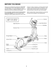
... the front cover of this Before reading further, please familiarize yourself with the parts that are shown on the front cover of this manual. The 14.0 RE elliptical provides an impressive selection of features designed to make your benefit, read this manual carefully before contacting us assist you, note the product model...
... the front cover of this Before reading further, please familiarize yourself with the parts that are shown on the front cover of this manual. The 14.0 RE elliptical provides an impressive selection of features designed to make your benefit, read this manual carefully before contacting us assist you, note the product model...

English Manual
Page 5
... Split Washer (131)–-8 M8 x 25mm x 1.5mm Washer (126)–-4 M17 x 27mm Wave Washer (88)–-4 M8 Locknut (105)–-6 M4 x 16mm Screw (93)–-14 M6 x 12mm Screw (139)–-8 M6 x 50mm Screw (62)–-2 M8 x 16mm Screw (102)–-12 M8 x 25mm Screw (128)–-2 M8 x 45mm Bolt (104...
... Split Washer (131)–-8 M8 x 25mm x 1.5mm Washer (126)–-4 M17 x 27mm Wave Washer (88)–-4 M8 Locknut (105)–-6 M4 x 16mm Screw (93)–-14 M6 x 12mm Screw (139)–-8 M6 x 50mm Screw (62)–-2 M8 x 16mm Screw (102)–-12 M8 x 25mm Screw (128)–-2 M8 x 45mm Bolt (104...
English Manual
Page 9
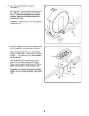
.... 6 With the help of a second person, place some of the Frame (1). 41 7. Identify the Right Pedal (14) and the Right Pedal Arm (12) assembly and orient them as shown. 7 Attach the Right Pedal (14) to prevent it from tipping while you complete this step. 1 Tighten the Leveling Foot (41) into the... Right Pedal Arm (12) and the Right Pedal (14). 6. Have the second person hold the Frame to the Right Pedal Arm (12) with an M6 x 13mm Washer (140) into the underside of the packaging...
.... 6 With the help of a second person, place some of the Frame (1). 41 7. Identify the Right Pedal (14) and the Right Pedal Arm (12) assembly and orient them as shown. 7 Attach the Right Pedal (14) to prevent it from tipping while you complete this step. 1 Tighten the Leveling Foot (41) into the... Right Pedal Arm (12) and the Right Pedal (14). 6. Have the second person hold the Frame to the Right Pedal Arm (12) with an M6 x 13mm Washer (140) into the underside of the packaging...
English Manual
Page 12
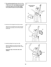
... of the Rear Upright Cover gently into the Rear Upright Cover (24). 25 5 24 14. Tip: It may be necessary to bend the upper end of the elliptical. 12 32 8 30 93 Identify the Right Front Leg Cover (30). 14 Attach the Right Front Leg Cover (30) to the Upright (5) with two M4...
... of the Rear Upright Cover gently into the Rear Upright Cover (24). 25 5 24 14. Tip: It may be necessary to bend the upper end of the elliptical. 12 32 8 30 93 Identify the Right Front Leg Cover (30). 14 Attach the Right Front Leg Cover (30) to the Upright (5) with two M4...
English Manual
Page 14
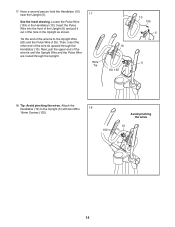
.... Next, pull the upper end of the wire tie to the Upright (5) with two M8 x 18 16mm Screws (102). 102 Avoid pinching the wires 10 5 14 Have a second person hold the Handlebar (10) near the Upright (5). Locate the Pulse Wire (135) in the Upright as shown. See the inset drawing. 17...
.... Next, pull the upper end of the wire tie to the Upright (5) with two M8 x 18 16mm Screws (102). 102 Avoid pinching the wires 10 5 14 Have a second person hold the Handlebar (10) near the Upright (5). Locate the Pulse Wire (135) in the Upright as shown. See the inset drawing. 17...
English Manual
Page 34
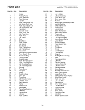
... Axle Ground Screw M6 Washer Pivot Screw Pedal Arm Cap Idler Bolt M10 x 120mm Screw 34 PFEL18012.0 R1012A Key No. Qty. 1 1 2 1 3 1 4 1 5 1 6 1 7 1 8 1 9 1 10 1 11 1 12 1 13 1 14 1 15 1 16 2 17 2 18 1 19 1 20 1 21 1 22 1 23 1 24 1 25 1 26 1 27 1 28 1 29 1 30 1 31 1 32 1 33 1 34 2 35 2 36 2 37 4 38 1 39...
... Axle Ground Screw M6 Washer Pivot Screw Pedal Arm Cap Idler Bolt M10 x 120mm Screw 34 PFEL18012.0 R1012A Key No. Qty. 1 1 2 1 3 1 4 1 5 1 6 1 7 1 8 1 9 1 10 1 11 1 12 1 13 1 14 1 15 1 16 2 17 2 18 1 19 1 20 1 21 1 22 1 23 1 24 1 25 1 26 1 27 1 28 1 29 1 30 1 31 1 32 1 33 1 34 2 35 2 36 2 37 4 38 1 39...
English Manual
Page 35
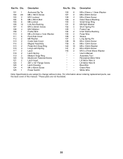
... without notice. Description 101 1 102 20 103 2 104 6 105 6 106 12 107 4 108 4 109 1 110 2 111 6 112 2 113 2 114 2 115 2 116 4 117 2 118 2 119 2 120 14 121 2 122 1 123 2 124 4 125 1 Anchored Zip Tie M8 x 16mm Screw M10 Locknut M8 x 45mm Bolt M8 Locknut Link Arm Bushing M10 x 25mm Screw M10...
... without notice. Description 101 1 102 20 103 2 104 6 105 6 106 12 107 4 108 4 109 1 110 2 111 6 112 2 113 2 114 2 115 2 116 4 117 2 118 2 119 2 120 14 121 2 122 1 123 2 124 4 125 1 Anchored Zip Tie M8 x 16mm Screw M10 Locknut M8 x 45mm Bolt M8 Locknut Link Arm Bushing M10 x 25mm Screw M10...

English Manual
Page 39
39 128 111 126 91 102 106 115 114 13 138 132 117 121 140 116 139 118 123 137 138 127 113 129 112 136 134 106 106 88 15 106 94 98 140 92 130 126 128 111 111 126 94 106 62 139 14 12 114 139 140 140 139 130 92 106 98 88 90 115 106 140 111 62 106 126 102 106 111 126 128 116 134 138 132 117 118 121 123 137 138 136 129 113 112 127 Model No. PFEL18012.0 R1012A EXPLODED DRAWING D
39 128 111 126 91 102 106 115 114 13 138 132 117 121 140 116 139 118 123 137 138 127 113 129 112 136 134 106 106 88 15 106 94 98 140 92 130 126 128 111 111 126 94 106 62 139 14 12 114 139 140 140 139 130 92 106 98 88 90 115 106 140 111 62 106 126 102 106 111 126 128 116 134 138 132 117 118 121 123 137 138 136 129 113 112 127 Model No. PFEL18012.0 R1012A EXPLODED DRAWING D
