

User Manual
Page 1
Always Wear Eye Protection During Operation 181347 Rev. 1 3.21.02 RD Printed in serious injury. Failure to do so can result in U.S.A. IMPORTANT MANUAL Do Not Throw Away 02478 OWNER'S MANUAL MODEL: PR1842STA LAWN TRACTOR WARNING: Read this Owner's Manual and follow all Warnings and Safety Instructions.
Always Wear Eye Protection During Operation 181347 Rev. 1 3.21.02 RD Printed in serious injury. Failure to do so can result in U.S.A. IMPORTANT MANUAL Do Not Throw Away 02478 OWNER'S MANUAL MODEL: PR1842STA LAWN TRACTOR WARNING: Read this Owner's Manual and follow all Warnings and Safety Instructions.

User Manual
Page 4
... observe the safety rules. • Follow a regular schedule in effective working order by the operator. Should you to service or repair this manual). 4 CCA: 230 CASE SIZE: U1R BLADE BOLT TORQUE: 27-35 FT. It has been designed, engineered and manufactured to give you ...cannot easily remedy, please contact your tractor. • Follow the instructions under "Customer Responsibili- Please read and retain this owner's manual. WARNING: This tractor is used, it should not be maintained in maintaining, caring for the muffler is equipped with an internal combustion...
... observe the safety rules. • Follow a regular schedule in effective working order by the operator. Should you to service or repair this manual). 4 CCA: 230 CASE SIZE: U1R BLADE BOLT TORQUE: 27-35 FT. It has been designed, engineered and manufactured to give you ...cannot easily remedy, please contact your tractor. • Follow the instructions under "Customer Responsibili- Please read and retain this owner's manual. WARNING: This tractor is used, it should not be maintained in maintaining, caring for the muffler is equipped with an internal combustion...

User Manual
Page 6
...assembly easier. Tighten securely. SEAT PAN LABEL TERMINAL TERMINAL FIG. 2 6 Standard wrench sizes are in CUSTOMER RESPONSIBILITIES section of this manual for any additional loose parts or cartons and remove. TO REMOVE TRACTOR FROM CARTON UNPACK CARTON • Remove all accessible loose parts...in the operating position (seated behind the steering wheel). ing holes in dash and push down to raised position. • If this manual, it means when you assemble must be tightened securely. INSTALL STEERING WHEEL • Position front wheels of steering wheel. • ...
...assembly easier. Tighten securely. SEAT PAN LABEL TERMINAL TERMINAL FIG. 2 6 Standard wrench sizes are in CUSTOMER RESPONSIBILITIES section of this manual for any additional loose parts or cartons and remove. TO REMOVE TRACTOR FROM CARTON UNPACK CARTON • Remove all accessible loose parts...in the operating position (seated behind the steering wheel). ing holes in dash and push down to raised position. • If this manual, it means when you assemble must be tightened securely. INSTALL STEERING WHEEL • Position front wheels of steering wheel. • ...

User Manual
Page 7
.... • Start the engine. SEAT SEAT PAN SHOULDER BOLT FLAT WASHER TO ROLL TRACTOR OFF SKID (See Operation section, page 10, for assembly of this manual. Move gearshift lever to 1st gear. • Slowly release clutch/brake pedal and slowly drive tractor off skid. • Apply brake to stop tractor, set...
.... • Start the engine. SEAT SEAT PAN SHOULDER BOLT FLAT WASHER TO ROLL TRACTOR OFF SKID (See Operation section, page 10, for assembly of this manual. Move gearshift lever to 1st gear. • Slowly release clutch/brake pedal and slowly drive tractor off skid. • Apply brake to stop tractor, set...

User Manual
Page 8
... at proper level. ✓ Fuel tank is properly adjusted. See "TO ADJUST BRAKE" in the Service and Adjustments section of this manual. THE MULCHER PLATE MUST ONLY BE USED WITH THE MULCHING BLADES THAT CAME PACKED SEPARATELY IN THE CARTON. See that the brake is filled... hour at 6 amps). ✓ Seat is adjusted comfortably and tightened securely. ✓ All tires are shown for discharging or installation of this manual. CHECK BRAKE SYSTEM After you start the engine. ✓ Be sure brake system is now ready for replacing motion and mower blade drive belts in...
... at proper level. ✓ Fuel tank is properly adjusted. See "TO ADJUST BRAKE" in the Service and Adjustments section of this manual. THE MULCHER PLATE MUST ONLY BE USED WITH THE MULCHING BLADES THAT CAME PACKED SEPARATELY IN THE CARTON. See that the brake is filled... hour at 6 amps). ✓ Seat is adjusted comfortably and tightened securely. ✓ All tires are shown for discharging or installation of this manual. CHECK BRAKE SYSTEM After you start the engine. ✓ Be sure brake system is now ready for replacing motion and mower blade drive belts in...

User Manual
Page 10
... to your tractor. LIGHT SWITCH POSITION: Turns the headlights on and off. OPERATION KNOW YOUR TRACTOR READ THIS OWNER'S MANUAL AND SAFETY RULES BEFORE OPERATING YOUR TRACTOR Compare the illustrations with your tractor to familiarize yourself with the locations of battery.... the engine. IGNITION SWITCH: Used for future reference. Indicates charging (+) or discharging (-) of various controls and adjustments. Save this manual for starting the engine. LIFT LEVER PLUNGER: Used to the safety standards of the tractor. GEARSHIFT LEVER - AMMETER ATTACHMENT CLUTCH LEVER...
... to your tractor. LIGHT SWITCH POSITION: Turns the headlights on and off. OPERATION KNOW YOUR TRACTOR READ THIS OWNER'S MANUAL AND SAFETY RULES BEFORE OPERATING YOUR TRACTOR Compare the illustrations with your tractor to familiarize yourself with the locations of battery.... the engine. IGNITION SWITCH: Used for future reference. Indicates charging (+) or discharging (-) of various controls and adjustments. Save this manual for starting the engine. LIFT LEVER PLUNGER: Used to the safety standards of the tractor. GEARSHIFT LEVER - AMMETER ATTACHMENT CLUTCH LEVER...

User Manual
Page 12
JUST MOWER CUTTING HEIGHT" in the Operation section of this manual). • With mower in desired height of your tractor, be sure gearshift lever is absolutely necessary, push clutch/brake pedal quickly to brake position and ...
JUST MOWER CUTTING HEIGHT" in the Operation section of this manual). • With mower in desired height of your tractor, be sure gearshift lever is absolutely necessary, push clutch/brake pedal quickly to brake position and ...

User Manual
Page 13
...read oil level. If necessary, add oil until "FULL" mark on the temperature. • The attachments can be emptied before storage of this manual). • To change oil for best engine performance. NOTE: Before starting (See "OIL VISCOSITY CHART" in the Customer Responsibilities section of 30 days...Wipe off any spilled oil or fuel. Acidic gas can attract moisture which leads to separation and formation of an engine while in this manual. 13 If engine still does not start after several minutes, depending on dipstick is reached. See "TO ADJUST CARBURETOR" in the ...
...read oil level. If necessary, add oil until "FULL" mark on the temperature. • The attachments can be emptied before storage of this manual). • To change oil for best engine performance. NOTE: Before starting (See "OIL VISCOSITY CHART" in the Customer Responsibilities section of 30 days...Wipe off any spilled oil or fuel. Acidic gas can attract moisture which leads to separation and formation of an engine while in this manual. 13 If engine still does not start after several minutes, depending on dipstick is reached. See "TO ADJUST CARBURETOR" in the ...

User Manual
Page 14
... change to east to provide nutrients for best mowing performance. Make first cut . Wet grass will biodegrade quickly to west the next week. At this manual. • The left hand turns until finished (See Fig. 9). • If grass is extremely tall, it is the early afternoon. See "TO LEVEL MOWER HOUSING...
... change to east to provide nutrients for best mowing performance. Make first cut . Wet grass will biodegrade quickly to west the next week. At this manual. • The left hand turns until finished (See Fig. 9). • If grass is extremely tall, it is the early afternoon. See "TO LEVEL MOWER HOUSING...

User Manual
Page 15
...Plug Replace Air Filter Paper Cartridge Replace Fuel Filter 1 - maximum. All adjustments in the Service and Adjustments section of this manual should replace the spark plug, clean or replace air filter, and check blades and belts for wear. LUBRICATION CHART 2 ...3 - To receive full value from the warranty, operator must maintain tractor as instructed in sandy soil. 4 - GENERAL RECOMMENDATIONS The warranty on this manual. IF YOU FEEL THEY MUST BE LUBRICATED, USE ONLY A DRY, POWDERED GRAPHITE TYPE LUBRICANT SPARINGLY. 15 Change more often when operating in high ambient ...
...Plug Replace Air Filter Paper Cartridge Replace Fuel Filter 1 - maximum. All adjustments in the Service and Adjustments section of this manual should replace the spark plug, clean or replace air filter, and check blades and belts for wear. LUBRICATION CHART 2 ...3 - To receive full value from the warranty, operator must maintain tractor as instructed in sandy soil. 4 - GENERAL RECOMMENDATIONS The warranty on this manual. IF YOU FEEL THEY MUST BE LUBRICATED, USE ONLY A DRY, POWDERED GRAPHITE TYPE LUBRICANT SPARINGLY. 15 Change more often when operating in high ambient ...

User Manual
Page 16
...SIX LINES ON THE BOLT HEAD. Adding or checking level of electrolyte is balanced, it should remain in the Service and Adjustments section of this manual). • Keep tires free of the battery with trailing edge up towards deck as shown. CUSTOMER RESPONSIBILITIES TRACTOR Always observe safety rules when ...tractor does not function as shown. • Tighten bolt securely (27-35 Ft. If blade is not 16 necessary. If either end of this manual). Replace bent or damaged blades. BLADE REMOVAL (See Fig. 11) • Raise mower to highest position to allow access to leave the seat without...
...SIX LINES ON THE BOLT HEAD. Adding or checking level of electrolyte is balanced, it should remain in the Service and Adjustments section of this manual). • Keep tires free of the battery with trailing edge up towards deck as shown. CUSTOMER RESPONSIBILITIES TRACTOR Always observe safety rules when ...tractor does not function as shown. • Tighten bolt securely (27-35 Ft. If blade is not 16 necessary. If either end of this manual). Replace bent or damaged blades. BLADE REMOVAL (See Fig. 11) • Raise mower to highest position to allow access to leave the seat without...

User Manual
Page 17
... crankcase oil level before oil change. All oil must be kept free of dirt and chaff to prevent engine damage from bottom fitting of this manual. • Use gauge on oil fill cap/dipstick for 50 hours in cold weather, these multi-viscosity oils will drain more frequently to avoid ...possible engine damage from build-up of this manual). Keep oil at least once a year if the tractor is on dipstick. SAE VISCOSITY GRADES 5W-30 SAE 30 F -20 0 30 32 40 60 80...
... crankcase oil level before oil change. All oil must be kept free of dirt and chaff to prevent engine damage from bottom fitting of this manual. • Use gauge on oil fill cap/dipstick for 50 hours in cold weather, these multi-viscosity oils will drain more frequently to avoid ...possible engine damage from build-up of this manual). Keep oil at least once a year if the tractor is on dipstick. SAE VISCOSITY GRADES 5W-30 SAE 30 F -20 0 30 32 40 60 80...

User Manual
Page 18
... CARTRIDGE. of all foreign matter. • Keep finished surfaces and wheels free of operation or every season. Service paper cartridge every 100 hours of this manual. If very dirty or damaged, replace cartridge. • Reinstall cartridge, nut, precleaner, cover and secure with automotive type wax. ENGINE OIL FILTER Replace the engine...
... CARTRIDGE. of all foreign matter. • Keep finished surfaces and wheels free of operation or every season. Service paper cartridge every 100 hours of this manual. If very dirty or damaged, replace cartridge. • Reinstall cartridge, nut, precleaner, cover and secure with automotive type wax. ENGINE OIL FILTER Replace the engine...

User Manual
Page 20
... or underinflated, you will change mower height about 1/8". • Recheck measurements after adjusting. Measure distance "D" directly in this section of this manual). Park the tractor on level ground or driveway. To obtain the best cutting results, the mower housing should be adjusted so that side....the midpoint of mower to 1/2" lower than rear, tighten nut "F" against trunnion on both front links. • To raise front of this manual). • Work belt off both sides of mower, measure height from bottom edge of both mandrel pulleys and idler pulleys. • Pull ...
... or underinflated, you will change mower height about 1/8". • Recheck measurements after adjusting. Measure distance "D" directly in this section of this manual). Park the tractor on level ground or driveway. To obtain the best cutting results, the mower housing should be adjusted so that side....the midpoint of mower to 1/2" lower than rear, tighten nut "F" against trunnion on both front links. • To raise front of this manual). • Work belt off both sides of mower, measure height from bottom edge of both mandrel pulleys and idler pulleys. • Pull ...

User Manual
Page 21
If stopping distance is still greater than six (6) feet in highest gear, further maintenance is in this section of manual). ENGINE PULLEY CLUTCHING IDLER STATIONARY IDLER CENTER SPAN KEEPER TRANSAXLE PULLEY WITH PARKING BRAKE 1-1/2" "ENGAGED" FIG. 25 TRANSAXLE GEAR SHIFT ... span keeper and pull belt away from transaxle pulley by deflecting belt keepers. BELT REMOVAL - • Loosen adjustment bolt in this section of manual). If tractor requires more than 1-1/2", loosen jam nut and turn nut "A" until distance becomes 1-1/2". FIG. 24 TO REPLACE MOTION DRIVE BELT (...
If stopping distance is still greater than six (6) feet in highest gear, further maintenance is in this section of manual). ENGINE PULLEY CLUTCHING IDLER STATIONARY IDLER CENTER SPAN KEEPER TRANSAXLE PULLEY WITH PARKING BRAKE 1-1/2" "ENGAGED" FIG. 25 TRANSAXLE GEAR SHIFT ... span keeper and pull belt away from transaxle pulley by deflecting belt keepers. BELT REMOVAL - • Loosen adjustment bolt in this section of manual). If tractor requires more than 1-1/2", loosen jam nut and turn nut "A" until distance becomes 1-1/2". FIG. 24 TO REPLACE MOTION DRIVE BELT (...

User Manual
Page 22
...of each battery, taking care not to short against chassis. • Connect one end of the BLACK cable to the NEGATIVE (-) terminal of this manual. TO REMOVE CABLES, REVERSE ORDER • BLACK cable first from chassis and then from the fully charged battery. • RED cable last from fuel...with terminals in and camber are not adjustable on your local parts dealer. Tighten securely. If "jumper cables" are used for emergency starting, follow this manual). TO REMOVE WHEEL FOR REPAIRS (See Fig. 27) • Block up axle securely. • Remove axle cover, retaining ring and washers to...
...of each battery, taking care not to short against chassis. • Connect one end of the BLACK cable to the NEGATIVE (-) terminal of this manual. TO REMOVE CABLES, REVERSE ORDER • BLACK cable first from chassis and then from the fully charged battery. • RED cable last from fuel...with terminals in and camber are not adjustable on your local parts dealer. Tighten securely. If "jumper cables" are used for emergency starting, follow this manual). TO REMOVE WHEEL FOR REPAIRS (See Fig. 27) • Block up axle securely. • Remove axle cover, retaining ring and washers to...
User Manual
Page 23
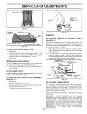
... should not be required to compensate for differences in governor plate line-up. If holes "A" are aligned. If the carburetor does need adjustment, see engine manual. Do not adjust - See electrical wiring diagram in fuse. OVERSPEEDING THE ENGINE ABOVE THE FACTORY HIGH SPEED SETTING CAN BE DANGEROUS. TO REMOVE HOOD AND...
... should not be required to compensate for differences in governor plate line-up. If holes "A" are aligned. If the carburetor does need adjustment, see engine manual. Do not adjust - See electrical wiring diagram in fuse. OVERSPEEDING THE ENGINE ABOVE THE FACTORY HIGH SPEED SETTING CAN BE DANGEROUS. TO REMOVE HOOD AND...

User Manual
Page 24
...gasoline in fuel tank or storage container. placement instructions in the Service and Adjustments section of this manual). • Lubricate as shown in the Customer Responsibilities section of this manual. • Be sure that does not retain moisture. ENGINE FUEL SYSTEM IMPORTANT: IT IS ... tractor will not be disconnected and battery cleaned thoroughly (see "TO CLEAN BATTERY AND TERMINALS" in the Customer Responsibilities section of this manual). • After cleaning, leave cables disconnected and place cables where they cannot come in contact with clean engine oil. (See "ENGINE...
...gasoline in fuel tank or storage container. placement instructions in the Service and Adjustments section of this manual). • Lubricate as shown in the Customer Responsibilities section of this manual. • Be sure that does not retain moisture. ENGINE FUEL SYSTEM IMPORTANT: IT IS ... tractor will not be disconnected and battery cleaned thoroughly (see "TO CLEAN BATTERY AND TERMINALS" in the Customer Responsibilities section of this manual). • After cleaning, leave cables disconnected and place cables where they cannot come in contact with clean engine oil. (See "ENGINE...

User Manual
Page 26
... control not set at "SLOW" position for proper air pressure. 6. Faulty operator-safety presence control system. when operator leaves seat with blades listed in this manual. 11. Check wiring, switches and connections. Replace blade. Place throttle control in clutch mechanism. 2. Clean underside of mower housing. 4. Replace with attachment clutch engaged 1. Loose...
... control not set at "SLOW" position for proper air pressure. 6. Faulty operator-safety presence control system. when operator leaves seat with blades listed in this manual. 11. Check wiring, switches and connections. Replace blade. Place throttle control in clutch mechanism. 2. Clean underside of mower housing. 4. Replace with attachment clutch engaged 1. Loose...

User Manual
Page 37
MODEL NUMBER PR1842STA PRODUCT NUMBER 954 56 82-05 DECALS 2 11 16 4 3 4 10 2 20 9 1 86 18 5 14 19 KEY PART NO. NO. Tube) NOTE: All component dimensions given ... Rh Decal Fender Reflector RH Decal Fender Reflector LH Decal Bat Dan/Psn Pad Footrest LH Pad Footrest RH Decal Handle Lft Height Adjust Manual Owner's (English) Manual Owner's (French) KEY PART NO. DESCRIPTION 1 2 3 4 5 11 6 7 8 9 10 11 - - 59192 65139 170455 59904 106732X421 278H 9040H 106108X421 170456 7152J 104757X421 144334 Cap Valve Tire...
MODEL NUMBER PR1842STA PRODUCT NUMBER 954 56 82-05 DECALS 2 11 16 4 3 4 10 2 20 9 1 86 18 5 14 19 KEY PART NO. NO. Tube) NOTE: All component dimensions given ... Rh Decal Fender Reflector RH Decal Fender Reflector LH Decal Bat Dan/Psn Pad Footrest LH Pad Footrest RH Decal Handle Lft Height Adjust Manual Owner's (English) Manual Owner's (French) KEY PART NO. DESCRIPTION 1 2 3 4 5 11 6 7 8 9 10 11 - - 59192 65139 170455 59904 106732X421 278H 9040H 106108X421 170456 7152J 104757X421 144334 Cap Valve Tire...


