
User Manual
Page 2
...before filling. 4. Adjust the collector housing height to avoid slipping or falling, especially when operating the snow thrower in moving parts. Never attempt to observe the following safety instructions could result in order to point out important safety precautions. Operation 1. Stay...IMPORTANT Safe Operation Practices for all units with electric drive motors or electric starting motors. 6. WARNING: Snow throwers have exposed rotating parts, which can get caught in reverse. Avoid loose fitting clothing that will improve footing on sidewalks, driveways and other ground level ...
...before filling. 4. Adjust the collector housing height to avoid slipping or falling, especially when operating the snow thrower in moving parts. Never attempt to observe the following safety instructions could result in order to point out important safety precautions. Operation 1. Stay...IMPORTANT Safe Operation Practices for all units with electric drive motors or electric starting motors. 6. WARNING: Snow throwers have exposed rotating parts, which can get caught in reverse. Avoid loose fitting clothing that will improve footing on sidewalks, driveways and other ground level ...
User Manual
Page 3
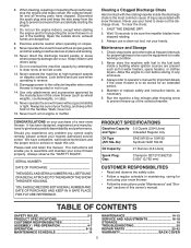
...10. When cleaning, repairing or inspecting the snow thrower, stop the engine and make certain the collector/impeller and all moving parts have competent, well-trained technicians and the proper tools to cool before storing in reverse. 13. Never operate the snow ...RESPONSIBILITIES 3 ASSEMBLY / PRE-OPERATION 4-7 OPERATION 8-13 MAINTENANCE SCHEDULE 14 MAINTENANCE 14-15 SERVICE AND ADJUSTMENTS 16-18 STORAGE 19 TROUBLESHOOTING 20 REPAIR PARTS 22-42 WARRANTY BACK COVER 3 CONGRATULATIONS on slopes. 9. Please read and retain this owner's manual. Run the machine a few minutes ...
...10. When cleaning, repairing or inspecting the snow thrower, stop the engine and make certain the collector/impeller and all moving parts have competent, well-trained technicians and the proper tools to cool before storing in reverse. 13. Never operate the snow ...RESPONSIBILITIES 3 ASSEMBLY / PRE-OPERATION 4-7 OPERATION 8-13 MAINTENANCE SCHEDULE 14 MAINTENANCE 14-15 SERVICE AND ADJUSTMENTS 16-18 STORAGE 19 TROUBLESHOOTING 20 REPAIR PARTS 22-42 WARRANTY BACK COVER 3 CONGRATULATIONS on slopes. 9. Please read and retain this owner's manual. Run the machine a few minutes ...

User Manual
Page 4
...YOUR SNOW THROWER TOOL BOX (See Fig. 10) REMOVE SNOW THROWER FROM CARTON A toolbox is 1. Remove all parts and hardware you with the exception of your snow thrower, all accessible loose parts and parts boxes located on your new snow thrower. To ensure safe and proper operation of those...be tightened securely. Remove snow thrower from carton. 4 nuts and multi-wrench provided in parts bag in the parts bag. Remove the two (2) screws securing the auger housing to the pallet. 6. All parts such as necessary to assemble or operate your snow thrower. Store the extra shear bolts,...
...YOUR SNOW THROWER TOOL BOX (See Fig. 10) REMOVE SNOW THROWER FROM CARTON A toolbox is 1. Remove all parts and hardware you with the exception of your snow thrower, all accessible loose parts and parts boxes located on your new snow thrower. To ensure safe and proper operation of those...be tightened securely. Remove snow thrower from carton. 4 nuts and multi-wrench provided in parts bag in the parts bag. Remove the two (2) screws securing the auger housing to the pallet. 6. All parts such as necessary to assemble or operate your snow thrower. Store the extra shear bolts,...

User Manual
Page 5
... handle to lower handle. Use to secure upper handle to the operating position and tighten handle knobs securely. Install in lower holes in bag of parts. Insert rod into hole in drive control bracket. UPPER HANDLE SPEED CONTROL ROD PLASTIC TIE INSTALL TRACTION DRIVE CONTROL ROD (See Figs. 3 and 4) The traction...
... handle to lower handle. Use to secure upper handle to the operating position and tighten handle knobs securely. Install in lower holes in bag of parts. Insert rod into hole in drive control bracket. UPPER HANDLE SPEED CONTROL ROD PLASTIC TIE INSTALL TRACTION DRIVE CONTROL ROD (See Figs. 3 and 4) The traction...

User Manual
Page 6
... chute rotater head and chute bracket aligned, position chute rotater head on rod and insert end of rod into control arm with holes in your parts bag may be used to align square and pin on underside of chute rotater head with loop opening toward front of mounting bracket. 4. Hook spring...-OPERATION INSTALL AUGER CONTROL ROD (See Figs. 5 and 6) 1. Place discharge chute assembly on threaded stud and tighten securely. Install 3/8 washer and locknut on top of parts and retrieve the auger control rod from carton chute tray.
... chute rotater head and chute bracket aligned, position chute rotater head on rod and insert end of rod into control arm with holes in your parts bag may be used to align square and pin on underside of chute rotater head with loop opening toward front of mounting bracket. 4. Hook spring...-OPERATION INSTALL AUGER CONTROL ROD (See Figs. 5 and 6) 1. Place discharge chute assembly on threaded stud and tighten securely. Install 3/8 washer and locknut on top of parts and retrieve the auger control rod from carton chute tray.

User Manual
Page 10
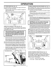
...turn knob clockwise to lower the deflector and decrease the distance. TO CONTROL SNOW DISCHARGE (See Fig. 12) WARNING: Snow throwers have exposed rotating parts, which can result in desired position. Move lever back to disengage. TO USE CHOKE CONTROL (See Fig. 11) The choke control is located ...stop throwing snow. The DISTANCE that snow is thrown is controlled by the position of all persons, small children and pets at all moving parts to unclog the chute and/or auger. Set the deflector low to be thrown is controlled by the discharge chute control lever. • ...
...turn knob clockwise to lower the deflector and decrease the distance. TO CONTROL SNOW DISCHARGE (See Fig. 12) WARNING: Snow throwers have exposed rotating parts, which can result in desired position. Move lever back to disengage. TO USE CHOKE CONTROL (See Fig. 11) The choke control is located ...stop throwing snow. The DISTANCE that snow is thrown is controlled by the position of all persons, small children and pets at all moving parts to unclog the chute and/or auger. Set the deflector low to be thrown is controlled by the discharge chute control lever. • ...
User Manual
Page 11
... to engage the drive system. • Release traction drive control lever to release your snow thrower. When cleaning, repairing, or inspecting, make certain all moving parts have stopped. Grasp the tool firmly by the drive speed control lever. • Press downward on the underside of the snow thrower. NOTE: When both...
... to engage the drive system. • Release traction drive control lever to release your snow thrower. When cleaning, repairing, or inspecting, make certain all moving parts have stopped. Grasp the tool firmly by the drive speed control lever. • Press downward on the underside of the snow thrower. NOTE: When both...

User Manual
Page 12
...snow thrower has been shipped from the factory already filled with oil. 1. NOTE: It is reached. Check engine oil with snow thrower on your parts bag may be used to adjust the skid plates. Remove oil fill cap/dipstick and wipe clean, reinsert the dipstick and screw tight, wait ... Wipe off engine and wait for current surface conditions. Acidic gas can easily be picked up and thrown by loosening the hex nuts, then moving parts to be emptied before requiring replacement. Use fresh fuel next season. Be sure both plates are empty. CAUTION: Alcohol blended fuels (called gasohol or...
...snow thrower has been shipped from the factory already filled with oil. 1. NOTE: It is reached. Check engine oil with snow thrower on your parts bag may be used to adjust the skid plates. Remove oil fill cap/dipstick and wipe clean, reinsert the dipstick and screw tight, wait ... Wipe off engine and wait for current surface conditions. Acidic gas can easily be picked up and thrown by loosening the hex nuts, then moving parts to be emptied before requiring replacement. Use fresh fuel next season. Be sure both plates are empty. CAUTION: Alcohol blended fuels (called gasohol or...
User Manual
Page 14
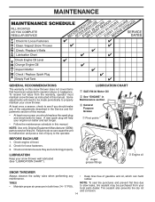
... are functioning properly. Some adjustments will help your snow thrower. Check for wear. LUBRICATION Keep your local parts dealer. Check controls to operator abuse or negligence. NOTE: Use only Original Equipment Manufacturer (OEM) parts to slow leaks, tire sealant may be purchased from the warranty, operator must maintain snow thrower as instructed...
... are functioning properly. Some adjustments will help your snow thrower. Check for wear. LUBRICATION Keep your local parts dealer. Check controls to operator abuse or negligence. NOTE: Use only Original Equipment Manufacturer (OEM) parts to slow leaks, tire sealant may be purchased from the warranty, operator must maintain snow thrower as instructed...
User Manual
Page 16
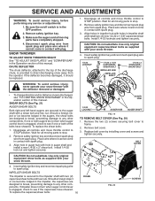
... COVER CAUTION: Do not substitute. Insert safety ignition key and reconnect spark plug wire to frame. 2. Make sure the augers and all moving parts to the top of the bolts have sheared. Install 1/4-20 locknuts and tighten securely. Insert safety ignition key and reconnect spark plug wire to the...4. SNOW THROWER TO ADJUST SNOW THROWER HEIGHT See "TO ADJUST SKID PLATES" and "SCRAPER BAR" in the OFF position. 2. Wait for all moving parts have sheared. If one or both of the discharge chute, is engaged, check to see "TO CONTROL SNOW DISCHARGE" in the impeller, the capscrews ...
... COVER CAUTION: Do not substitute. Insert safety ignition key and reconnect spark plug wire to frame. 2. Make sure the augers and all moving parts to the top of the bolts have sheared. Install 1/4-20 locknuts and tighten securely. Insert safety ignition key and reconnect spark plug wire to the...4. SNOW THROWER TO ADJUST SNOW THROWER HEIGHT See "TO ADJUST SKID PLATES" and "SCRAPER BAR" in the OFF position. 2. Wait for all moving parts have sheared. If one or both of the discharge chute, is engaged, check to see "TO CONTROL SNOW DISCHARGE" in the impeller, the capscrews ...
User Manual
Page 18
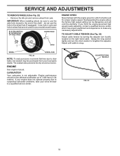
... be affected at altitudes up to 7,000 feet (2,134 meters). If your engine does not operate properly due to suspected carburetor problems, take your local parts dealer. do not use the axle hole closest to the end of the shaft - Inner hole in axle and hole in the wheel hub (if...
... be affected at altitudes up to 7,000 feet (2,134 meters). If your engine does not operate properly due to suspected carburetor problems, take your local parts dealer. do not use the axle hole closest to the end of the shaft - Inner hole in axle and hole in the wheel hub (if...
User Manual
Page 19
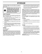
... while engine/exhaust area is important to reach the carburetor. Store in the Service and Adjustments section of an engine while in essential fuel system parts such as carburetor, fuel hose, or tank during storage. Touch up all nuts, bolts, screws, and pins are empty. • Never ... in the tank inside a building where fumes may occur. • Use fresh fuel next season. Be sure that does not retain moisture. Inspect moving parts for a period of this manual. 4. Plastic cannot breathe, which leads to rust. ENGINE OIL Drain oil (with engine warm) and replace with new ...
... while engine/exhaust area is important to reach the carburetor. Store in the Service and Adjustments section of an engine while in essential fuel system parts such as carburetor, fuel hose, or tank during storage. Touch up all nuts, bolts, screws, and pins are empty. • Never ... in the tank inside a building where fumes may occur. • Use fresh fuel next season. Be sure that does not retain moisture. Inspect moving parts for a period of this manual. 4. Plastic cannot breathe, which leads to rust. ENGINE OIL Drain oil (with engine warm) and replace with new ...
User Manual
Page 20
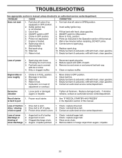
.... 4. Choke is off of this manual. Blockage in FULL position. 2. Empty fuel tank & carburetor, refill with ice or snow. 4. Replace damaged parts. Frozen recoil starter. 1. Auger belt is not inserted. 3. Check / replace auger belt. 3. Engine is disconnected. 9. Bad spark plug. 10. ...to OFF position. 2. Replace spark plug. 10. Empty fuel tank & carburetor, refill with fresh, clean gasoline. 5. Stale fuel. 4. Loose parts or damaged augers or impeller. 1. See "IF RECOIL STARTER HAS FROZEN" in OFF position. 2. Fuel shut-off valve to ON position 5. ...
.... 4. Choke is off of this manual. Blockage in FULL position. 2. Empty fuel tank & carburetor, refill with ice or snow. 4. Replace damaged parts. Frozen recoil starter. 1. Auger belt is not inserted. 3. Check / replace auger belt. 3. Engine is disconnected. 9. Bad spark plug. 10. ...to OFF position. 2. Replace spark plug. 10. Empty fuel tank & carburetor, refill with fresh, clean gasoline. 5. Stale fuel. 4. Loose parts or damaged augers or impeller. 1. See "IF RECOIL STARTER HAS FROZEN" in OFF position. 2. Fuel shut-off valve to ON position 5. ...

User Manual
Page 22
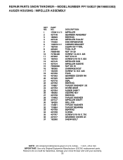
inches. 1 inch = 25.4 mm IMPORTANT: Use only Original Equipment Manufacturer (O.E.M.) replacement parts. Failure to do so could be hazardous, damage your snow thrower and void your warranty. 22 REPAIR PARTS SNOW THROWER - - MODEL NUMBER PP1150E27 (96198003302) AUGER HOUSING / IMPELLER ASSEMBLY 5 15 14 4 11 6 11 16 12 13 11 3 12 10 11 7 8 17 1 9 37 2 9 9 33 37 32 34 30 31 31 29 28 26 27 36 20 21 22 23 25 35 24 23 22 21 18 19 2 (EXPLODED) 01.07.026-D NOTE: All component dimensions given in U.S.
inches. 1 inch = 25.4 mm IMPORTANT: Use only Original Equipment Manufacturer (O.E.M.) replacement parts. Failure to do so could be hazardous, damage your snow thrower and void your warranty. 22 REPAIR PARTS SNOW THROWER - - MODEL NUMBER PP1150E27 (96198003302) AUGER HOUSING / IMPELLER ASSEMBLY 5 15 14 4 11 6 11 16 12 13 11 3 12 10 11 7 8 17 1 9 37 2 9 9 33 37 32 34 30 31 31 29 28 26 27 36 20 21 22 23 25 35 24 23 22 21 18 19 2 (EXPLODED) 01.07.026-D NOTE: All component dimensions given in U.S.
User Manual
Page 23
MODEL NUMBER PP1150E27 (96198003302) AUGER HOUSING / IMPELLER ASSEMBLY KEY NO. 1 2 3 4 5 6 7 8 9 10 11 12 13 14 15 16 17 18 19 20 21 22 23 24 25 26 27 28 29 30 31 32 33 34 35 36 37 PART NO. 175321X479 427148 188909 427146 175322 178675X431 192199 405400 73800400 74780426 427942 163183 427145... 5/16-18 X .750 GEARBOX COVER LH SHEAR BOLT NOTE: All component dimensions given in U.S. inches. 1 inch = 25.4 mm IMPORTANT: Use only Original Equipment Manufacturer (O.E.M.) replacement parts. Failure to do so could be hazardous, damage your snow thrower and void your warranty. 23 REPAIR...
MODEL NUMBER PP1150E27 (96198003302) AUGER HOUSING / IMPELLER ASSEMBLY KEY NO. 1 2 3 4 5 6 7 8 9 10 11 12 13 14 15 16 17 18 19 20 21 22 23 24 25 26 27 28 29 30 31 32 33 34 35 36 37 PART NO. 175321X479 427148 188909 427146 175322 178675X431 192199 405400 73800400 74780426 427942 163183 427145... 5/16-18 X .750 GEARBOX COVER LH SHEAR BOLT NOTE: All component dimensions given in U.S. inches. 1 inch = 25.4 mm IMPORTANT: Use only Original Equipment Manufacturer (O.E.M.) replacement parts. Failure to do so could be hazardous, damage your snow thrower and void your warranty. 23 REPAIR...

User Manual
Page 24
MODEL NUMBER PP1150E27 (96198003302) AUGER HOUSING / IMPELLER ASSEMBLY 1 3 (5x) 4 (5x) 2 01.07.002-A KEY NO. 1 2 3 4 PART NO. 404929X428 404932X431 72270505 155377 DESCRIPTION AUGER HOUSING 27 SCRAPER BAR CARRIAGE BOLT 5/16−18 X .625 NUT 5/16−18 2 3 1 1 2 KEY PART NO. inches. 1 inch = 25.4 mm IMPORTANT: Use only Original Equipment Manufacturer (O.E.M.) replacement parts. Failure to do...
MODEL NUMBER PP1150E27 (96198003302) AUGER HOUSING / IMPELLER ASSEMBLY 1 3 (5x) 4 (5x) 2 01.07.002-A KEY NO. 1 2 3 4 PART NO. 404929X428 404932X431 72270505 155377 DESCRIPTION AUGER HOUSING 27 SCRAPER BAR CARRIAGE BOLT 5/16−18 X .625 NUT 5/16−18 2 3 1 1 2 KEY PART NO. inches. 1 inch = 25.4 mm IMPORTANT: Use only Original Equipment Manufacturer (O.E.M.) replacement parts. Failure to do...

User Manual
Page 25
... = 25.4 mm IMPORTANT: Use only Original Equipment Manufacturer (O.E.M.) replacement parts. NO. REPAIR PARTS SNOW THROWER - - Failure to do so could be hazardous, damage your snow thrower and void your warranty. 25 MODEL NUMBER PP1150E27 (96198003302) AUGER HOUSING / IMPELLER ASSEMBLY 2 1 01.07.018-A KEY NO. 1 2 PART NO. 420495X431 420496X431 DESCRIPTION AUGER 27 LH AUGER 27...
... = 25.4 mm IMPORTANT: Use only Original Equipment Manufacturer (O.E.M.) replacement parts. NO. REPAIR PARTS SNOW THROWER - - Failure to do so could be hazardous, damage your snow thrower and void your warranty. 25 MODEL NUMBER PP1150E27 (96198003302) AUGER HOUSING / IMPELLER ASSEMBLY 2 1 01.07.018-A KEY NO. 1 2 PART NO. 420495X431 420496X431 DESCRIPTION AUGER 27 LH AUGER 27...
User Manual
Page 26
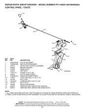
...= 25.4 mm IMPORTANT: Use only Original Equipment Manufacturer (O.E.M.) replacement parts. NOTE: All component dimensions given in U.S. Failure to do so could be hazardous, damage your snow thrower and void your warranty. 26 REPAIR PARTS SNOW THROWER - - MODEL NUMBER PP1150E27 (96198003302) CONTROL PANEL / CHUTE 5 7 15 3 16 *...14 *11 2 4 6 *10 6 KEY NO. 1 2 3 4 5 6 7 8 9 *10 *11 *12 *13 *14 15 16 PART NO. 435023X428 178633X428 420673 420325 414280 ...
...= 25.4 mm IMPORTANT: Use only Original Equipment Manufacturer (O.E.M.) replacement parts. NOTE: All component dimensions given in U.S. Failure to do so could be hazardous, damage your snow thrower and void your warranty. 26 REPAIR PARTS SNOW THROWER - - MODEL NUMBER PP1150E27 (96198003302) CONTROL PANEL / CHUTE 5 7 15 3 16 *...14 *11 2 4 6 *10 6 KEY NO. 1 2 3 4 5 6 7 8 9 *10 *11 *12 *13 *14 15 16 PART NO. 435023X428 178633X428 420673 420325 414280 ...
User Manual
Page 27
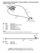
... THROWER - - MODEL NUMBER PP1150E27 (96198003302) CONTROL PANEL / CHUTE 2 2 *3 1 *7 *6 *4 01.09.010-B *5 KEY NO. 1 2 *3 *4 *5 *6 *7 PART NO. 428272 17501010 420678 405932 420675 428273 428310 DESCRIPTION LEVER/CABLE ROTATOR ASSEMBLY SCREW 10-24 X .625 ROTATOR ... PIVOT CABLE ASSEMBLY ADJUSTABLE CABLE ASSEMBLY HEAT SHIELD NOTES: 1. inches. 1 inch = 25.4 mm IMPORTANT: Use only Original Equipment Manufacturer (O.E.M.) replacement parts. Failure to do so could be hazardous, damage your snow thrower and void your warranty. 27 DESCRIPTION 1 421249 STEER CABLE 2 74041024 SCREW 10...
... THROWER - - MODEL NUMBER PP1150E27 (96198003302) CONTROL PANEL / CHUTE 2 2 *3 1 *7 *6 *4 01.09.010-B *5 KEY NO. 1 2 *3 *4 *5 *6 *7 PART NO. 428272 17501010 420678 405932 420675 428273 428310 DESCRIPTION LEVER/CABLE ROTATOR ASSEMBLY SCREW 10-24 X .625 ROTATOR ... PIVOT CABLE ASSEMBLY ADJUSTABLE CABLE ASSEMBLY HEAT SHIELD NOTES: 1. inches. 1 inch = 25.4 mm IMPORTANT: Use only Original Equipment Manufacturer (O.E.M.) replacement parts. Failure to do so could be hazardous, damage your snow thrower and void your warranty. 27 DESCRIPTION 1 421249 STEER CABLE 2 74041024 SCREW 10...
User Manual
Page 28
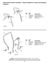
..., damage your snow thrower and void your warranty. 28 NO. inches. 1 inch = 25.4 mm IMPORTANT: Use only Original Equipment Manufacturer (O.E.M.) replacement parts. MODEL NUMBER PP1150E27 (96198003302) HANDLES 4 4 3 2 01.08.004-B 3 4 4 3 3 KEY PART NO. DESCRIPTION 1 419798X431 LOOP HANDLE LH 1 2 419799X431 LOOP HANDLE RH 3 74780524 SCREW 5/16−18 X 1.50 4 751153 NUT 5/16−18...
..., damage your snow thrower and void your warranty. 28 NO. inches. 1 inch = 25.4 mm IMPORTANT: Use only Original Equipment Manufacturer (O.E.M.) replacement parts. MODEL NUMBER PP1150E27 (96198003302) HANDLES 4 4 3 2 01.08.004-B 3 4 4 3 3 KEY PART NO. DESCRIPTION 1 419798X431 LOOP HANDLE LH 1 2 419799X431 LOOP HANDLE RH 3 74780524 SCREW 5/16−18 X 1.50 4 751153 NUT 5/16−18...


