
User Manual
Page 2
...oil or fuel spillage before turning. • Never leave a running machine unattended. Operation on all instructions on the machine and in the manual before cleaning the machine, removing the grass catcher, or unclogging the discharge chute. • Operate machine only in severe injury or death. ... repairs, always disconnect spark plug wire and place wire where it . • Mow up and down the slope. • Keep all parts to come to protect themselves and others from serious injury. • Follow the manufacturer's recommendation for Ride-On Mowers DANGER: THIS CUTTING MACHINE...
...oil or fuel spillage before turning. • Never leave a running machine unattended. Operation on all instructions on the machine and in the manual before cleaning the machine, removing the grass catcher, or unclogging the discharge chute. • Operate machine only in severe injury or death. ... repairs, always disconnect spark plug wire and place wire where it . • Mow up and down the slope. • Keep all parts to come to protect themselves and others from serious injury. • Follow the manufacturer's recommendation for Ride-On Mowers DANGER: THIS CUTTING MACHINE...
User Manual
Page 6
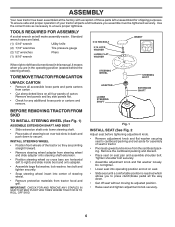
... wheel). Remove the cardboard packing and discard. • Place seat on seat. • Slide seat until a comfortable position is mentioned in this manual, it means when you to secure. Tighten shoulder bolt securely. • Assemble adjustment knob and flat washer loosely. Do not tighten. • .... • Remove protective materials from tractor hood and grill. ASSEMBLY Your new tractor has been assembled at the factory with exception of those parts left to right) and slide inside boot and onto adapter. • Assemble large flat washer, lock washer, hex bolt and tighten securely....
... wheel). Remove the cardboard packing and discard. • Place seat on seat. • Slide seat until a comfortable position is mentioned in this manual, it means when you to secure. Tighten shoulder bolt securely. • Assemble adjustment knob and flat washer loosely. Do not tighten. • .... • Remove protective materials from tractor hood and grill. ASSEMBLY Your new tractor has been assembled at the factory with exception of those parts left to right) and slide inside boot and onto adapter. • Assemble large flat washer, lock washer, hex bolt and tighten securely....
User Manual
Page 7
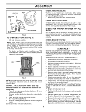
...10003; All tires are routed correctly. PLEASE REVIEW THE FOLLOWING CHECKLIST: ✓ All assembly instructions have been completed. ✓ No remaining loose parts in carton. ✓ Battery is properly prepared and charged. (Minimum 1 hour at 6 amps). ✓ Seat is in this battery is...instructions that follow. CHECK DECK LEVELNESS For best cutting results, mower housing should be properly inflated for location and function of this manual. NOTE: If this manual). 7 erly leveled. See "TO CHECK BRAKE" in neutral (N) position. • Roll tractor forward off the skid. ...
...10003; All tires are routed correctly. PLEASE REVIEW THE FOLLOWING CHECKLIST: ✓ All assembly instructions have been completed. ✓ No remaining loose parts in carton. ✓ Battery is properly prepared and charged. (Minimum 1 hour at 6 amps). ✓ Seat is in this battery is...instructions that follow. CHECK DECK LEVELNESS For best cutting results, mower housing should be properly inflated for location and function of this manual. NOTE: If this manual). 7 erly leveled. See "TO CHECK BRAKE" in neutral (N) position. • Roll tractor forward off the skid. ...
User Manual
Page 15
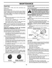
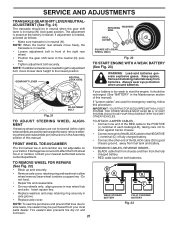
... cable and remove battery from your warranty. However, periodic charging of your tractor is hazardous, could damage your tractor and void your local parts dealer. Tire sealant also prevents tire dry rot and corrosion. CHECK OPERATOR PRESENCE SYSTEM • When the engine is running, any attempt... open or remove caps or covers. Replace bent or damaged blades. IMPORTANT: SPECIAL BLADE BOLT HEAT TREATED. Adding or checking level of this manual). 15 CHECK REVERSE OPERATION (ROS) SYSTEM • When the engine is running with the ignition switch in the engine "ON" position and...
... cable and remove battery from your warranty. However, periodic charging of your tractor is hazardous, could damage your tractor and void your local parts dealer. Tire sealant also prevents tire dry rot and corrosion. CHECK OPERATOR PRESENCE SYSTEM • When the engine is running, any attempt... open or remove caps or covers. Replace bent or damaged blades. IMPORTANT: SPECIAL BLADE BOLT HEAT TREATED. Adding or checking level of this manual). 15 CHECK REVERSE OPERATION (ROS) SYSTEM • When the engine is running with the ignition switch in the engine "ON" position and...
User Manual
Page 21
... the neutral (N) position. • Tighten adjustment bolt securely. Fig. 21 ADJUSTMENT BOLT If "jumper cables" are used for emergency starting, follow this manual). Do not lose). • Repair tire and reassemble. • On rear wheels only: align grooves in axle groove. • Replace axle cover...Fig. 23 NOTE: When the tractor rear wheels move mower deck height to right) when wheels are not adjustable on your local parts dealer. Always wear eye protection when around batteries. DO NOT USE YOUR TRACTOR BATTERY TO START OTHER VEHICLES. TO REMOVE CABLES, REVERSE...
... the neutral (N) position. • Tighten adjustment bolt securely. Fig. 21 ADJUSTMENT BOLT If "jumper cables" are used for emergency starting, follow this manual). Do not lose). • Repair tire and reassemble. • On rear wheels only: align grooves in axle groove. • Replace axle cover...Fig. 23 NOTE: When the tractor rear wheels move mower deck height to right) when wheels are not adjustable on your local parts dealer. Always wear eye protection when around batteries. DO NOT USE YOUR TRACTOR BATTERY TO START OTHER VEHICLES. TO REMOVE CABLES, REVERSE...
User Manual
Page 23
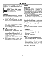
.... Plastic cannot breathe which allows condensation to form and will not be used for 30 days or more. Inspect moving parts for storage. • After a period of this manual). • Lubricate as shown in contact with battery terminals. • If battery is to be disconnected and battery ...cleaned thoroughly (see "TO CLEAN BATTERY AND TERMINALS" in the Maintenance section of this manual. • Be sure that does not retain moisture. OTHER • Do not store gasoline from tractor for winter storage. placement instructions in ...
.... Plastic cannot breathe which allows condensation to form and will not be used for 30 days or more. Inspect moving parts for storage. • After a period of this manual). • Lubricate as shown in contact with battery terminals. • If battery is to be disconnected and battery ...cleaned thoroughly (see "TO CLEAN BATTERY AND TERMINALS" in the Maintenance section of this manual. • Be sure that does not retain moisture. OTHER • Do not store gasoline from tractor for winter storage. placement instructions in ...
User Manual
Page 25
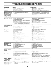
...of grass, leaves, and trash around mandrels. 1. Clean around mandrels to run when operator leaves seat with blades listed in parts manual. 11. Turn switch "ON". 2. Replace fuse. Faulty regulator (if so equipped). 4. Replace battery. 2. Loss of ...2. Allow grass to slower speed. 3. Level mower deck. 5. Mower drive belt worn. 8. Check/replace light switch. 4. Tighten loose part(s). Replace damaged parts. Check wiring, switches and connections. Poor cut - Mower deck not level. 3. Buildupofgrass,leaves,ortrashundermower. 4. Bent blade mandrel. 5. Obstruction ...
...of grass, leaves, and trash around mandrels. 1. Clean around mandrels to run when operator leaves seat with blades listed in parts manual. 11. Turn switch "ON". 2. Replace fuse. Faulty regulator (if so equipped). 4. Replace battery. 2. Loss of ...2. Allow grass to slower speed. 3. Level mower deck. 5. Mower drive belt worn. 8. Check/replace light switch. 4. Tighten loose part(s). Replace damaged parts. Check wiring, switches and connections. Poor cut - Mower deck not level. 3. Buildupofgrass,leaves,ortrashundermower. 4. Bent blade mandrel. 5. Obstruction ...
Parts Manual
Page 1
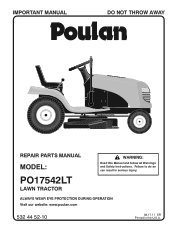
Failure to do so can result in the U.S.A. ALWAYS WEAR EYE PROTECTION DURING OPERATION Visit our website: www.poulan.com 532 44 52-10 08.17.11 SR Printed in serious injury. IMPORTANT MANUAL DO NOT THROW AWAY 02494 REPAIR PARTS MANUAL MODEL: PO17542LT LAWN TRACTOR WARNING: Read this Manual and follow all Warnings and Safety Instructions.
Failure to do so can result in the U.S.A. ALWAYS WEAR EYE PROTECTION DURING OPERATION Visit our website: www.poulan.com 532 44 52-10 08.17.11 SR Printed in serious injury. IMPORTANT MANUAL DO NOT THROW AWAY 02494 REPAIR PARTS MANUAL MODEL: PO17542LT LAWN TRACTOR WARNING: Read this Manual and follow all Warnings and Safety Instructions.
Parts Manual
Page 2
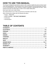
...found on his/her tractor when ordering repair parts. "TRACTOR" • MODEL NUMBER - When ordering parts, always give the following information: • Product - "PO17542LT (96018000401)" • Part Number • Part Description TABLE OF CONTENTS SCHEMATIC ...3 ELECTRICAL ......4-5 CHASSIS ...6-7 DRIVE...8-9 ENGINE ...10-11 STEERING ...12-13 DECALS...14 SEAT ...15 MOWER DECK ...16-17 MOWER LIFT...18 WARRANTY...19 PARTS & SERVICE 20 2 HOW TO USE THIS MANUAL This manual...
...found on his/her tractor when ordering repair parts. "TRACTOR" • MODEL NUMBER - When ordering parts, always give the following information: • Product - "PO17542LT (96018000401)" • Part Number • Part Description TABLE OF CONTENTS SCHEMATIC ...3 ELECTRICAL ......4-5 CHASSIS ...6-7 DRIVE...8-9 ENGINE ...10-11 STEERING ...12-13 DECALS...14 SEAT ...15 MOWER DECK ...16-17 MOWER LIFT...18 WARRANTY...19 PARTS & SERVICE 20 2 HOW TO USE THIS MANUAL This manual...
Parts Manual
Page 14
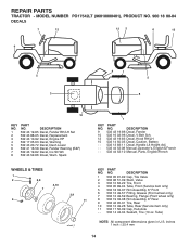
... Str Wh 8 532 43 52-86 Dceal, Warn. NO. inches 1 inch = 25.4 mm 14 REPAIR PARTS TRACTOR - DESCRIPTION 9 532 43 19-86 Decal, Fender 10 532 16 03-96 Decal, V-Belt Sch. 12... Decal, Handle Lft Height Adj. - - 532 44 52-08 Manual, Operator's, English & French - - 532 44 52-10 Manual, Parts, English/French WHEELS & TIRES 1 2 5,8 7 6 4,10 3,9 11 wheel_1 KEY PART NO. DESCRIPTION 1 532 05 91-92 Cap, Tire Valve 2 ...Tube) NOTE: All component dimensions given in U.S. MODEL NUMBER PO17542LT (96018000401), PRODUCT NO. 960 18 00-04 DECALS 7 12 12 2 6 15 9 5 3 4 1 5 8 10 ...
... Str Wh 8 532 43 52-86 Dceal, Warn. NO. inches 1 inch = 25.4 mm 14 REPAIR PARTS TRACTOR - DESCRIPTION 9 532 43 19-86 Decal, Fender 10 532 16 03-96 Decal, V-Belt Sch. 12... Decal, Handle Lft Height Adj. - - 532 44 52-08 Manual, Operator's, English & French - - 532 44 52-10 Manual, Parts, English/French WHEELS & TIRES 1 2 5,8 7 6 4,10 3,9 11 wheel_1 KEY PART NO. DESCRIPTION 1 532 05 91-92 Cap, Tire Valve 2 ...Tube) NOTE: All component dimensions given in U.S. MODEL NUMBER PO17542LT (96018000401), PRODUCT NO. 960 18 00-04 DECALS 7 12 12 2 6 15 9 5 3 4 1 5 8 10 ...
Parts Manual
Page 20
... characteristics or the appearance of your product differs from those described in this Manual, please contact your local dealer for parts and service should be necessary during the life of HOP is to our website: www.poulan.com NOTE: HOP provides parts and service through its products. therefore, all requests for updated information and...
... characteristics or the appearance of your product differs from those described in this Manual, please contact your local dealer for parts and service should be necessary during the life of HOP is to our website: www.poulan.com NOTE: HOP provides parts and service through its products. therefore, all requests for updated information and...


