User Manual
Page 7
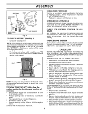
...10003; Be sure brake system is filled with fresh, clean, regular unleaded gasoline. ✓ Become familiar with the instructions that the belts are routed correctly. Be sure they are routed properly around pulleys and inside all connections are still secure and wires are shown for... between terminals) charge battery for minimum of this manual for charging instructions). • For battery and battery cable installation see that all belt keepers. ✓ Check wiring. Follow the appropriate instruction below to PSI shown on tires. PLEASE REVIEW THE FOLLOWING CHECKLIST: ✓ ...
...10003; Be sure brake system is filled with fresh, clean, regular unleaded gasoline. ✓ Become familiar with the instructions that the belts are routed correctly. Be sure they are routed properly around pulleys and inside all connections are still secure and wires are shown for... between terminals) charge battery for minimum of this manual for charging instructions). • For battery and battery cable installation see that all belt keepers. ✓ Check wiring. Follow the appropriate instruction below to PSI shown on tires. PLEASE REVIEW THE FOLLOWING CHECKLIST: ✓ ...
User Manual
Page 14
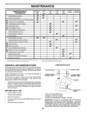
... • At least once a year you should replace the spark plug, clean or replace air filter, and check blades and belts for loose fasteners. To receive full value from the warranty, operator must maintain tractor as instructed in dirty or dusty conditions. Service...C Check/Replace Mower Blades T Lubrication Chart 0 Check Battery Level R Clean Battery and Terminals Check Transaxle Cooling Check Mower Levelness Check V-Belts Check Engine Oil Level Change Engine Oil (with maintenance-free battery. Replace blades more often when operating in this tractor does not cover items...
... • At least once a year you should replace the spark plug, clean or replace air filter, and check blades and belts for loose fasteners. To receive full value from the warranty, operator must maintain tractor as instructed in dirty or dusty conditions. Service...C Check/Replace Mower Blades T Lubrication Chart 0 Check Battery Level R Clean Battery and Terminals Check Transaxle Cooling Check Mower Levelness Check V-Belts Check Engine Oil Level Change Engine Oil (with maintenance-free battery. Replace blades more often when operating in this tractor does not cover items...
User Manual
Page 16
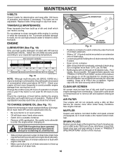
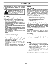
...dipstick tube. Tighten oil fill cap/dipstick securely each mowing season or after every 25 hours of this manual. 16 Do not overfill. MAINTENANCE V-BELTS Check V-belts for checking level. SAE VISCOSITY GRADES 5W-30 SAE 30 F -20 0 30 32 40 60 80 100 C -30 -20 -10 0... dirt and stubborn dried gum fibers. Pour slowly. Tighten cap onto the tube securely when finished. See engine manual. The belts are not adjustable. Replace belts if they will drain more than 13 Ft. TRANSAXLE MAINTENANCE Keep transaxle free from wear. To prevent possible damage to seals,...
...dipstick tube. Tighten oil fill cap/dipstick securely each mowing season or after every 25 hours of this manual. 16 Do not overfill. MAINTENANCE V-BELTS Check V-belts for checking level. SAE VISCOSITY GRADES 5W-30 SAE 30 F -20 0 30 32 40 60 80 100 C -30 -20 -10 0... dirt and stubborn dried gum fibers. Pour slowly. Tighten cap onto the tube securely when finished. See engine manual. The belts are not adjustable. Replace belts if they will drain more than 13 Ft. TRANSAXLE MAINTENANCE Keep transaxle free from wear. To prevent possible damage to seals,...
User Manual
Page 18
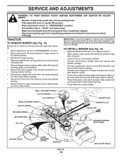
... wire where it cannot come in "DISENGAGED" position. • Move attachment lift lever forward to lower mower to its lowest position. • Roll belt off engine pulley. • Remove small retainer spring, and remove clutch spring off pulley bolt. • Remove large retainer spring, slide collar off ... deck and secure with retainer springs.. • Connect suspension arms to rear deck brackets and secure with small retainer spring. • Install belt onto engine pulley. IMPORTANT: IF AN ATTACHMENT OTHER THAN THE MOWER DECK IS TO BE MOUNTED ON THE TRACTOR, REMOVE THE FRONT LINKS AND...
... wire where it cannot come in "DISENGAGED" position. • Move attachment lift lever forward to lower mower to its lowest position. • Roll belt off engine pulley. • Remove small retainer spring, and remove clutch spring off pulley bolt. • Remove large retainer spring, slide collar off ... deck and secure with retainer springs.. • Connect suspension arms to rear deck brackets and secure with small retainer spring. • Install belt onto engine pulley. IMPORTANT: IF AN ATTACHMENT OTHER THAN THE MOWER DECK IS TO BE MOUNTED ON THE TRACTOR, REMOVE THE FRONT LINKS AND...

User Manual
Page 20
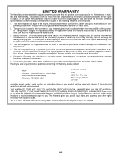
.... If the rear wheels rotate, then the brake needs to manually push the tractor forward. Remove belt upwards from transaxle pulley by : 1. Engage parking brake. TO REPLACE MOTION DRIVE BELT (See Fig. 20) Park the tractor on level surface. Park tractor on a level, dry concrete...(See "TO INSTALL MOWER" in this section of this section of tractor. Contact a qualified service center. NOTE: Observe entire motion drive belt and position of removal instruc- tion of left footrest. ENGINE PULLEY CLUTCHING IDLER STATIONARY IDLER CENTER SPAN KEEPER TRANSAXLE PULLEY Fig. 20 20 ...
.... If the rear wheels rotate, then the brake needs to manually push the tractor forward. Remove belt upwards from transaxle pulley by : 1. Engage parking brake. TO REPLACE MOTION DRIVE BELT (See Fig. 20) Park the tractor on level surface. Park tractor on a level, dry concrete...(See "TO INSTALL MOWER" in this section of this section of tractor. Contact a qualified service center. NOTE: Observe entire motion drive belt and position of removal instruc- tion of left footrest. ENGINE PULLEY CLUTCHING IDLER STATIONARY IDLER CENTER SPAN KEEPER TRANSAXLE PULLEY Fig. 20 20 ...
User Manual
Page 23
... the Service and Adjustments section of this manual). • Lubricate as shown in the Maintenance section of this manual). • Inspect and replace belts, if necessary (See belt re- Always follow the mix ratio found on concrete or damp surfaces. Do not empty the gas tank and carburetor if using fuel stabilizer...
... the Service and Adjustments section of this manual). • Lubricate as shown in the Maintenance section of this manual). • Inspect and replace belts, if necessary (See belt re- Always follow the mix ratio found on concrete or damp surfaces. Do not empty the gas tank and carburetor if using fuel stabilizer...
User Manual
Page 25
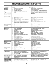
...deck not level. 3. Buildupofgrass,leaves,ortrashundermower. 4. Clogged mower deck vent holes from buildup 11. Tighten blade bolt. 2. Replace mower drive belt. 3. Engine speed too slow. 1. Level mower deck. 5. Buildup of mower housing. 8. Clean underside of grass, leaves and trash ... 4. Replace alternator. Loss of mower housing. 4. See "CLEANING" in "FAST" position. 2. Replace blade mandrel. 3. Worn/damaged mower drive belt. 3. Clean underside of drive Engine "backfires" when turning engine "OFF" Engine dies when tractor is engaged. 1. Travel speed too fast. 2....
...deck not level. 3. Buildupofgrass,leaves,ortrashundermower. 4. Clogged mower deck vent holes from buildup 11. Tighten blade bolt. 2. Replace mower drive belt. 3. Engine speed too slow. 1. Level mower deck. 5. Buildup of mower housing. 8. Clean underside of grass, leaves and trash ... 4. Replace alternator. Loss of mower housing. 4. See "CLEANING" in "FAST" position. 2. Replace blade mandrel. 3. Worn/damaged mower drive belt. 3. Clean underside of drive Engine "backfires" when turning engine "OFF" Engine dies when tractor is engaged. 1. Travel speed too fast. 2....
User Manual
Page 26
... maintained in manufacture, during the first ninety (90) days of the purchaser. This Warranty does not apply to any power equipment unit or attachment are belts, blades, blade adapters, normal wear, normal adjustments, standard hardware and normal maintenance. 7. This Warranty is requested by the purchaser unless such return is subject to...
... maintained in manufacture, during the first ninety (90) days of the purchaser. This Warranty does not apply to any power equipment unit or attachment are belts, blades, blade adapters, normal wear, normal adjustments, standard hardware and normal maintenance. 7. This Warranty is requested by the purchaser unless such return is subject to...
Parts Manual
Page 9
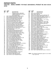
MODEL NUMBER PO17542LT (96018000401), PRODUCT NO. 960 18 00-04 DRIVE KEY PART NO. Sh. 3/8-16 x 1-1/2 Gr. 5 51 873 68 06-00 Nut Crownlock...Link Clutch 55 532 10 57-09 Spring Return Clutch 6 75 56 817 06 06-20 Screw 3/8-16 x 1-1/4 57 532 13 82-55 V-Belt Ground Drive 62 532 12 48-72 Cover Pedal Blk Round KEY PART NO. NO. inches 1 inch = 25.4 mm 9 DESCRIPTION 63 532 ...168 532 16 54-92 Bolt Shoulder 5/16-18 x .561 169 532 16 55-80 Plate Fastening 170 532 18 74-14 Keeper Belt Transaxle Gear 197 532 16 96-13 Nyliner Snap-In 198 532 16 95-93 Washer Nyliner 202 872 11 06-14 Bolt RdHd 3/8-16...
MODEL NUMBER PO17542LT (96018000401), PRODUCT NO. 960 18 00-04 DRIVE KEY PART NO. Sh. 3/8-16 x 1-1/2 Gr. 5 51 873 68 06-00 Nut Crownlock...Link Clutch 55 532 10 57-09 Spring Return Clutch 6 75 56 817 06 06-20 Screw 3/8-16 x 1-1/4 57 532 13 82-55 V-Belt Ground Drive 62 532 12 48-72 Cover Pedal Blk Round KEY PART NO. NO. inches 1 inch = 25.4 mm 9 DESCRIPTION 63 532 ...168 532 16 54-92 Bolt Shoulder 5/16-18 x .561 169 532 16 55-80 Plate Fastening 170 532 18 74-14 Keeper Belt Transaxle Gear 197 532 16 96-13 Nyliner Snap-In 198 532 16 95-93 Washer Nyliner 202 872 11 06-14 Bolt RdHd 3/8-16...
Parts Manual
Page 14
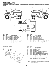
... (10 oz. Tube) NOTE: All component dimensions given in U.S. DESCRIPTION 9 532 43 19-86 Decal, Fender 10 532 16 03-96 Decal, V-Belt Sch. 12 532 43 19-83 Decal, Hood RH/LH 15 532 14 50-05 Decal, Caution, Battery - - 532 13 83-11 Decal, ...44 52-08 Manual, Operator's, English & French - - 532 44 52-10 Manual, Parts, English/French WHEELS & TIRES 1 2 5,8 7 6 4,10 3,9 11 wheel_1 KEY PART NO. MODEL NUMBER PO17542LT (96018000401), PRODUCT NO. 960 18 00-04 DECALS 7 12 12 2 6 15 9 5 3 4 1 5 8 10 KEY PART NO. inches 1 inch = 25.4 mm 14 REPAIR PARTS TRACTOR...
... (10 oz. Tube) NOTE: All component dimensions given in U.S. DESCRIPTION 9 532 43 19-86 Decal, Fender 10 532 16 03-96 Decal, V-Belt Sch. 12 532 43 19-83 Decal, Hood RH/LH 15 532 14 50-05 Decal, Caution, Battery - - 532 13 83-11 Decal, ...44 52-08 Manual, Operator's, English & French - - 532 44 52-10 Manual, Parts, English/French WHEELS & TIRES 1 2 5,8 7 6 4,10 3,9 11 wheel_1 KEY PART NO. MODEL NUMBER PO17542LT (96018000401), PRODUCT NO. 960 18 00-04 DECALS 7 12 12 2 6 15 9 5 3 4 1 5 8 10 KEY PART NO. inches 1 inch = 25.4 mm 14 REPAIR PARTS TRACTOR...
Parts Manual
Page 17
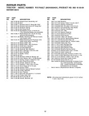
..., Retainer 59 532 14 10-43 Guard TUV Idler 67 532 10 69-32 Knob Round 68 532 14 49-59 V-Belt, 42" Mower 142 532 19 57-84 Anchor Spring Brake Mower 143 532 15 71-09 Bracket Arm Idler 42" 144... 532 15 86-34 Keeper Belt 42" Clutch Cable 145 532 16 58-88 Pulley Idler Flat 146 532 17 19-77 Bolt Carriage Idler 147 532 13...bolt/washers not included) - - 532 41 80-31 Replacement Mower, Complete NOTE: All component dimensions given in U.S. MODEL NUMBER PO17542LT (96018000401), PRODUCT NO. 960 18 00-04 MOWER DECK KEY PART NO.
..., Retainer 59 532 14 10-43 Guard TUV Idler 67 532 10 69-32 Knob Round 68 532 14 49-59 V-Belt, 42" Mower 142 532 19 57-84 Anchor Spring Brake Mower 143 532 15 71-09 Bracket Arm Idler 42" 144... 532 15 86-34 Keeper Belt 42" Clutch Cable 145 532 16 58-88 Pulley Idler Flat 146 532 17 19-77 Bolt Carriage Idler 147 532 13...bolt/washers not included) - - 532 41 80-31 Replacement Mower, Complete NOTE: All component dimensions given in U.S. MODEL NUMBER PO17542LT (96018000401), PRODUCT NO. 960 18 00-04 MOWER DECK KEY PART NO.
Parts Manual
Page 19
... dealer. Some areas do not allow the limitation of consequential damages or limitations of any parts submitted for any power equipment unit or attachment are belts, blades, blade adapters, normal wear, normal adjustments, standard hardware and normal maintenance. 7. In the event you have been properly assembled, adjusted, operated, and maintained in...
... dealer. Some areas do not allow the limitation of consequential damages or limitations of any parts submitted for any power equipment unit or attachment are belts, blades, blade adapters, normal wear, normal adjustments, standard hardware and normal maintenance. 7. In the event you have been properly assembled, adjusted, operated, and maintained in...


