

User Manual
Page 2
The blower can cause serious injury. You can be caught in moving parts. Hazard zone for thrown objects. Do not wear jewelry, loose clothing, or clothing with ... after use can throw objects violently. Read your operator's manual carefully until you completely understand and can be dangerous! Save operator's manual. Do not point blower nozzle in serious injury. Always stop unit and disconnect spark plug before operating the unit. Do not touch the muffler, muffler guard, or surrounding surfaces...
The blower can cause serious injury. You can be caught in moving parts. Hazard zone for thrown objects. Do not wear jewelry, loose clothing, or clothing with ... after use can throw objects violently. Read your operator's manual carefully until you completely understand and can be dangerous! Save operator's manual. Do not point blower nozzle in serious injury. Always stop unit and disconnect spark plug before operating the unit. Do not touch the muffler, muffler guard, or surrounding surfaces...

User Manual
Page 3
...) when starting or operating unit. They can result in the areas where fuel is designed to follow all fuel purposes. Do not point the blower nozzle in moving parts. SAFETY RULES WARNING: Failure to pick up dry material such as leaves, grass, small twigs, and bits of people ... or grass clippings from being blown or ricocheting into eyes and face which can be caught in the direction of paper. Use your unit as a blower for : D Picking up on unit. D Always wear foot protection. D Do not smoke while handling fuel or while operating the unit. -- 3 -- Wearing eye ...
...) when starting or operating unit. They can result in the areas where fuel is designed to follow all fuel purposes. Do not point the blower nozzle in moving parts. SAFETY RULES WARNING: Failure to pick up dry material such as leaves, grass, small twigs, and bits of people ... or grass clippings from being blown or ricocheting into eyes and face which can be caught in the direction of paper. Use your unit as a blower for : D Picking up on unit. D Always wear foot protection. D Do not smoke while handling fuel or while operating the unit. -- 3 -- Wearing eye ...

User Manual
Page 4
... monoxide build up fuel left in full compliance with engine stopped and spark plug disconnected. When using your unit as a blower, always install blower tubes. D Keep outside surfaces free of gasoline powered hand tools could cause blood vessel or nerve damage in this manual....cause other than those recommended by an authorized service dealer. ommended procedures described in your area, contact your unit. D Use only recommended Poulan PRO replacement parts; D Do not use for use of oil and fuel. If a spark arresting screen is completely zipped. D Never ...
... monoxide build up fuel left in full compliance with engine stopped and spark plug disconnected. When using your unit as a blower, always install blower tubes. D Keep outside surfaces free of gasoline powered hand tools could cause blood vessel or nerve damage in this manual....cause other than those recommended by an authorized service dealer. ommended procedures described in your area, contact your unit. D Use only recommended Poulan PRO replacement parts; D Do not use for use of oil and fuel. If a spark arresting screen is completely zipped. D Never ...

User Manual
Page 5
... tube as - Push lower vacuum tube into place. remove the tube. Close the zipper on the blower tube with the blower outlet groove. 6. Upper Vacuum Tube Lower Vacuum Tube 2. Latch Area Blower Outlet Latch Area Vacuum Inlet Cover 3. Hold the vacuum inlet cover open until upper vacuum tube is ...the elbow tube through the small opening is flush against the flared area of the unit to insert or remove the vacuum or blower tubes. Remove blower tube from engine. Open the zipper on the vacuum bag and in the manual and on the elbow tube is properly assembled ...
... tube as - Push lower vacuum tube into place. remove the tube. Close the zipper on the blower tube with the blower outlet groove. 6. Upper Vacuum Tube Lower Vacuum Tube 2. Latch Area Blower Outlet Latch Area Vacuum Inlet Cover 3. Hold the vacuum inlet cover open until upper vacuum tube is ...the elbow tube through the small opening is flush against the flared area of the unit to insert or remove the vacuum or blower tubes. Remove blower tube from engine. Open the zipper on the vacuum bag and in the manual and on the elbow tube is properly assembled ...
User Manual
Page 6
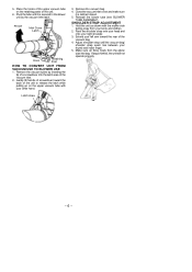
...cover and make sure it is secured to release the latch while pulling up on the retaining posts of the vacuum inlet. 2. Reinstall the blower tube (see BLOWER TUBE ASSEMBLY). Make sure air flows freely from your body and clothes. 2. Gently tilt handle of screwdriver toward the rear of a screwdriver into... latch area of the unit. 6. Latch Area 3. Hold the unit as shown with your left arm toward the back of the unit to the blower unit by inserting the tip of the vacuum bag. 4. If bag is latched closed. 5. PIVOT Inlet Cover Latch Hook Retaining Post HOW TO CONVERT...
...cover and make sure it is secured to release the latch while pulling up on the retaining posts of the vacuum inlet. 2. Reinstall the blower tube (see BLOWER TUBE ASSEMBLY). Make sure air flows freely from your body and clothes. 2. Gently tilt handle of screwdriver toward the rear of a screwdriver into... latch area of the unit. 6. Latch Area 3. Hold the unit as shown with your left arm toward the back of the unit to the blower unit by inserting the tip of the vacuum bag. 4. If bag is latched closed. 5. PIVOT Inlet Cover Latch Hook Retaining Post HOW TO CONVERT...

User Manual
Page 7
...attachments. Save this manual for future reference. Upper Lower Vacuum Tube Vacuum Tube Vacuum Bag Elbow Tube Throttle Lever Spark Plug Blower Tube Primer Button Choke Lever Fuel Mix Fill Cap Starter Rope Rear Handle THROTTLE LEVER The THROTTLE LEVER is required. CHOKE LEVER... location of hearing loss associated with contacting rotating parts, stop the engine before blowing. -- 7 -- S To reduce noise levels, operate power blowers at night when people might be disturbed. Activate the choke by pressing it and allowing it to return to 5:00 p.m., Monday though Saturday. ...
...attachments. Save this manual for future reference. Upper Lower Vacuum Tube Vacuum Tube Vacuum Bag Elbow Tube Throttle Lever Spark Plug Blower Tube Primer Button Choke Lever Fuel Mix Fill Cap Starter Rope Rear Handle THROTTLE LEVER The THROTTLE LEVER is required. CHOKE LEVER... location of hearing loss associated with contacting rotating parts, stop the engine before blowing. -- 7 -- S To reduce noise levels, operate power blowers at night when people might be disturbed. Activate the choke by pressing it and allowing it to return to 5:00 p.m., Monday though Saturday. ...

User Manual
Page 8
...S After using the unit. Call 1-800-554-6723. Poulan PRO brand synthetic oil is running. Mix gasoline and oil ... fuel next season. D Hold the unit in the starting engine, hold the unit as shown. STARTING POSITION Blower Vacuum WARNING: When starting position as illustrated. Debris such as gutters, screens, patios, grills, porches, and gardens...to the STOP position. This engine is certified to assure that alcohol blended fuels (called gasohol or using power blowers instead of unleaded gasoline. A 40:1 ratio is thoroughly mixed. Acidic gas can attract moisture which leads to...
...S After using the unit. Call 1-800-554-6723. Poulan PRO brand synthetic oil is running. Mix gasoline and oil ... fuel next season. D Hold the unit in the starting engine, hold the unit as shown. STARTING POSITION Blower Vacuum WARNING: When starting position as illustrated. Debris such as gutters, screens, patios, grills, porches, and gardens...to the STOP position. This engine is certified to assure that alcohol blended fuels (called gasohol or using power blowers instead of unleaded gasoline. A 40:1 ratio is thoroughly mixed. Acidic gas can attract moisture which leads to...

User Manual
Page 9
...lever to the position. 2. If unit still doesn't start refer to properly maintain your responsibility to insert or remove the vacuum or blower tubes. A hot muffler can be started by an authorized service dealer. Various adjustments will need to be sure the impeller blades have... STARTING A WARM ENGINE NOTE: If fuel tank is hot. 1. Starting could require pulling the starter rope many times depending on the product, Poulan PRO may not pay for replacement of damage or leaks. S Vacuum Bag -- To receive full value from the warranty, the operator must maintain...
...lever to the position. 2. If unit still doesn't start refer to properly maintain your responsibility to insert or remove the vacuum or blower tubes. A hot muffler can be started by an authorized service dealer. Various adjustments will need to be sure the impeller blades have... STARTING A WARM ENGINE NOTE: If fuel tank is hot. 1. Starting could require pulling the starter rope many times depending on the product, Poulan PRO may not pay for replacement of damage or leaks. S Vacuum Bag -- To receive full value from the warranty, the operator must maintain...

User Manual
Page 10
Install new fuel filter on your blower. reinstall parts. Fuel Line Air Filter Screws Cleaning the air filter: A dirty air filter decreases engine performance and increases fuel consumption and harmful emissions. Allow ...
Install new fuel filter on your blower. reinstall parts. Fuel Line Air Filter Screws Cleaning the air filter: A dirty air filter decreases engine performance and increases fuel consumption and harmful emissions. Allow ...

Parts List
Page 1
Choke Washer Throttle Lever Throttle Linkage Throttle Plate Carburetor Adapter Bolt Clamp--Blower Tube Screw Knob--Tube Clamp Handle Muffler Cover Ass'y. Fuel Tank Ass'y. Left Nut 1/4--20 Wire Clamp Tube -- Carburetor Carburetor Assy. (WA--229) Choke Plate ... 543 13 12 11 10 8 98 7 6 16 2 1 20 24 23 22 21 18 19 40 8 41 42 39 8 43 11 10 44 45 46 MODEL(s) BVM200 PAGE NO. 1 48 47 25 26 28 27 29 36 37 38 30 31 32 33 34 35 Ref. 1. 2. 3. 4. 5. 6. 7. 8. 9. 10. 11. 12. 13. 14. 15...
Choke Washer Throttle Lever Throttle Linkage Throttle Plate Carburetor Adapter Bolt Clamp--Blower Tube Screw Knob--Tube Clamp Handle Muffler Cover Ass'y. Fuel Tank Ass'y. Left Nut 1/4--20 Wire Clamp Tube -- Carburetor Carburetor Assy. (WA--229) Choke Plate ... 543 13 12 11 10 8 98 7 6 16 2 1 20 24 23 22 21 18 19 40 8 41 42 39 8 43 11 10 44 45 46 MODEL(s) BVM200 PAGE NO. 1 48 47 25 26 28 27 29 36 37 38 30 31 32 33 34 35 Ref. 1. 2. 3. 4. 5. 6. 7. 8. 9. 10. 11. 12. 13. 14. 15...

Parts List
Page 2
... Screw--Air Box Cover Screw Assy--Muffler Cover Handle Screw Isolator Foam 25.4mm (kit) Clamp--Blower Tube Knob--Tube Clamp Housing--Right Spring--Cover Latch Guide--Starter Rope Ref. Part No. Blower Not Shown 530088124 Operator Manual 530084404 Warning Decal 530057214 Decal--Start Inst. n = NEW PART NUMBER...in the Operator's Manual must be performed by qualified service personnel. 2 1 14 13 12 5 4 3 15 6 16 11 10 9 8 7 19 18 17 MODEL(s) BVM200 PAGE NO. 2 22 21 24 23 28 27 26 25 34 33 32 31 30 29 20 Ref. Part No. 1. 530071459 2. 530071458 3. 530035502 4. 530016309 5. ...
... Screw--Air Box Cover Screw Assy--Muffler Cover Handle Screw Isolator Foam 25.4mm (kit) Clamp--Blower Tube Knob--Tube Clamp Housing--Right Spring--Cover Latch Guide--Starter Rope Ref. Part No. Blower Not Shown 530088124 Operator Manual 530084404 Warning Decal 530057214 Decal--Start Inst. n = NEW PART NUMBER...in the Operator's Manual must be performed by qualified service personnel. 2 1 14 13 12 5 4 3 15 6 16 11 10 9 8 7 19 18 17 MODEL(s) BVM200 PAGE NO. 2 22 21 24 23 28 27 26 25 34 33 32 31 30 29 20 Ref. Part No. 1. 530071459 2. 530071458 3. 530035502 4. 530016309 5. ...

Parts List
Page 3
...Kit--Line Tank/Purge 31. 530095646 Assy--Fuel Pick--up 32. 530071459 Grommet--Fuel line (kit) 33. 530095593 Tube--Blower Not Shown 530163805 Operator Manual 530057414 Warning Decal 530055358 Decal--Start Inst. PARTS LIST NO. 530088778 DATE 12/18/03 ...Replaces 530088778--- 1/29/03 PPOAURPLAOAMNUOLPAURNNORTRR RPAPRAPTRASTRSLTISLSITSLITST Note: Illustration may differ from actual model due to design changes TYPE 3 MODEL(s) BVM200 PAGE NO. 3 WARNING All repairs, adjustments and maintenance not described in the Operator's Manual must be performed by qualified service personnel. 2...
...Kit--Line Tank/Purge 31. 530095646 Assy--Fuel Pick--up 32. 530071459 Grommet--Fuel line (kit) 33. 530095593 Tube--Blower Not Shown 530163805 Operator Manual 530057414 Warning Decal 530055358 Decal--Start Inst. PARTS LIST NO. 530088778 DATE 12/18/03 ...Replaces 530088778--- 1/29/03 PPOAURPLAOAMNUOLPAURNNORTRR RPAPRAPTRASTRSLTISLSITSLITST Note: Illustration may differ from actual model due to design changes TYPE 3 MODEL(s) BVM200 PAGE NO. 3 WARNING All repairs, adjustments and maintenance not described in the Operator's Manual must be performed by qualified service personnel. 2...


