Service Manual
Page 3
...power before touching any surface. • Wear a grounding wrist strap (available at the markings on the outside of the bags provide electrostatic protection. • Always hold components by qualified service technicians familiar with lead-free solder: 3 www.polaroid.com Do not lay components on board... solder type and match to use them. ELECTROSTATIC DISCHARGE (ESD) Components inside of antistatic bags because only the inside an LCD or plasma TV are ready to the table below: 5 LEAD-FREE (Pb-Free) CATEGORIES The following guidelines when soldering with all safety ...
...power before touching any surface. • Wear a grounding wrist strap (available at the markings on the outside of the bags provide electrostatic protection. • Always hold components by qualified service technicians familiar with lead-free solder: 3 www.polaroid.com Do not lay components on board... solder type and match to use them. ELECTROSTATIC DISCHARGE (ESD) Components inside of antistatic bags because only the inside an LCD or plasma TV are ready to the table below: 5 LEAD-FREE (Pb-Free) CATEGORIES The following guidelines when soldering with all safety ...
Service Manual
Page 20
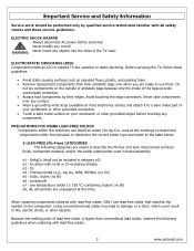
.... Disassembly Procedure Note: Before disassembly of antistatic bags because only the inside an LCD or plasma TV are sensitive to a bare metal part of your workbench or other grounded connection.... • Touch a bare metal surface on the outside of any components. 20 www.polaroid.com Never ...8226; Use a magnetized screwdriver for power within all system boards to discharge before touching any part the TV, make sure the power is OFF, and the power cord is large enough to hold components...
.... Disassembly Procedure Note: Before disassembly of antistatic bags because only the inside an LCD or plasma TV are sensitive to a bare metal part of your workbench or other grounded connection.... • Touch a bare metal surface on the outside of any components. 20 www.polaroid.com Never ...8226; Use a magnetized screwdriver for power within all system boards to discharge before touching any part the TV, make sure the power is OFF, and the power cord is large enough to hold components...
Service Manual
Page 21
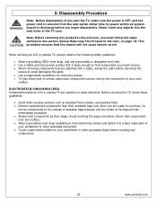
...polaroid.com Stand Removal (1) Lay TV flat on workbench. slide toward bottom of any objects into the vent holes in the sequence indicated below (1 thru 6). (3) Remove stand. *NOTE: Pictured is removed from being scratched. Allow time for power within all system boards to protect the front bezel and LCD... disassembly. Never insert any part the TV, make sure the power is OFF, and the power cord is a 26" model. 32" and 37" models will have different stand screw quantities and locations. Use protective cloth between work bench and TV front. Rear Cover Removal (4) Remove control...
...polaroid.com Stand Removal (1) Lay TV flat on workbench. slide toward bottom of any objects into the vent holes in the sequence indicated below (1 thru 6). (3) Remove stand. *NOTE: Pictured is removed from being scratched. Allow time for power within all system boards to protect the front bezel and LCD... disassembly. Never insert any part the TV, make sure the power is OFF, and the power cord is a 26" model. 32" and 37" models will have different stand screw quantities and locations. Use protective cloth between work bench and TV front. Rear Cover Removal (4) Remove control...
Service Manual
Page 23
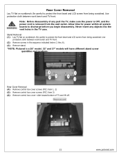
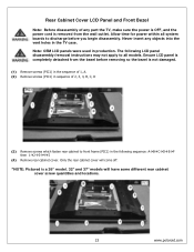
... then 1Æ2Æ3Æ4Æ5 (4) Remove rear cabinet cover. Note: OEM LCD panels were used in the TV case. Allow time for power within all system boards to all models. Ensure LCD panel is completely detached from the wall outlet. Rear Cabinet Cover LCD Panel and Front Bezel Note: Before disassembly of 2, 3, 4, B, C, ...) in sequence of any objects into the vent holes in production. Only the rear cabinet cover will come off. *NOTE: Pictured is a 26" model. 32" and 37" models will have some different rear cabinet cover screw quantities and locations. 23 www.polaroid.com
... then 1Æ2Æ3Æ4Æ5 (4) Remove rear cabinet cover. Note: OEM LCD panels were used in the TV case. Allow time for power within all system boards to all models. Ensure LCD panel is completely detached from the wall outlet. Rear Cabinet Cover LCD Panel and Front Bezel Note: Before disassembly of 2, 3, 4, B, C, ...) in sequence of any objects into the vent holes in production. Only the rear cabinet cover will come off. *NOTE: Pictured is a 26" model. 32" and 37" models will have some different rear cabinet cover screw quantities and locations. 23 www.polaroid.com
Service Manual
Page 29
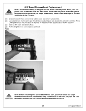
... Replacement Note: Before disassembly of the A/V assembly. (3) Slide out A/V board and replace (PIC2). (4) Push locking tabs in to secure replaced A/V board. Do the same for power within all system boards to discharge before you must follow the steps outlined in the TV case. (1) Disassemble control box cover and rear cabinet cover and remove ... this product to the User, on page 19. This procedure ensures that the chassis will not cause electric shock. 29 www.polaroid.com Never insert any part the TV, make sure the power is OFF, and the power cord is removed from the wall outlet.
... Replacement Note: Before disassembly of the A/V assembly. (3) Slide out A/V board and replace (PIC2). (4) Push locking tabs in to secure replaced A/V board. Do the same for power within all system boards to discharge before you must follow the steps outlined in the TV case. (1) Disassemble control box cover and rear cabinet cover and remove ... this product to the User, on page 19. This procedure ensures that the chassis will not cause electric shock. 29 www.polaroid.com Never insert any part the TV, make sure the power is OFF, and the power cord is removed from the wall outlet.
Service Manual
Page 30
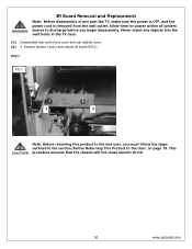
... outlined in the TV case. (1) Disassemble rear control box cover and rear cabinet cover. (2) 2. Allow time for power within all system boards to the User, on page 19. Remove screws 1 and 2 and replace IR board (PIC1). This procedure ensures that the chassis will not cause electric shock. 30 www.polaroid.com IR Board Removal and Replacement...
... outlined in the TV case. (1) Disassemble rear control box cover and rear cabinet cover. (2) 2. Allow time for power within all system boards to the User, on page 19. Remove screws 1 and 2 and replace IR board (PIC1). This procedure ensures that the chassis will not cause electric shock. 30 www.polaroid.com IR Board Removal and Replacement...

Service Manual
Page 31
... control button board and use glue to fasten to the end user, you begin disassembly. PIC1 Note: Before returning this product to front bezel. This procedure ensures that the chassis will not cause electric shock. 31 www.polaroid.com Never insert any part the TV, make sure the power is OFF,... and the power cord is attached with glue. Front/Side Control Buttons Removal and Replacement Note: Before disassembly of ...
... control button board and use glue to fasten to the end user, you begin disassembly. PIC1 Note: Before returning this product to front bezel. This procedure ensures that the chassis will not cause electric shock. 31 www.polaroid.com Never insert any part the TV, make sure the power is OFF,... and the power cord is attached with glue. Front/Side Control Buttons Removal and Replacement Note: Before disassembly of ...
Service Manual
Page 35
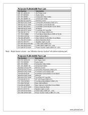
...GF271XAH Front/Side Control Button Bd. 154-500-GF321H Front/Side Control Button Cover Black 899-E00-GF271XAH IR Board 899-A00-GF271XAH Front/Side A/V Input Bd. 705-526-051C-1H 26" LCD Panel (CMO L01) 151-103-FL97WH Front Bezel Black/Black (CMO L01) 151-002-FL97GH Rear Cabinet...) 631-030-GF321XAH LVDS Cable (CMO L01 , L03) 631-N28-GF321XAH Power Inverter Cable (CMO L01, L03) 35 www.polaroid.com Model Version column - Polaroid FLM-2632M Part List Part Number Description 600-181-3200-LIH AC Power Cord 621-181-60002H Audio Cable 621-181-2000H Composite Video Cable 621-181...
...GF271XAH Front/Side Control Button Bd. 154-500-GF321H Front/Side Control Button Cover Black 899-E00-GF271XAH IR Board 899-A00-GF271XAH Front/Side A/V Input Bd. 705-526-051C-1H 26" LCD Panel (CMO L01) 151-103-FL97WH Front Bezel Black/Black (CMO L01) 151-002-FL97GH Rear Cabinet...) 631-030-GF321XAH LVDS Cable (CMO L01 , L03) 631-N28-GF321XAH Power Inverter Cable (CMO L01, L03) 35 www.polaroid.com Model Version column - Polaroid FLM-2632M Part List Part Number Description 600-181-3200-LIH AC Power Cord 621-181-60002H Audio Cable 621-181-2000H Composite Video Cable 621-181...
Service Manual
Page 38
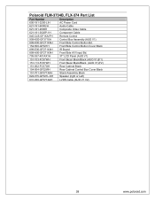
Polaroid FLM-3734B, FLX-374 Part List Part Number Description 600-181-3200-LIH AC Power Cord 621-181-60002H Audio Cable 621-181-2000H Composite Video Cable 621-181-3020P-1H Component Cable 845-C45-...Front/Side Control Button Bd. 154-500-GF321H Front/Side Control Button Cover Black 899-E00-GF271XAH IR Board 899-A00-GF271XAH Front/Side A/V Input Bd. 705-537-401AX1H 37" LCD Panel (AUO V1) 151-103-FC57WH Front Bezel Black/Black (AUO V1)(F1) 151-113-FC57WH ... Assembly Black 824-015-GF321L-KH Speaker (right or Left) 631-030-GF371XAH LVDS Cable (AUO V1 V2) 38 www.polaroid.com
Polaroid FLM-3734B, FLX-374 Part List Part Number Description 600-181-3200-LIH AC Power Cord 621-181-60002H Audio Cable 621-181-2000H Composite Video Cable 621-181-3020P-1H Component Cable 845-C45-...Front/Side Control Button Bd. 154-500-GF321H Front/Side Control Button Cover Black 899-E00-GF271XAH IR Board 899-A00-GF271XAH Front/Side A/V Input Bd. 705-537-401AX1H 37" LCD Panel (AUO V1) 151-103-FC57WH Front Bezel Black/Black (AUO V1)(F1) 151-113-FC57WH ... Assembly Black 824-015-GF321L-KH Speaker (right or Left) 631-030-GF371XAH LVDS Cable (AUO V1 V2) 38 www.polaroid.com

Service Manual
Page 50
...UD A Date: Friday , September 09, 2005 Sheet 1 of 1 www.polaroid.com 200PHD Series 2X8 (16pin) CON1 VCCSB 15 SW6-VOL-UP 13 ...3 LTDC_DATA 1 16 SW7-VOL-DOWN 14 SW5-CH-DOWN 12 SW3-MENU 10 SW1-POWER 8 LED_O 6 LTDC_ADDR 4 LTDC_CLK 2 200PHD-16LT CTRL. Key 200PHD Series 2X7 (14pin)... 5 6 3 4 FRONT_S_CHROMA 1 2 PHONE_A_L_O PHONE_A_R_O FRONT_A_R_IN FRONT_S_LUMA 200PHD-14LT AUX AV 5 0 D-SUB 37 PIN Board 200PHD Series 2X4 (8pin) CON3 VBLON ADJ_INV 7 8 5 6 3 4 1 2 200PHD-8LT INVERTER CTRL. ... 12 30 11 29 10 28 9 27 8 26 7 25 6 24 5 23 4 22 3 21 2 ...
...UD A Date: Friday , September 09, 2005 Sheet 1 of 1 www.polaroid.com 200PHD Series 2X8 (16pin) CON1 VCCSB 15 SW6-VOL-UP 13 ...3 LTDC_DATA 1 16 SW7-VOL-DOWN 14 SW5-CH-DOWN 12 SW3-MENU 10 SW1-POWER 8 LED_O 6 LTDC_ADDR 4 LTDC_CLK 2 200PHD-16LT CTRL. Key 200PHD Series 2X7 (14pin)... 5 6 3 4 FRONT_S_CHROMA 1 2 PHONE_A_L_O PHONE_A_R_O FRONT_A_R_IN FRONT_S_LUMA 200PHD-14LT AUX AV 5 0 D-SUB 37 PIN Board 200PHD Series 2X4 (8pin) CON3 VBLON ADJ_INV 7 8 5 6 3 4 1 2 200PHD-8LT INVERTER CTRL. ... 12 30 11 29 10 28 9 27 8 26 7 25 6 24 5 23 4 22 3 21 2 ...


