
Service Manual
Page 2
.... use a damp cloth for ventilation, to ensure reliable operation of the product and to protect it from the type of power source indicated on the marketing label. When the power cord or plug is provided. (8) This product should never be placed in a built-in the cabinet and the back or... bottom are provided for cleaning. (5) Do not use liquid cleaners or aerosol cleaners; The product may result in the user's manual for service. . 2 www.polaroid.com Do ...
.... use a damp cloth for ventilation, to ensure reliable operation of the product and to protect it from the type of power source indicated on the marketing label. When the power cord or plug is provided. (8) This product should never be placed in a built-in the cabinet and the back or... bottom are provided for cleaning. (5) Do not use liquid cleaners or aerosol cleaners; The product may result in the user's manual for service. . 2 www.polaroid.com Do ...
Service Manual
Page 3
...with lead-free solder, ONLY use them. Before servicing the TV, follow these service guidelines: ELECTRIC SHOCK HAZARD Always disconnect AC power before touching any surface. • Wear a grounding wrist strap... of your workbench or other hazards. Sn alloys with lead-free solder: 3 www.polaroid.com Never slide components over any components. PRECAUTIONS FOR USING LEAD-FREE SOLDER Components within...the symbol on the outside of antistatic bags because only the inside an LCD or plasma TV are sensitive to describe the Pb-free 2nd level interconnect terminal finish, ...
...with lead-free solder, ONLY use them. Before servicing the TV, follow these service guidelines: ELECTRIC SHOCK HAZARD Always disconnect AC power before touching any surface. • Wear a grounding wrist strap... of your workbench or other hazards. Sn alloys with lead-free solder: 3 www.polaroid.com Never slide components over any components. PRECAUTIONS FOR USING LEAD-FREE SOLDER Components within...the symbol on the outside of antistatic bags because only the inside an LCD or plasma TV are sensitive to describe the Pb-free 2nd level interconnect terminal finish, ...

Service Manual
Page 4
... bit may result in fire, electric shock, or other hazards. 4 www.polaroid.com Replacing individual parts with steel wool or fine sandpaper. (0) NOTICE ABOUT REPLACEMENT PARTS Many electrical and mechanical parts within LCD or plasma televisions are chosen for an extended period may damage the components.... (3) Because lead-free solder contains a higher concentration of tin, the tip of solder. Do not leave the bit powered on for higher voltage or wattage...
... bit may result in fire, electric shock, or other hazards. 4 www.polaroid.com Replacing individual parts with steel wool or fine sandpaper. (0) NOTICE ABOUT REPLACEMENT PARTS Many electrical and mechanical parts within LCD or plasma televisions are chosen for an extended period may damage the components.... (3) Because lead-free solder contains a higher concentration of tin, the tip of solder. Do not leave the bit powered on for higher voltage or wattage...

Service Manual
Page 11
Power on the TV simultaneously and release. 3. Factory Mode Procedure 1. Press volume up and channel up buttons on TV. 2. Power off TV with remote or power button to exit. 11 www.polaroid.com
Power on the TV simultaneously and release. 3. Factory Mode Procedure 1. Press volume up and channel up buttons on TV. 2. Power off TV with remote or power button to exit. 11 www.polaroid.com
Service Manual
Page 14
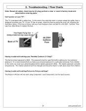
... fuse is blown, visit your own personal password. The factory preset password is equipped with a safety fuse. In the event you keep your TV has no power, check the fuse by AC plug, perform a clear or reset in a safe place and away from children. If the fuse is designed... below. 2. This password must be kept in -Picture will not work using Component 1 and Component 2 as the input sources. 14 www.polaroid.com The Picture-in a safe place away from children. This TV is 0000. The master password can't be changed and should be used first before ordering parts.
... fuse is blown, visit your own personal password. The factory preset password is equipped with a safety fuse. In the event you keep your TV has no power, check the fuse by AC plug, perform a clear or reset in a safe place and away from children. If the fuse is designed... below. 2. This password must be kept in -Picture will not work using Component 1 and Component 2 as the input sources. 14 www.polaroid.com The Picture-in a safe place away from children. This TV is 0000. The master password can't be changed and should be used first before ordering parts.
Service Manual
Page 20
...power within all system boards to discharge before touching any surface. • Wear a grounding wrist strap (available at most electronics stores) and attach it to a bare metal part of any objects into the vent holes in the TV case. Never slide components over any components. 20 www.polaroid...causing surfaces such as carpeted floors, plastic, and packing foam. • Remove replacement components from the wall outlet. When servicing an LCD or plasma TV, always observe the following safety guidelines: • Wear a grounding (ESD) wrist strap, and use them. Do not lay components ...
...power within all system boards to discharge before touching any surface. • Wear a grounding wrist strap (available at most electronics stores) and attach it to a bare metal part of any objects into the vent holes in the TV case. Never slide components over any components. 20 www.polaroid...causing surfaces such as carpeted floors, plastic, and packing foam. • Remove replacement components from the wall outlet. When servicing an LCD or plasma TV, always observe the following safety guidelines: • Wear a grounding (ESD) wrist strap, and use them. Do not lay components ...
Service Manual
Page 21
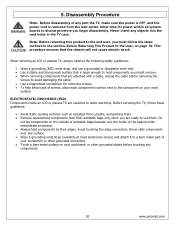
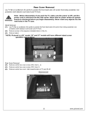
...TV front. (2) Remove screws in the TV case. Never insert any part the TV, make sure the power is OFF, and the power cord is a 26" model. 32" and 37" models will have different stand screw quantities and locations. Note: Before disassembly of TV and lift off. 21 www.polaroid.com Stand Removal (1) Lay TV... flat on workbench. Be careful to discharge before you begin disassembly. Use protective cloth between work bench and TV front. Allow time for power within all system boards to protect the front bezel and LCD ...
...TV front. (2) Remove screws in the TV case. Never insert any part the TV, make sure the power is OFF, and the power cord is a 26" model. 32" and 37" models will have different stand screw quantities and locations. Note: Before disassembly of TV and lift off. 21 www.polaroid.com Stand Removal (1) Lay TV... flat on workbench. Be careful to discharge before you begin disassembly. Use protective cloth between work bench and TV front. Allow time for power within all system boards to protect the front bezel and LCD ...

Service Manual
Page 22
Disconnect LVDS cable connector from LCD panel (PIC2). (9) Disconnect the LCD Panel power cord from back hinges and tilt to the User, on page 19. Release control box from bottom side of control box (PIC3). (7) Lift up the ...control box from the A/V connector side (PIC1). There are cables underneath that the chassis will not cause electric shock. 22 www.polaroid.com This...
Disconnect LVDS cable connector from LCD panel (PIC2). (9) Disconnect the LCD Panel power cord from back hinges and tilt to the User, on page 19. Release control box from bottom side of control box (PIC3). (7) Lift up the ...control box from the A/V connector side (PIC1). There are cables underneath that the chassis will not cause electric shock. 22 www.polaroid.com This...
Service Manual
Page 23
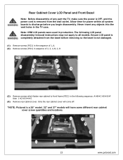
... have some different rear cabinet cover screw quantities and locations. 23 www.polaroid.com Never insert any part the TV, make sure the power is OFF, and the power cord is removed from the bezel before you begin disassembly. Ensure LCD panel is a 26" model. 32" and 37" models will come off. *NOTE: Pictured is completely...
... have some different rear cabinet cover screw quantities and locations. 23 www.polaroid.com Never insert any part the TV, make sure the power is OFF, and the power cord is removed from the bezel before you begin disassembly. Ensure LCD panel is a 26" model. 32" and 37" models will come off. *NOTE: Pictured is completely...
Service Manual
Page 29
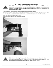
This procedure ensures that the chassis will not cause electric shock. 29 www.polaroid.com Do the same for power within all system boards to discharge before you must follow the steps outlined in the section, Before Returning This Product to secure replaced A/V board. PIC1 ...PIC2 Note: Before returning this product to the end user, you begin disassembly. Never insert any part the TV, make sure the power is OFF, and the power cord is removed from the wall outlet. Locking tabl should only pivot about 45 degrees. Allow time for the opposite side of...
This procedure ensures that the chassis will not cause electric shock. 29 www.polaroid.com Do the same for power within all system boards to discharge before you must follow the steps outlined in the section, Before Returning This Product to secure replaced A/V board. PIC1 ...PIC2 Note: Before returning this product to the end user, you begin disassembly. Never insert any part the TV, make sure the power is OFF, and the power cord is removed from the wall outlet. Locking tabl should only pivot about 45 degrees. Allow time for the opposite side of...
Service Manual
Page 30
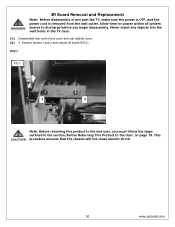
Remove screws 1 and 2 and replace IR board (PIC1). This procedure ensures that the chassis will not cause electric shock. 30 www.polaroid.com PIC1 PIC1 1 2 Note: Before returning this product to the User, on page 19. IR Board Removal and Replacement Note: Before disassembly of... holes in the section, Before Returning This Product to the end user, you begin disassembly. Allow time for power within all system boards to discharge before you must follow the steps outlined in the TV case. (1) Disassemble rear control box cover and rear cabinet cover. (2) 2. Never insert any part the...
Remove screws 1 and 2 and replace IR board (PIC1). This procedure ensures that the chassis will not cause electric shock. 30 www.polaroid.com PIC1 PIC1 1 2 Note: Before returning this product to the User, on page 19. IR Board Removal and Replacement Note: Before disassembly of... holes in the section, Before Returning This Product to the end user, you begin disassembly. Allow time for power within all system boards to discharge before you must follow the steps outlined in the TV case. (1) Disassemble rear control box cover and rear cabinet cover. (2) 2. Never insert any part the...

Service Manual
Page 31
...). (3) Replace control button board and use glue to fasten to discharge before you must follow the steps outlined in the TV case. (1) Disassemble control box cover and rear cabinet cover. (2) The control button board is removed from the wall outlet...product to the User, on page 19. Never insert any part the TV, make sure the power is OFF, and the power cord is attached with glue. Allow time for power within all system boards to front bezel. Front/Side Control Buttons Removal and... disassembly. This procedure ensures that the chassis will not cause electric shock. 31 www.polaroid.com
...). (3) Replace control button board and use glue to fasten to discharge before you must follow the steps outlined in the TV case. (1) Disassemble control box cover and rear cabinet cover. (2) The control button board is removed from the wall outlet...product to the User, on page 19. Never insert any part the TV, make sure the power is OFF, and the power cord is attached with glue. Allow time for power within all system boards to front bezel. Front/Side Control Buttons Removal and... disassembly. This procedure ensures that the chassis will not cause electric shock. 31 www.polaroid.com
Service Manual
Page 35
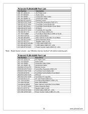
...500-GF321H Front/Side Control Button Cover Black 899-E00-GF271XAH IR Board 899-A00-GF271XAH Front/Side A/V Input Bd. 705-526-051C-1H 26" LCD Panel (CMO L01) 151-103-FL97WH Front Bezel Black/Black (CMO L01) 151-002-FL97GH Rear Cabinet Black 154-004-GF32WH Rear Cabinet ...LVDS Cable (CMO L01 , L03) 631-N28-GF321XAH Power Inverter Cable (CMO L01, L03) 35 www.polaroid.com Model Version column - see "Attention Service Centers" info before ordering part. Polaroid FLM-2632M Part List Part Number Description 600-181-3200-LIH AC Power Cord 621-181-60002H Audio Cable 621-181-2000H ...
...500-GF321H Front/Side Control Button Cover Black 899-E00-GF271XAH IR Board 899-A00-GF271XAH Front/Side A/V Input Bd. 705-526-051C-1H 26" LCD Panel (CMO L01) 151-103-FL97WH Front Bezel Black/Black (CMO L01) 151-002-FL97GH Rear Cabinet Black 154-004-GF32WH Rear Cabinet ...LVDS Cable (CMO L01 , L03) 631-N28-GF321XAH Power Inverter Cable (CMO L01, L03) 35 www.polaroid.com Model Version column - see "Attention Service Centers" info before ordering part. Polaroid FLM-2632M Part List Part Number Description 600-181-3200-LIH AC Power Cord 621-181-60002H Audio Cable 621-181-2000H ...
Service Manual
Page 38
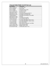
Polaroid FLM-3734B, FLX-374 Part List Part Number Description 600-181-3200-LIH AC Power Cord 621-181-60002H Audio Cable 621-181-2000H Composite Video Cable 621-181-3020P-1H Component Cable 845-C45-...-GF321H Front/Side Control Button Cover Black 899-E00-GF271XAH IR Board 899-A00-GF271XAH Front/Side A/V Input Bd. 705-537-401AX1H 37" LCD Panel (AUO V1) 151-103-FC57WH Front Bezel Black/Black (AUO V1)(F1) 151-113-FC57WH Front Bezel Black/Black (AUO V1)(F2... Assembly Black 824-015-GF321L-KH Speaker (right or Left) 631-030-GF371XAH LVDS Cable (AUO V1 V2) 38 www.polaroid.com
Polaroid FLM-3734B, FLX-374 Part List Part Number Description 600-181-3200-LIH AC Power Cord 621-181-60002H Audio Cable 621-181-2000H Composite Video Cable 621-181-3020P-1H Component Cable 845-C45-...-GF321H Front/Side Control Button Cover Black 899-E00-GF271XAH IR Board 899-A00-GF271XAH Front/Side A/V Input Bd. 705-537-401AX1H 37" LCD Panel (AUO V1) 151-103-FC57WH Front Bezel Black/Black (AUO V1)(F1) 151-113-FC57WH Front Bezel Black/Black (AUO V1)(F2... Assembly Black 824-015-GF321L-KH Speaker (right or Left) 631-030-GF371XAH LVDS Cable (AUO V1 V2) 38 www.polaroid.com

Service Manual
Page 43
... DDC 6. Clock + 11. TMDS Data 010. Green Video 3. Red Ground 7. SDA For DDC1/2B 13. CEC/GND 18. +5V Power 19. Schematics HMDI connector is described as below: 1: Ground 2: Ground 3: Y 4: C 43 www.polaroid.com Clock 13. Vdd from PC 10. 8. TMDS Data 2 shield 3. TMDS Data 1+ 5. TMDS Data 0 shield 9. CEC 14. NC 15...
... DDC 6. Clock + 11. TMDS Data 010. Green Video 3. Red Ground 7. SDA For DDC1/2B 13. CEC/GND 18. +5V Power 19. Schematics HMDI connector is described as below: 1: Ground 2: Ground 3: Y 4: C 43 www.polaroid.com Clock 13. Vdd from PC 10. 8. TMDS Data 2 shield 3. TMDS Data 1+ 5. TMDS Data 0 shield 9. CEC 14. NC 15...

Service Manual
Page 46
Red 2. SCL 46 www.polaroid.com Ground 5. Green Gro und 12. Power Source Sound Output AC100 - 240 V, 60/50 Hz 10W X2, 8 Ohm. Green 3. Red Ground 11. Ground 7. Horizontal Sync. 9. Blue Ground 13. Not Connected 14. Sync. Ground 15. SDA 8. Signal Connector Pin Assignment Pin Assignment 1. Vertical Sync. 10. Blue 4. Self Test Pin Assignment Pin Assignment 6.
Red 2. SCL 46 www.polaroid.com Ground 5. Green Gro und 12. Power Source Sound Output AC100 - 240 V, 60/50 Hz 10W X2, 8 Ohm. Green 3. Red Ground 11. Ground 7. Horizontal Sync. 9. Blue Ground 13. Not Connected 14. Sync. Ground 15. SDA 8. Signal Connector Pin Assignment Pin Assignment 1. Vertical Sync. 10. Blue 4. Self Test Pin Assignment Pin Assignment 6.

Service Manual
Page 48
... Fax: 886-2-2232-4613 Title KEYPAD PCB Size Document Number Rev A GF371-XU A Date: Friday , September 30, 2005 Sheet 1 of 1 48 www.polaroid.com Front/Side Control Buttons SW1 POWER-ON SW2 SOURCE SW3 MENU SW4 CH-UP SW5 CH-DOWN SW6 VOL-UP SW7 VOL-DOWN VCC R1 4.7K R2 4.7K... R3 4.7K R4 4.7K R5 4.7K R6 4.7K R7 4.7K C1 0.1uF J1 VCC POWER-ON 1 SOERCE 2 MENU 3 CH-UP 4 CH-DOWN 5 VOL-UP 6 VOL-DOWN 7 GND 8 9 CON9 Hous 9P-1.0 ZD1 5.6V ZD2 5.6V ZD3 5.6V ZD4 5.6V ZD5 5.6V...
... Fax: 886-2-2232-4613 Title KEYPAD PCB Size Document Number Rev A GF371-XU A Date: Friday , September 30, 2005 Sheet 1 of 1 48 www.polaroid.com Front/Side Control Buttons SW1 POWER-ON SW2 SOURCE SW3 MENU SW4 CH-UP SW5 CH-DOWN SW6 VOL-UP SW7 VOL-DOWN VCC R1 4.7K R2 4.7K... R3 4.7K R4 4.7K R5 4.7K R6 4.7K R7 4.7K C1 0.1uF J1 VCC POWER-ON 1 SOERCE 2 MENU 3 CH-UP 4 CH-DOWN 5 VOL-UP 6 VOL-DOWN 7 GND 8 9 CON9 Hous 9P-1.0 ZD1 5.6V ZD2 5.6V ZD3 5.6V ZD4 5.6V ZD5 5.6V...

Service Manual
Page 50
... 35 16 34 15 33 14 32 13 31 12 30 11 29 10 28 9 27 8 26 7 25 6 24 5 23 4 22 3 21 2 20 1 D-SUB 37P FEMALE SPK_R_OUT+ SPK_R_OUTPHONE_A_L_O PHONE_A_R_O ...FRONT_A_R_IN FRONT_S_LUMA SW7-VOL-DOWN SW5-CH-DOWN SW3-MENU SW1-POWER LED_O LTDC_ADDR LTDC_CLK VBLON AD J _I N V Proview Electronics (Taiwan) Co., LTD. 6F, NO.1, Pau-Sheng Rd.,...Size Document Number Rev C us t om JK379-UD A Date: Friday , September 09, 2005 Sheet 1 of 1 www.polaroid.com 200PHD Series 2X8 (16pin) CON1 VCCSB 15 SW6-VOL-UP 13 SW4-CH-UP 11 SW2-SOURCE 9 LED_G 7 ...
... 35 16 34 15 33 14 32 13 31 12 30 11 29 10 28 9 27 8 26 7 25 6 24 5 23 4 22 3 21 2 20 1 D-SUB 37P FEMALE SPK_R_OUT+ SPK_R_OUTPHONE_A_L_O PHONE_A_R_O ...FRONT_A_R_IN FRONT_S_LUMA SW7-VOL-DOWN SW5-CH-DOWN SW3-MENU SW1-POWER LED_O LTDC_ADDR LTDC_CLK VBLON AD J _I N V Proview Electronics (Taiwan) Co., LTD. 6F, NO.1, Pau-Sheng Rd.,...Size Document Number Rev C us t om JK379-UD A Date: Friday , September 09, 2005 Sheet 1 of 1 www.polaroid.com 200PHD Series 2X8 (16pin) CON1 VCCSB 15 SW6-VOL-UP 13 SW4-CH-UP 11 SW2-SOURCE 9 LED_G 7 ...
User Guide
Page 3
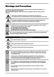
... electric shock. This symbol indicates actions that must not be observed in the installation, use, servicing and maintenance of this equipment from the type of power source indicated on the 3-prong plug is intended to alert the user to overturn. ▪ Do not disable the 3-wire grounding type plug. The equipment...
... electric shock. This symbol indicates actions that must not be observed in the installation, use, servicing and maintenance of this equipment from the type of power source indicated on the 3-prong plug is intended to alert the user to overturn. ▪ Do not disable the 3-wire grounding type plug. The equipment...

User Guide
Page 4
..., stands, tables, shelves etc. Clean only with care. Do not place any other hazards and may cause poor ventilation. ▪ Always remove the power cord from the outlet before cleaning the equipment. ▪ Never use or handle this equipment near water. ▪ Never expose the equipment to direct ...to children or adults and serious damage to fire or electric shock. ▪ Do not place the equipment on the AC power cord. ▪ Do not pull the AC power cord. Inserting any other similar places that is spilled into the ventilation holes of the equipment. ▪ Do not block...
..., stands, tables, shelves etc. Clean only with care. Do not place any other hazards and may cause poor ventilation. ▪ Always remove the power cord from the outlet before cleaning the equipment. ▪ Never use or handle this equipment near water. ▪ Never expose the equipment to direct ...to children or adults and serious damage to fire or electric shock. ▪ Do not place the equipment on the AC power cord. ▪ Do not pull the AC power cord. Inserting any other similar places that is spilled into the ventilation holes of the equipment. ▪ Do not block...


