Service Manual
Page 1
North America TLA-04011C, TLXB-4011, TLXB-4241 SERVICE MANUAL Bezel covers vary by model 20070613 2007 LCD Models -
North America TLA-04011C, TLXB-4011, TLXB-4241 SERVICE MANUAL Bezel covers vary by model 20070613 2007 LCD Models -
Service Manual
Page 3
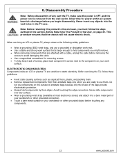
... components on your workbench or other grounded connection. • Touch a bare metal surface on the outside of antistatic bags because only the inside an LCD or plasma TV are sensitive to a bare metal part of the bags provide electrostatic protection. • Always hold components by qualified service technicians familiar with components rated... Service and Safety Information Service work should be performed only by their edges. ELECTROSTATIC DISCHARGE (ESD) Components inside of your workbench or other hazards. 3 www.polaroid.com
... components on your workbench or other grounded connection. • Touch a bare metal surface on the outside of antistatic bags because only the inside an LCD or plasma TV are sensitive to a bare metal part of the bags provide electrostatic protection. • Always hold components by qualified service technicians familiar with components rated... Service and Safety Information Service work should be performed only by their edges. ELECTROSTATIC DISCHARGE (ESD) Components inside of your workbench or other hazards. 3 www.polaroid.com
Service Manual
Page 5
......22 Stand and Control Box Removal 23 Rear Cabinet Cover, LCD Panel and Front Bezel 25 IR Board Removal and Replacement 32 Front/Side Control Buttons Removal and Replacement 33 7. Troubleshooting / Flow Charts ...16 Factory Mode Procedure...16 4. Schematics ...38 11. Polaroid Display Cell Defect Specification 20 5. Specifications...6 2. Before Returning This Product...
......22 Stand and Control Box Removal 23 Rear Cabinet Cover, LCD Panel and Front Bezel 25 IR Board Removal and Replacement 32 Front/Side Control Buttons Removal and Replacement 33 7. Troubleshooting / Flow Charts ...16 Factory Mode Procedure...16 4. Schematics ...38 11. Polaroid Display Cell Defect Specification 20 5. Specifications...6 2. Before Returning This Product...

Service Manual
Page 20
These defective cells can be controlled. 4. Polaroid Display Cell Defect Specification In some cases, a panel may have defective cells that cannot be categorized into two types; (1) Non-lighting or dark cell defect: ...defect in which the cell is always off (2) Non-extinguishing or bright cell defect: defect in which the cell is always on The Polaroid Display Cell Defect Specifications below define the allowed limits for display cell defects and are used as the criteria in determining whether an...
These defective cells can be controlled. 4. Polaroid Display Cell Defect Specification In some cases, a panel may have defective cells that cannot be categorized into two types; (1) Non-lighting or dark cell defect: ...defect in which the cell is always off (2) Non-extinguishing or bright cell defect: defect in which the cell is always on The Polaroid Display Cell Defect Specifications below define the allowed limits for display cell defects and are used as the criteria in determining whether an...
Service Manual
Page 22
...or other grounded connection. • Touch a bare metal surface on the outside of antistatic bags because only the inside an LCD or plasma TV are ready to the component on page 21. Do not lay components on your workbench or other grounded object before removing the... you might remove. • When removing components that the chassis will not cause electric shock. Never slide components over any components. 22 www.polaroid.com ELECTROSTATIC DISCHARGE (ESD) Components inside of screws, place each component's screws next to use a grounded or dissipative work mat. • ...
...or other grounded connection. • Touch a bare metal surface on the outside of antistatic bags because only the inside an LCD or plasma TV are ready to the component on page 21. Do not lay components on your workbench or other grounded object before removing the... you might remove. • When removing components that the chassis will not cause electric shock. Never slide components over any components. 22 www.polaroid.com ELECTROSTATIC DISCHARGE (ESD) Components inside of screws, place each component's screws next to use a grounded or dissipative work mat. • ...
Service Manual
Page 23
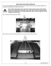
... of any objects into the vent holes in the TV case. (1) Remove 4 screws (A) from being scratched. A 23 www.polaroid.com Allow time for power within all system boards to protect the front bezel and LCD screen from the TV Stand. Stand and Control Box Removal Lay TV flat on workbench. A (2) Remove 3 screws (A) from the Control...
... of any objects into the vent holes in the TV case. (1) Remove 4 screws (A) from being scratched. A 23 www.polaroid.com Allow time for power within all system boards to protect the front bezel and LCD screen from the TV Stand. Stand and Control Box Removal Lay TV flat on workbench. A (2) Remove 3 screws (A) from the Control...

Service Manual
Page 25
... Note: Before disassembly of any objects into the vent holes in production. A 25 www.polaroid.com Note: OEM LCD panels were used in the TV case. Ensure LCD panel is not damaged. (1) Remove 6 screws (A) from the wall outlet. The following LCD panel disassembly/removal instructions may not apply to discharge before removing so the bezel...
... Note: Before disassembly of any objects into the vent holes in production. A 25 www.polaroid.com Note: OEM LCD panels were used in the TV case. Ensure LCD panel is not damaged. (1) Remove 6 screws (A) from the wall outlet. The following LCD panel disassembly/removal instructions may not apply to discharge before removing so the bezel...

Service Manual
Page 31
This procedure ensures that the chassis will not cause electric shock. 31 www.polaroid.com A NOTE: To avoid damage, TWO PEOPLE ARE REQUIRED to the User, on page 21. Note: Before returning this product to the end user, you must follow the steps outlined in the section, Before Returning This Product to lift the LCD Panel from left speaker. Repeat procedure for right speaker. (14) Remove clip (A) from the TV.
This procedure ensures that the chassis will not cause electric shock. 31 www.polaroid.com A NOTE: To avoid damage, TWO PEOPLE ARE REQUIRED to the User, on page 21. Note: Before returning this product to the end user, you must follow the steps outlined in the section, Before Returning This Product to lift the LCD Panel from left speaker. Repeat procedure for right speaker. (14) Remove clip (A) from the TV.
Service Manual
Page 34
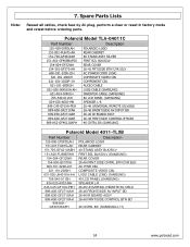
... (SAMSUNG) 40 LCD PANEL (SAMSUNG) SPEAKER L-R 845-C45-GF1XA-PEH 899-A00-GF271XAH 26-46 UNIVERSAL REMOTE SILV/BLK 26-46 FRONT/SIDE AV INPUT BD 899-E00-GF271XAH 899-K00-GF271XAH 909-KS2-GF4012XAPH 26-46 IR BOARD ASSY 26-46 FRNT/SIDE CONTROL BTN BD 40 CNTRL BX (SAMSUNG) Polaroid Model 4011-TLXB Part...-JK401XA-AH 705-540-011SH 824-020-A002-MH 845-C45-GF1XA-PEH 899-A00-GF271XAH 899-E00-GF271XAH 899-K00-GF271XAH 909-KS1GF4012XAPH POLAROID LOGO REAR CABINET 40 STAND ASSY BLK/SILV FRNT BZL BLK/SILV (SAMSUNG) REAR COVER 26-46 FRNT SIDE CNTRL BTN CVR BLK AC PWR CBL COMPOSITE...
... (SAMSUNG) 40 LCD PANEL (SAMSUNG) SPEAKER L-R 845-C45-GF1XA-PEH 899-A00-GF271XAH 26-46 UNIVERSAL REMOTE SILV/BLK 26-46 FRONT/SIDE AV INPUT BD 899-E00-GF271XAH 899-K00-GF271XAH 909-KS2-GF4012XAPH 26-46 IR BOARD ASSY 26-46 FRNT/SIDE CONTROL BTN BD 40 CNTRL BX (SAMSUNG) Polaroid Model 4011-TLXB Part...-JK401XA-AH 705-540-011SH 824-020-A002-MH 845-C45-GF1XA-PEH 899-A00-GF271XAH 899-E00-GF271XAH 899-K00-GF271XAH 909-KS1GF4012XAPH POLAROID LOGO REAR CABINET 40 STAND ASSY BLK/SILV FRNT BZL BLK/SILV (SAMSUNG) REAR COVER 26-46 FRNT SIDE CNTRL BTN CVR BLK AC PWR CBL COMPOSITE...
User Guide
Page 1
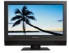
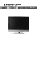
40" HD Widescreen LCD Television TLA-04011C and 4011-TLXB
40" HD Widescreen LCD Television TLA-04011C and 4011-TLXB
User Guide
Page 7
... CONTENTS Federal Communications Commission Statement 1 Warnings and Precautions Important Safety Instructions 2 Antenna Safety Instructions 4 Chapter 1 Introducing the LCD TV Key Features ...6 Package Contents ...7 Setting Your LCD TV...8 Your LCD TV...11 Your Remote Control 13 Chapter 2 Installing the LCD TV Connecting a TV Cable or an Antenna 15 Connecting a VCR ...20 Connecting a Video Camera or Game Console 21 Connecting a DVD...
... CONTENTS Federal Communications Commission Statement 1 Warnings and Precautions Important Safety Instructions 2 Antenna Safety Instructions 4 Chapter 1 Introducing the LCD TV Key Features ...6 Package Contents ...7 Setting Your LCD TV...8 Your LCD TV...11 Your Remote Control 13 Chapter 2 Installing the LCD TV Connecting a TV Cable or an Antenna 15 Connecting a VCR ...20 Connecting a Video Camera or Game Console 21 Connecting a DVD...

User Guide
Page 8
.../Audio input terminals ▪ 1 set of Audio(L/R) output terminals ▪ 2 SPDIF output terminals (Optical x 1 /Coaxial x 1) ▪ 1 Headphone terminal The built-in TV tuner to receive HD ATSC ▪ This function allows the reception of HD broadcasting without the addition of a set -top-box (1080i, 720p) connections. 3D... frame matching to provide a more natural-looking, clearer image of combined video and audio in a single cable. Chapter 1 Introducing the LCD TV Chapter 1 Introducing the LCD TV Key Features Various Audio/Video terminals for DVD (1080i, 720p) and digital set top box.
.../Audio input terminals ▪ 1 set of Audio(L/R) output terminals ▪ 2 SPDIF output terminals (Optical x 1 /Coaxial x 1) ▪ 1 Headphone terminal The built-in TV tuner to receive HD ATSC ▪ This function allows the reception of HD broadcasting without the addition of a set -top-box (1080i, 720p) connections. 3D... frame matching to provide a more natural-looking, clearer image of combined video and audio in a single cable. Chapter 1 Introducing the LCD TV Chapter 1 Introducing the LCD TV Key Features Various Audio/Video terminals for DVD (1080i, 720p) and digital set top box.
User Guide
Page 9
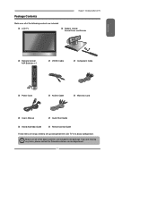
LCD TV Bottom Stand / Screw Driver and Screws ENGLISH Remote Control/ AAA Batteries x 2 SET UP TV CAB/ SAT DVD AUX SLEEP DVD MENU VOL CH PAGE MUTE ASPECT LAST GUIDE LIVE TV PIP MENU OK INFO CC EXIT DVR 1 2 3 ABC DEF 4 5 6 GHI JKL MNO 7 8 9 PQRS TUV WXYZ INPUT . 0 ENTER ...all you are included in its basic configuration. If you need to set up and operate the LCD TV in the package. Package Contents Chapter 1 Introducing the LCD TV Make sure all of the following contents are included. Make sure all of the above contents are missing any...
LCD TV Bottom Stand / Screw Driver and Screws ENGLISH Remote Control/ AAA Batteries x 2 SET UP TV CAB/ SAT DVD AUX SLEEP DVD MENU VOL CH PAGE MUTE ASPECT LAST GUIDE LIVE TV PIP MENU OK INFO CC EXIT DVR 1 2 3 ABC DEF 4 5 6 GHI JKL MNO 7 8 9 PQRS TUV WXYZ INPUT . 0 ENTER ...all you are included in its basic configuration. If you need to set up and operate the LCD TV in the package. Package Contents Chapter 1 Introducing the LCD TV Make sure all of the following contents are included. Make sure all of the above contents are missing any...

User Guide
Page 10
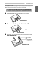
...box. Secure the stand to the LCD with the bottom foam packaging material still attached, and place onto a stable surface. Chapter 1 Introducing the LCD TV Setting Up Your LCD TV How to install the TV Stand Read all four screws. Attach the Stand the TV with the stand installation. b. ...a Stand Shipping box b Protective bag Table c. Remove protective bag from LCD unit, but DO NOT remove the ...
...box. Secure the stand to the LCD with the bottom foam packaging material still attached, and place onto a stable surface. Chapter 1 Introducing the LCD TV Setting Up Your LCD TV How to install the TV Stand Read all four screws. Attach the Stand the TV with the stand installation. b. ...a Stand Shipping box b Protective bag Table c. Remove protective bag from LCD unit, but DO NOT remove the ...
User Guide
Page 11
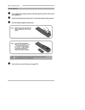
Contact a qualified technician for your TV model only. ENGLISH Chapter 1 Introducing the LCD TV How to remove the TV Stand If you prefer to mount your new Polaroid TV on a soft cloth. To prevent damaging the surface of the LCD TV, place the TV on a wall instead of attaching it to use the wall ...mounting kit specified for assistance when installing the wall mounting kit. Soft cloth Remove the screws of the TV and fasten ...
Contact a qualified technician for your TV model only. ENGLISH Chapter 1 Introducing the LCD TV How to remove the TV Stand If you prefer to mount your new Polaroid TV on a soft cloth. To prevent damaging the surface of the LCD TV, place the TV on a wall instead of attaching it to use the wall ...mounting kit specified for assistance when installing the wall mounting kit. Soft cloth Remove the screws of the TV and fasten ...
User Guide
Page 12
...the batteries with the (+) and ( - ) ends indicated in remote control. Connect other an external AV device (refer to the LCD TV's ANT. Chapter 1 Introducing the LCD TV How to setup the TV Use a supplied antenna cable to connect the VHF/UHF signal to page19-27). 10 Step1 Slide the back cover up to... match the (+) and ( - ) ends of the TV and connect the power cord to page15-17). Step2 Insert two AAA size ...
...the batteries with the (+) and ( - ) ends indicated in remote control. Connect other an external AV device (refer to the LCD TV's ANT. Chapter 1 Introducing the LCD TV How to setup the TV Use a supplied antenna cable to connect the VHF/UHF signal to page19-27). 10 Step1 Slide the back cover up to... match the (+) and ( - ) ends of the TV and connect the power cord to page15-17). Step2 Insert two AAA size ...
User Guide
Page 13
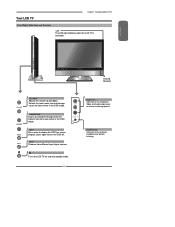
... to display the OSD (on screen display), press again to the composite Video and Audio output jacks on and into standby mode. 11 Turns the LCD TV on external video equipment. Selects the main-menu item and change values for private listening. Selects sub-menu item when in the OSD mode. CHANNEL...▲▼ Scans up and down through channels. HEADPHONE Connects to the external headphone for items when in the OSD mode. Your LCD TV Chapter 1 Introducing the LCD TV Front/Right Side View and Controls LED The LED light indicates when the...
... to display the OSD (on screen display), press again to the composite Video and Audio output jacks on and into standby mode. 11 Turns the LCD TV on external video equipment. Selects the main-menu item and change values for private listening. Selects sub-menu item when in the OSD mode. CHANNEL...▲▼ Scans up and down through channels. HEADPHONE Connects to the external headphone for items when in the OSD mode. Your LCD TV Chapter 1 Introducing the LCD TV Front/Right Side View and Controls LED The LED light indicates when the...
User Guide
Page 14
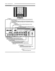
...AUDIO(L/R) output jacks. VGA IN Connects the PC, or other AV equipment with component(YPbPr) video and audio output jacks. Chapter 1 Introducing the LCD TV Rear View and Jacks VIDEO2 IN Connects to receive high/standard definition television. The AUDIO(L/R) of HDMI IN is for DVI connection. ...HDTV/TV Air/CABLE VHF/UHF IN TV CABLE/AIR Connects RF input from VHF/UHF antenna or cable to the composite VIDEO and AUDIO(L/R) output jacks on external ...
...AUDIO(L/R) output jacks. VGA IN Connects the PC, or other AV equipment with component(YPbPr) video and audio output jacks. Chapter 1 Introducing the LCD TV Rear View and Jacks VIDEO2 IN Connects to receive high/standard definition television. The AUDIO(L/R) of HDMI IN is for DVI connection. ...HDTV/TV Air/CABLE VHF/UHF IN TV CABLE/AIR Connects RF input from VHF/UHF antenna or cable to the composite VIDEO and AUDIO(L/R) output jacks on external ...
User Guide
Page 15
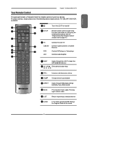
... Chapter 1 Introducing the LCD TV This package includes a Polaroid remote that enables control of the following device mode controls: TV, CBL/SAT, DVD/VCR, or AUDIO. 2 SET UP 1 3 TV CAB/ SAT DVD AUX SLEEP 4 DVD MENU 5 6 VOL CH PAGE 7 8 9 MUTE ASPECT LAST 10 LIVE TV GUIDE PIP MENU 11 ...90/120 mins Other device function keys 6 VOL+- Pressing again restores audio 10 LAST Returns to page 47) 3 TV CAB/SAT DVD AUX Controls this LCD TV Controls Cable Converter or Satellite Receiver Controls DVD player or Video player Controls Audio Amplifier 24 SLEEP 5 ►...
... Chapter 1 Introducing the LCD TV This package includes a Polaroid remote that enables control of the following device mode controls: TV, CBL/SAT, DVD/VCR, or AUDIO. 2 SET UP 1 3 TV CAB/ SAT DVD AUX SLEEP 4 DVD MENU 5 6 VOL CH PAGE 7 8 9 MUTE ASPECT LAST 10 LIVE TV GUIDE PIP MENU 11 ...90/120 mins Other device function keys 6 VOL+- Pressing again restores audio 10 LAST Returns to page 47) 3 TV CAB/SAT DVD AUX Controls this LCD TV Controls Cable Converter or Satellite Receiver Controls DVD player or Video player Controls Audio Amplifier 24 SLEEP 5 ►...
User Guide
Page 16
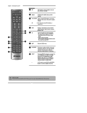
...source list, use ▲▼buttons to select the video equipment connected to the video inputs of your LCD TV: TV/VIDEO1/ VIDEO2/VIDEO3/VIDEO4/VIDEO5/ VIDEO6/VIDEO7/COMPUTER ▪ In TV mode, use with 0-9 and ENTER buttons to select a digital channels Effective range: The remote can ...ENTER Pressing a number selects a channel. Chapter 1 Introducing the LCD TV 12 PIP PIP function is not available. SET UP TV CAB/ SAT DVD AUX SLEEP DVD MENU 13 MENU Displays the OSD menu on the LCD TV MUTE ASPECT LAST LIVE TV 12 screen such as input source, channel, program title.
...source list, use ▲▼buttons to select the video equipment connected to the video inputs of your LCD TV: TV/VIDEO1/ VIDEO2/VIDEO3/VIDEO4/VIDEO5/ VIDEO6/VIDEO7/COMPUTER ▪ In TV mode, use with 0-9 and ENTER buttons to select a digital channels Effective range: The remote can ...ENTER Pressing a number selects a channel. Chapter 1 Introducing the LCD TV 12 PIP PIP function is not available. SET UP TV CAB/ SAT DVD AUX SLEEP DVD MENU 13 MENU Displays the OSD menu on the LCD TV MUTE ASPECT LAST LIVE TV 12 screen such as input source, channel, program title.


