Service Manual
Page 5
... 1. Block Diagram ...37 10. Go to polaroid.com to the User 21 6. Specifications...6 2. Before Returning This Product to obtain User Manual. 5 www.polaroid.com PCB Layout Diagrams...47 Model Specifications are located in User Manual. Disassembly Procedure...22 Stand and Control Box Removal 23 Rear Cabinet Cover, LCD Panel and Front Bezel 25 IR Board...
... 1. Block Diagram ...37 10. Go to polaroid.com to the User 21 6. Specifications...6 2. Before Returning This Product to obtain User Manual. 5 www.polaroid.com PCB Layout Diagrams...47 Model Specifications are located in User Manual. Disassembly Procedure...22 Stand and Control Box Removal 23 Rear Cabinet Cover, LCD Panel and Front Bezel 25 IR Board...
Service Manual
Page 23
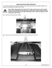
...into the vent holes in the TV case. (1) Remove 4 screws (A) from the wall outlet. A 23 www.polaroid.com Be careful to discharge before you begin disassembly. A (2) Remove 3 screws (A) from the Control Box Cover, and remove the Cover from being scratched. Never insert any part the TV, make sure the power is... OFF, and the power cord is removed from the TV Stand. Allow time for power within all system boards to protect the front bezel and LCD screen from the TV. Stand and Control Box Removal Lay TV flat on workbench. Use ...
...into the vent holes in the TV case. (1) Remove 4 screws (A) from the wall outlet. A 23 www.polaroid.com Be careful to discharge before you begin disassembly. A (2) Remove 3 screws (A) from the Control Box Cover, and remove the Cover from being scratched. Never insert any part the TV, make sure the power is... OFF, and the power cord is removed from the TV Stand. Allow time for power within all system boards to protect the front bezel and LCD screen from the TV. Stand and Control Box Removal Lay TV flat on workbench. Use ...

Service Manual
Page 24
...polaroid.com A Note: Before returning this product to the end user, you must follow the steps outlined in the section, Before Returning This Product to unhook it. (5) Remove the aluminum foil and bracket from the end of the Control Box. (3) Remove 6 screws (A) from the TV. Unplug the 2 cables (A) from the Control Box..., and remove the Box from the Control Box. A (4) Lift the Control Box upwards, and then towards the bottom of the TV to the User, on page ...
...polaroid.com A Note: Before returning this product to the end user, you must follow the steps outlined in the section, Before Returning This Product to unhook it. (5) Remove the aluminum foil and bracket from the end of the Control Box. (3) Remove 6 screws (A) from the TV. Unplug the 2 cables (A) from the Control Box..., and remove the Box from the Control Box. A (4) Lift the Control Box upwards, and then towards the bottom of the TV to the User, on page ...
Service Manual
Page 32
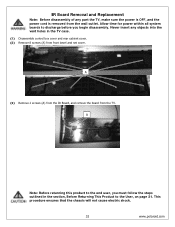
A Note: Before returning this product to the end user, you must follow the steps outlined in the TV case. (1) Disassemble control box cover and rear cabinet cover. (2) Remove 8 screws (A) from the TV. Never insert any part the TV, make sure the power is OFF, and the power cord is removed from the wall outlet. Allow time... the section, Before Returning This Product to discharge before you begin disassembly. This procedure ensures that the chassis will not cause electric shock. 32 www.polaroid.com
A Note: Before returning this product to the end user, you must follow the steps outlined in the TV case. (1) Disassemble control box cover and rear cabinet cover. (2) Remove 8 screws (A) from the TV. Never insert any part the TV, make sure the power is OFF, and the power cord is removed from the wall outlet. Allow time... the section, Before Returning This Product to discharge before you begin disassembly. This procedure ensures that the chassis will not cause electric shock. 32 www.polaroid.com
Service Manual
Page 33
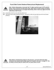
...that the chassis will not cause electric shock. 33 www.polaroid.com Front/Side Control Buttons Removal and Replacement Note: Before disassembly of any objects into the vent holes in the section, Before Returning This Product to soften the glue and remove the control button board (A). A Note: Before returning this product ...the User, on page 21. Allow time for power within all system boards to discharge before you must follow the steps outlined in the TV case. (1) Disassemble control box cover and rear cabinet cover. (2) The control button board is removed from the wall outlet.
...that the chassis will not cause electric shock. 33 www.polaroid.com Front/Side Control Buttons Removal and Replacement Note: Before disassembly of any objects into the vent holes in the section, Before Returning This Product to soften the glue and remove the control button board (A). A Note: Before returning this product ...the User, on page 21. Allow time for power within all system boards to discharge before you must follow the steps outlined in the TV case. (1) Disassemble control box cover and rear cabinet cover. (2) The control button board is removed from the wall outlet.
User Guide
Page 7
... Important Safety Instructions 2 Antenna Safety Instructions 4 Chapter 1 Introducing the LCD TV Key Features ...6 Package Contents ...7 Setting Your LCD TV...8 Your LCD TV...11 Your Remote Control 13 Chapter 2 Installing the LCD TV Connecting a TV Cable or an Antenna 15 Connecting a VCR ...20 Connecting a Video... Camera or Game Console 21 Connecting a DVD Player 22 Connecting a Digital TV Cable Box or Digital...
... Important Safety Instructions 2 Antenna Safety Instructions 4 Chapter 1 Introducing the LCD TV Key Features ...6 Package Contents ...7 Setting Your LCD TV...8 Your LCD TV...11 Your Remote Control 13 Chapter 2 Installing the LCD TV Connecting a TV Cable or an Antenna 15 Connecting a VCR ...20 Connecting a Video... Camera or Game Console 21 Connecting a DVD Player 22 Connecting a Digital TV Cable Box or Digital...


